Wiring harness design in CATIA V5 - 3D modeling Week 2 Challenge
3-D Modeling Week 2 Challenge
The relevant CAD data of the connectors are downloaded from the te.com website. These files are in the .step format and hence are opened in the CATIA software. As these files are part models of the connectors, they are saved as .CATPart files in the relevant folder. For an electrical component to be used for harness routing assembly, it has to be electrically defined. Since in it’s initial form, the component is in the form of mechanical part, it has to be converted into an electrical part. Before defining the part as electrical, it has to have certain features such as connector connection point, connector connection axis, bundle coaction point, cavity connection point etc. in case of connectors,
Creating Geometrical parameters:
For the downloaded CAD data of the connectors, the geometrical parameters such as the Connector Conection Point, Connector Connection Axis, Bundle Connection Point and Cavity Connection Point. It is to be noted that the cavity connection point is to be created only if the connector possesses clip mounting feature. So, the geometrical parameters are created in the Mechanical ‘Part Design’ workbench.
- Deutsch DT06 – 08SA:
This connector does not have Clip Mounting feature, hence there is no need to create Cavity Connection point.
Connector Connection Point
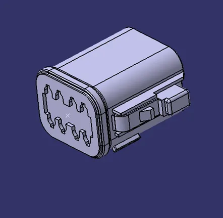
Connector Connection Axis
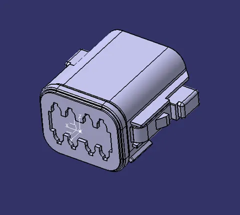
Bundle Connection Point
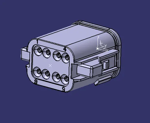
- Tyco 174357-2
This connector has clip mounting feature, thus the cavity connection point and the corresponding axis have to be created.
Connector Connection Point
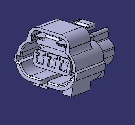
Connector Connection Axis
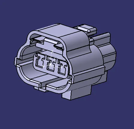
Bundle Connection Point
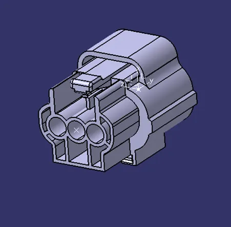
Cavity Connection Point
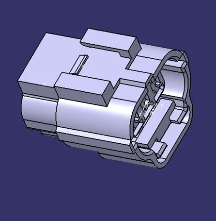
Cavity Connection Axis
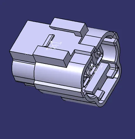
- Tyco 85229-1
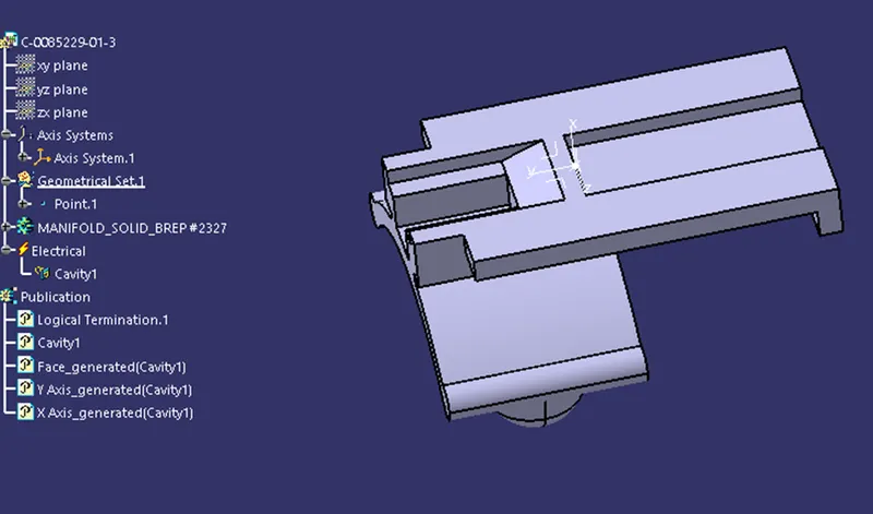
This part is a mounting clip that is usually attached to a connector body to mount the connector into a larger assembly so that the position of the connector is not altered. This clip only has a cavity connection point with a corresponding axis system.
Cavity Connection Point
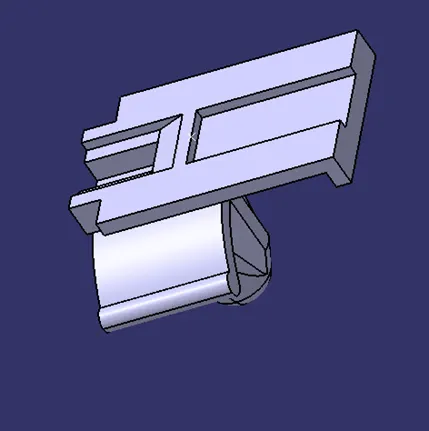
Cavity Connection Axis
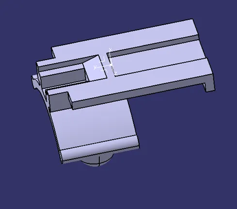
Defining Part as Electrical
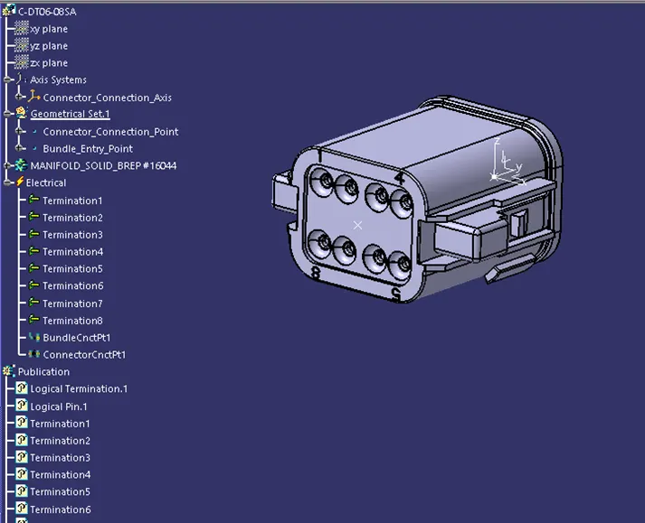
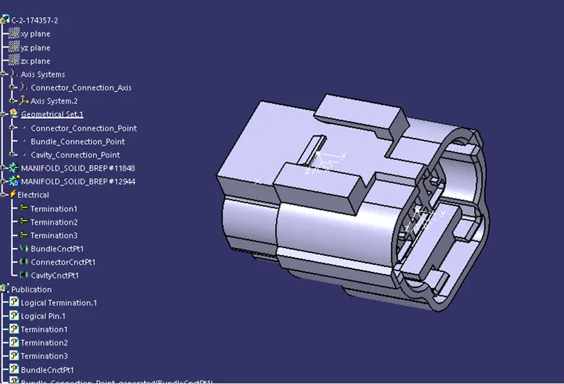
To define the parts for which the geometrical parameters are created as electrical, we need to go to the ‘Electrical Part Design’ workbench. The connectors are defined by selecting the ‘Define Connector command and then clicking on the connector body which gives rise to a pop-up. The pop-up helps in selecting the type of connector and the number of terminals it has. Then the connector connection point, bundle connection points are defined using relevant commands.
- Deutsch DT06 – 08SA:
- Tyco 174357-2
- Tyco 85229-1
Adding the Electrical parts to Catalogue
Finally the electrically defined parts are added to the relevant catalogue and stored in the required directory.