Wiring harness design in CATIA V5 - 3D modeling Week 2 Challenge
Objective :
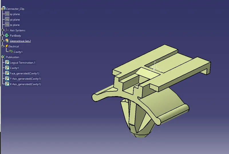
To import 2 connectors and one clip and define the as connectors and clip and give all necessary properties .
Answer:
1. Imported Deutsch DT06 connector to part work bench .
2. Defined the connector connection point and connection axis system .
Point at center of the mating face
Y axis towards direction of mating
X axis towards direction of locking mechanism
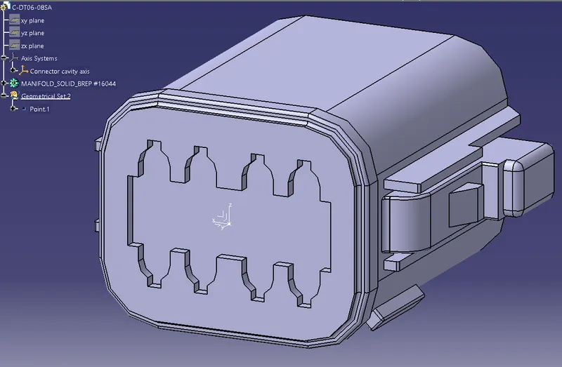
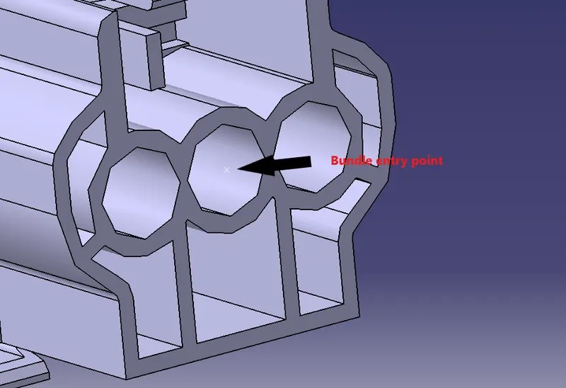
3. Defined the bundle entry point at the center of the face of bundle entry side .
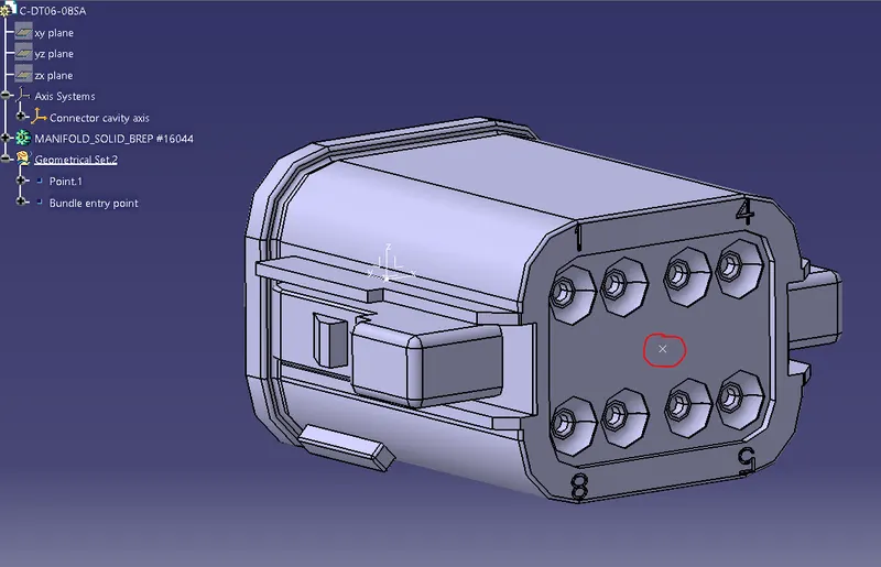
4. Now to define this as a connector , Electrical part design workbench was opened .
Define connector tool was used to define it as a connector
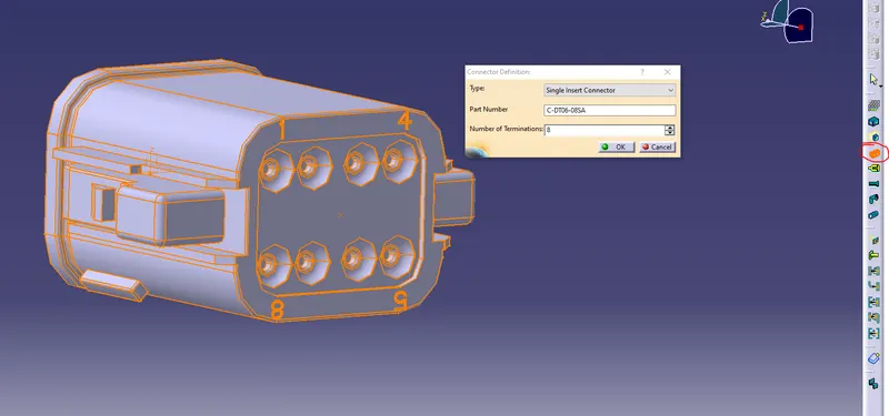
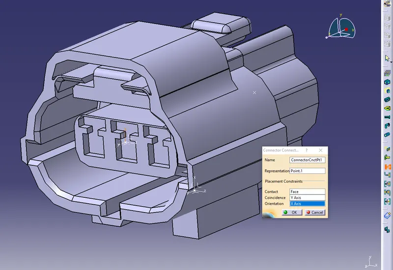
5. Now connector connection point tool was used to define the connection point .
Representation : connection point created in step 2
Contact : Contact face of connector
Coincidence : Y axis
Orientation : X axis
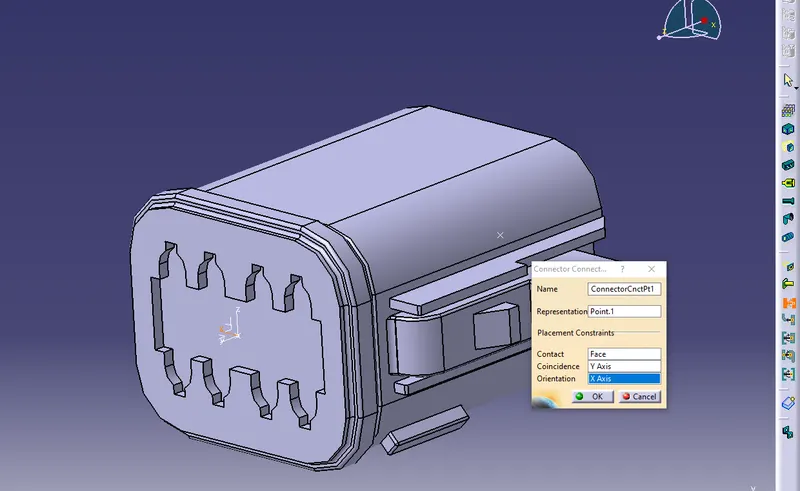
6. Now used to bundle connection point definiton tool to define bundle connection point .
Represenation : Bundle entry face
Point : Bundle entry point
Initial condition : Bundle entry face
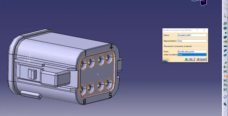
Now we have completely defined the part as a connector with all necessary input .
We can observe that all properties and publications have been made in the part tree .
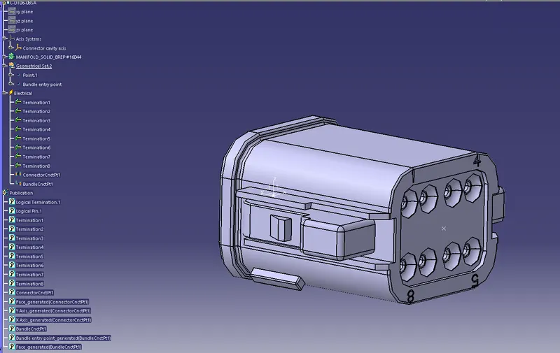
Similarly Steps 1- 3 were done for the Tyco 174357-2 female connector to define connection entry and bundle entry points .
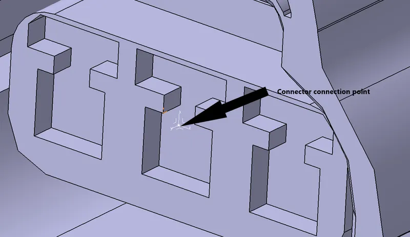
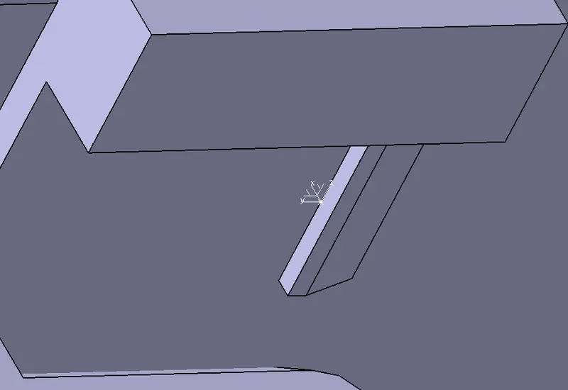
7 . Now to define cavity connection point , a midpoint was created on the edge to mating face of clip .
An axis system was created with origin at this point .
Y axis towards mating direction
X axis towards lock clip direction .
Now step 4-6 was performed on the female connector to define it as a connector and define connector connection point and bundle entry point .
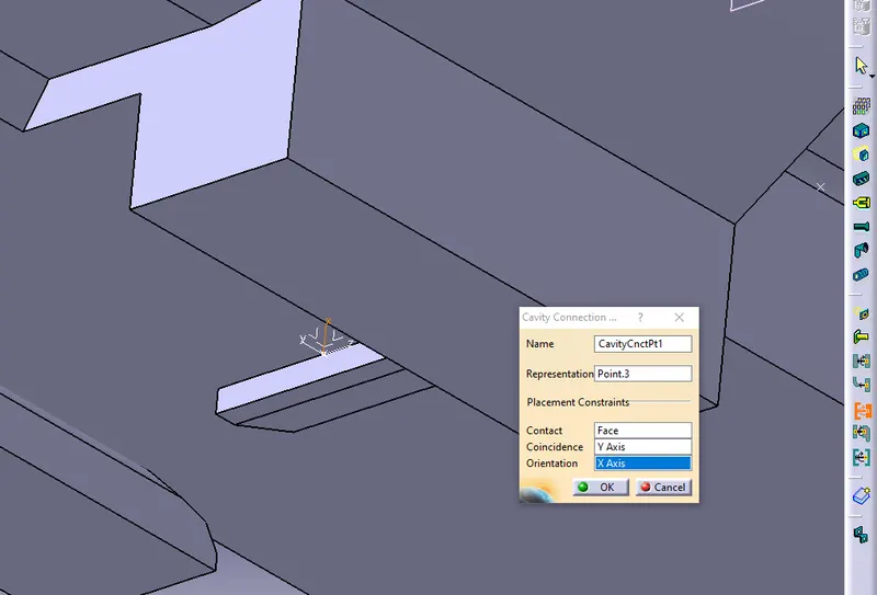
To define cavity connection point , cavity connection definition tool was opened body was selected .
Representation : point defined on step 7
Contact : Face on step 7
Coincidence : Y axis in step 7
Orientation : X axis on step 7
Now we have completely defined the female connector Tyco 174357-2 with all necessary properties and publications
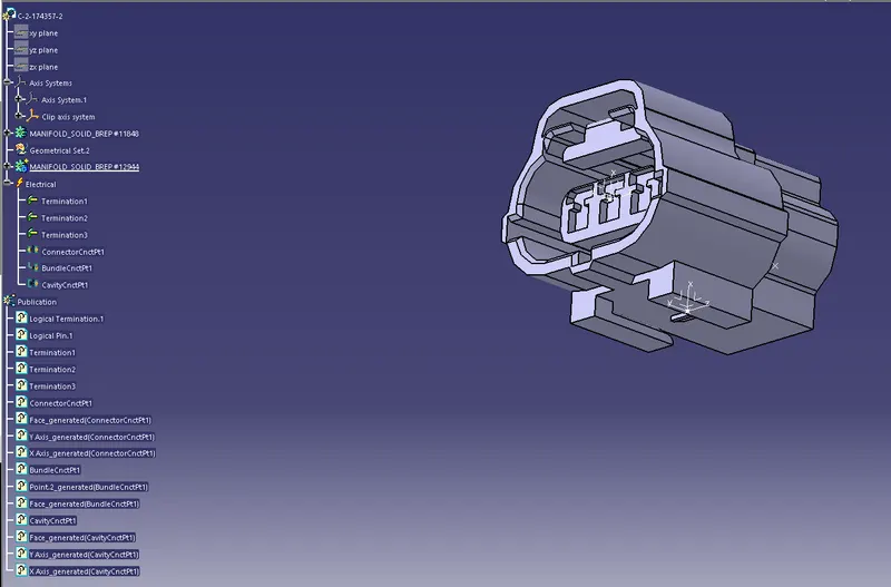
Now to define the mounting clip Tyco 85229-1 .
8.
The part was imported to CATIA on part workbench .
Now create a point at center of mating edge .
Create an axis system at this point which matches the axis system in female connector .
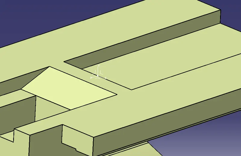
Now go to electrical part design workbench
Select define mounting equipment tool . select the cad to highlight the clip . Click Ok .
Select the define cavity tool and click on the clip .
On the newly opened dialogue box , Representation : Point in step 8 . Contact : mating face . Coincidence : Y axis . Orientation X axis .
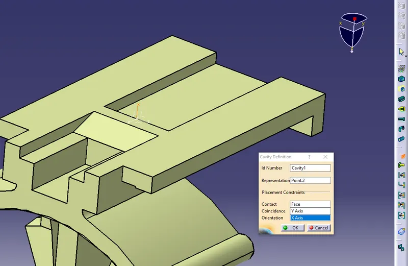
Now we have completely defined the connector as mounting equipment with all required properties and publications .