Week 9-Challenge
Objective : To create connectors and attach various parts of the given model as per given types .
Procedure :
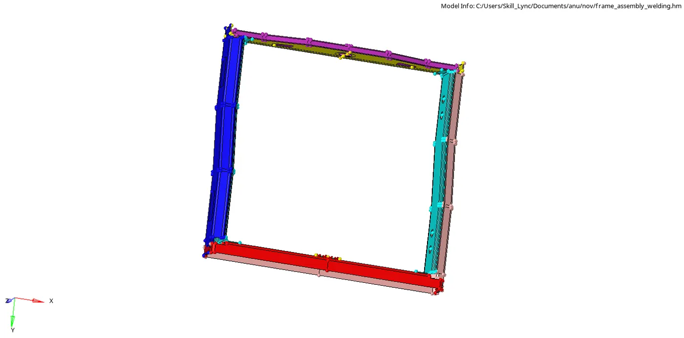
The given model was imported and visually inspected.
All the components were meshed with target element length of 5 by automesh option in 2D module. Tria elements were removed from free edges using Drag tria and swap edge function from quality index of 2D module .
1) Right rail2 and front truss 1 were connected using connectors function from 2D module. In connectors , seam option was chosen and location was set by node list with option to retain nodes clicked on . Spacing was set to 5 as it has to match with target element length . The components were chosen and tolerance was set to 10 . The connector type was selected to be seam-quad(angled+cap+L) and connectors were created after selecting respective nodes.
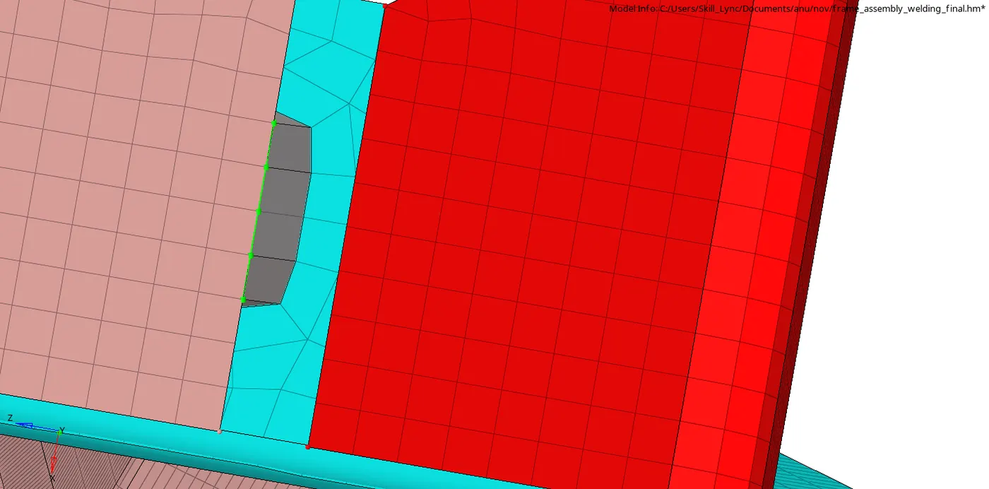

2) Left rail 2 and front truss 1 were selected as components . Connector type was selected as quads . All the other parameters were kept same as of above and connectors were created after selecting repsective nodes .
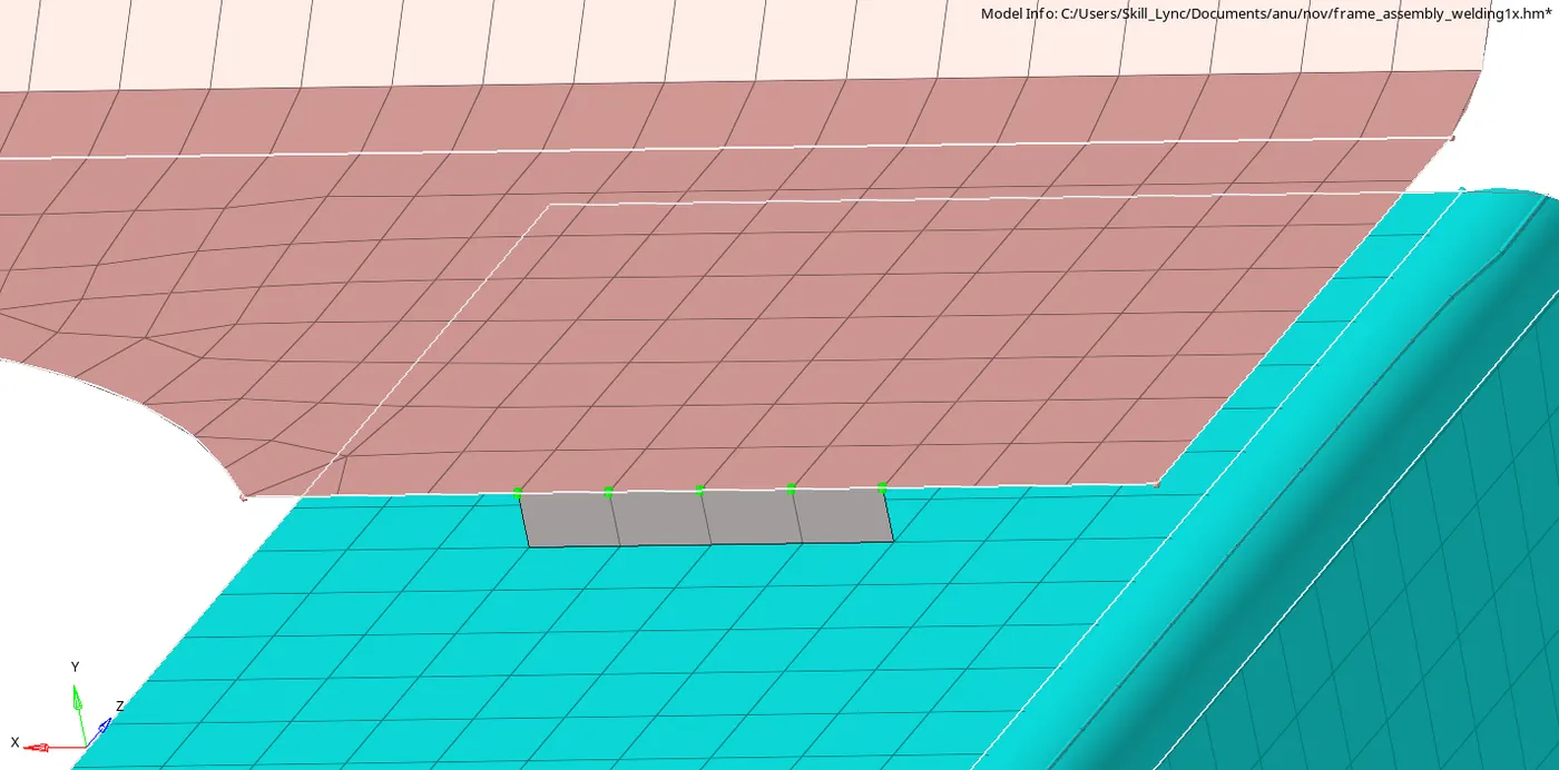

3)Spot option was chosen from connectors in 2D module . Front truss 2 , Font truss 1 and right rail 1 was selected as components . Number of layers were set to 3 and diameter was entered to 5mm. Spacing was set to 5 and nodes retain option was on . Connector type was selected as weld and connections were created after selecting respective nodes.
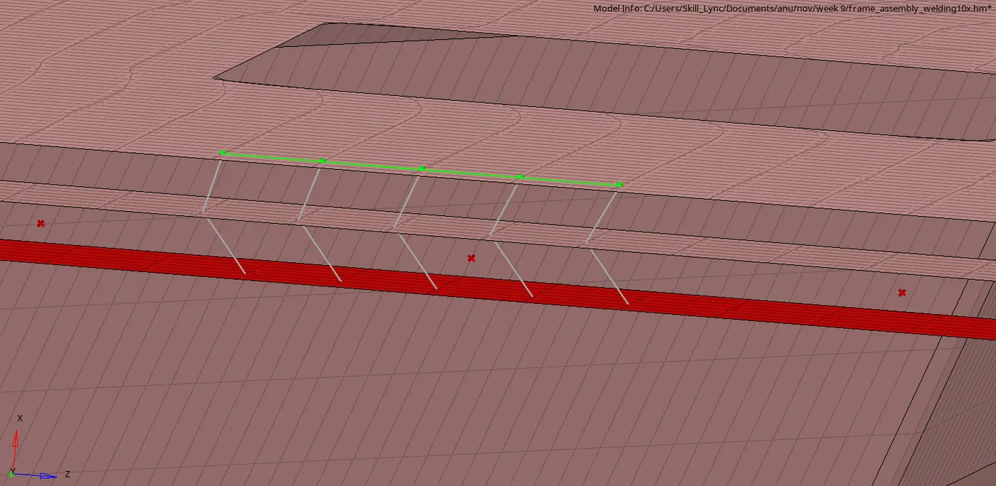

4)Seam option from connectors were chosen and location was set to node list with node retain option on . spacing was set to 5 and tolerance was set to 15 . Front truss2 and front truss 1 were selected as components . Connector type was set as hexa adhesive and connections were created after selecting respective nodes. Then , The same procedure was repeated with Front truss 1 and left rail 1 as components.
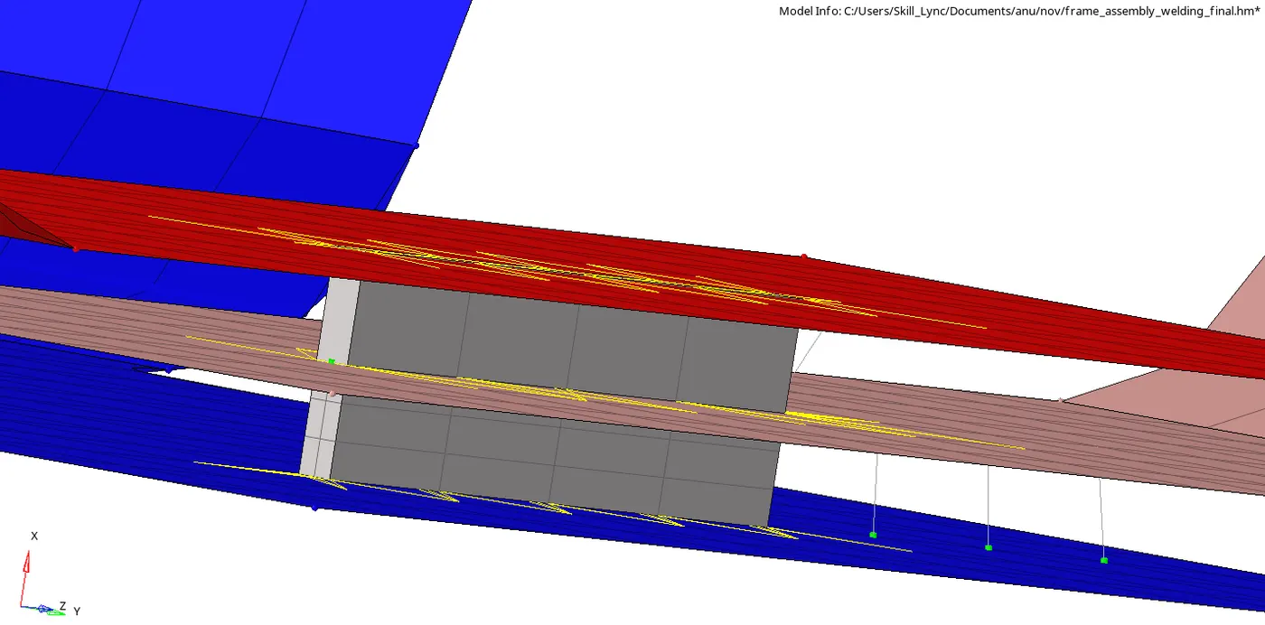

5)Format was changed to Radioss . Rear truss 2 and right rail 2 were selected as components . Tolerance and spacing was set to 15 and 5 . Create hole if none option was chosen and the connection was created after slecting respective node .
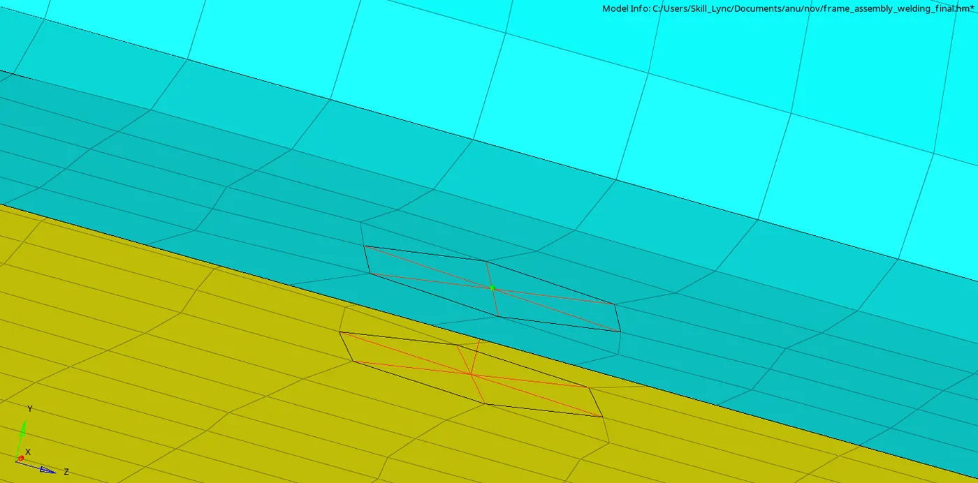

6) Step 5 was repeated with Rear truss 2 and left rail 2 as components .
7) Format was changed to optistruct . Right rail 1 and Right rail 2 were chosen as components . Spot option was chosen from connectors and type was set to Rigid . Tolerance and spacing were entered as 10 and 5 and diameter was entered as 5mm. Connections were created after chosing respective nodes .
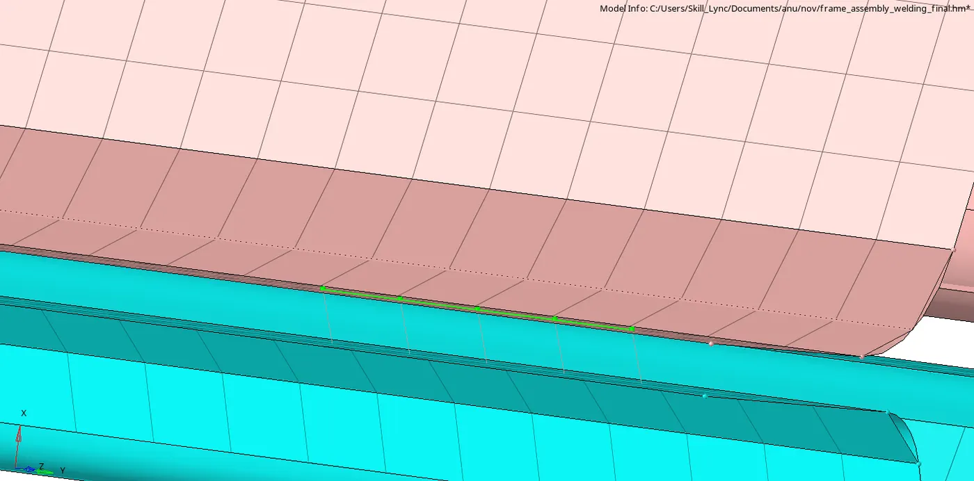

8)Step 8 was repeated while chosing components asleft rail1 and left rail 2 and connector type as spring .
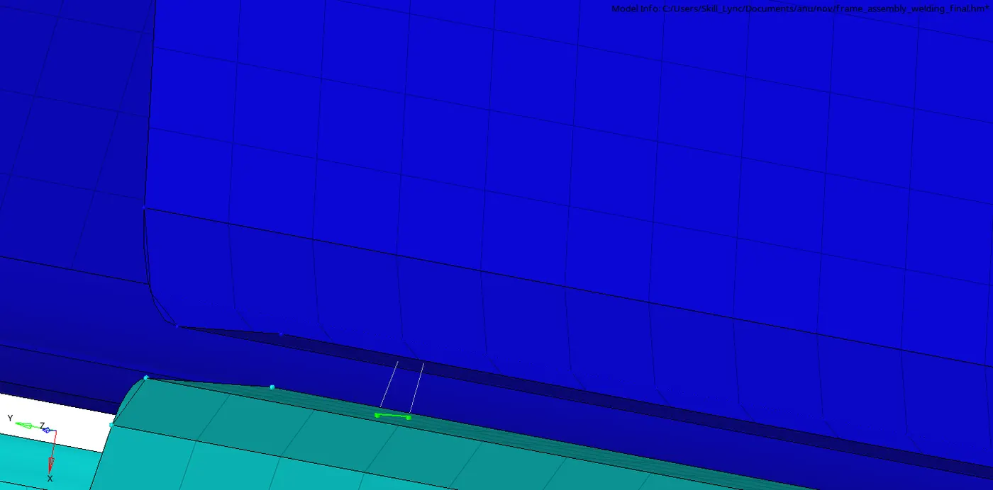

9) All other parts were connected using spot weld option with tolerance , spacing and diameter same as above and type as weld .
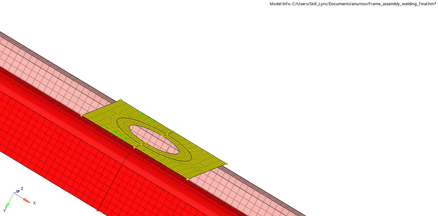
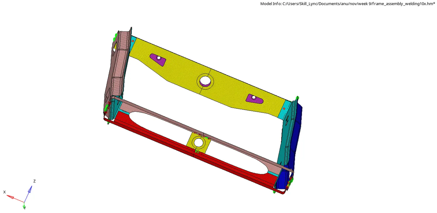
Result : All connections were made and parts were attached as per given criteria .