Week 12 - Project-1
Objective : To follow the quality criteria and mesh the given component and assign thickness .
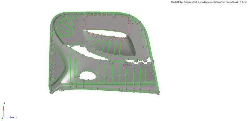
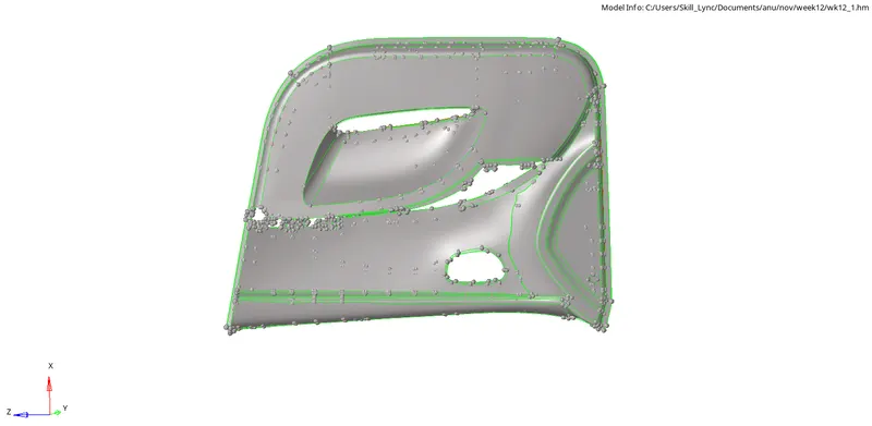
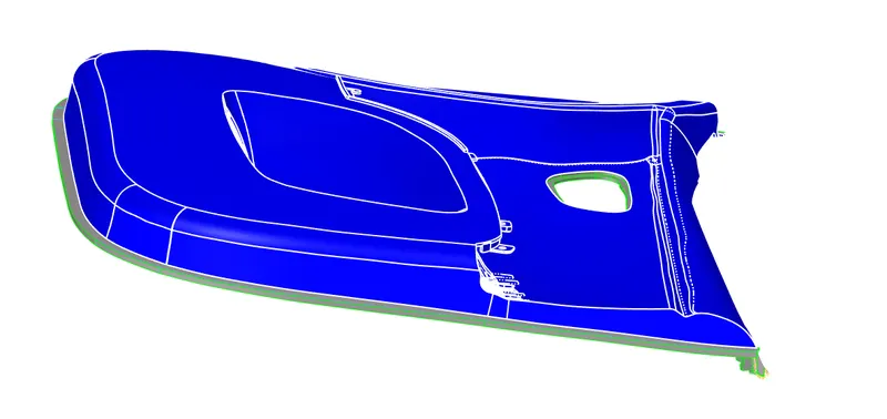
Procedure : The given model was imported and visually inspected for surface deformations.
The geometry colour mode was set to By Topo for identification of free edges .
Step 1 : Geometry Clean up
The free edges on the surfaces and ribs were cleared using toggle edge from quick edit of geometry module . Bodies with thickness greater than 6mm were removed and surfaces filled using filler surface from quick edit .
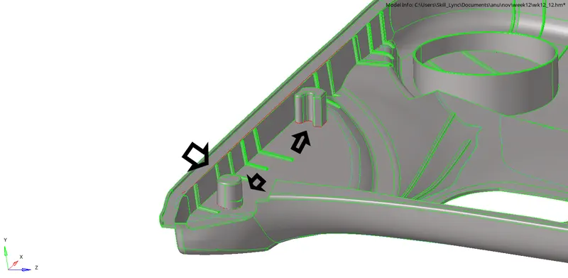
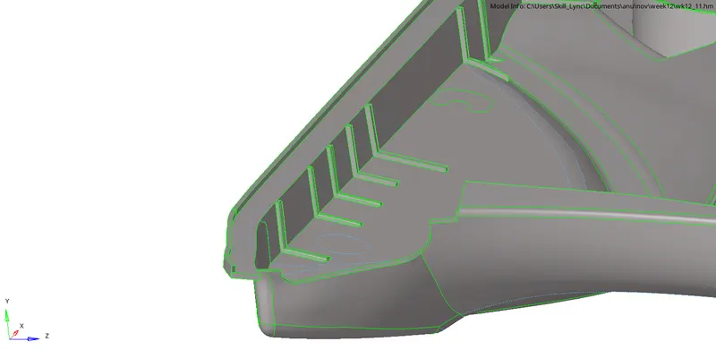



Free edges on ribs were removed by replacing points in quick edit and surface fillet option from defeaturing tool in geometry module . The minimum raduis of surface fillets were reduced to 0.1 units so as to capture very small fillet radius .
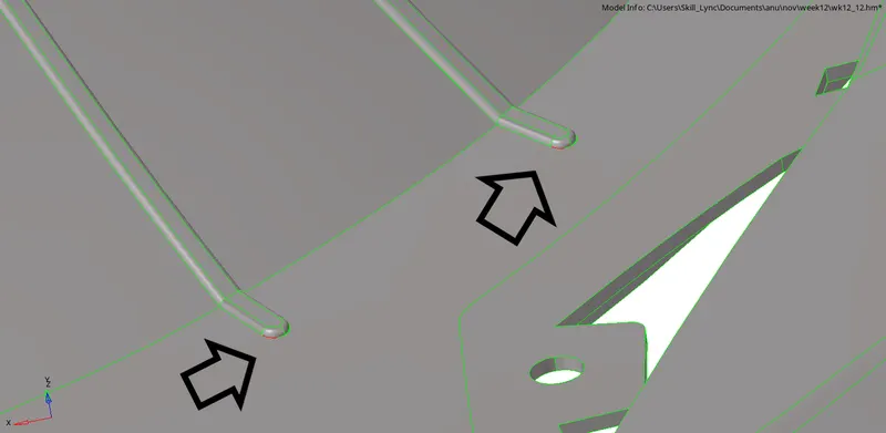
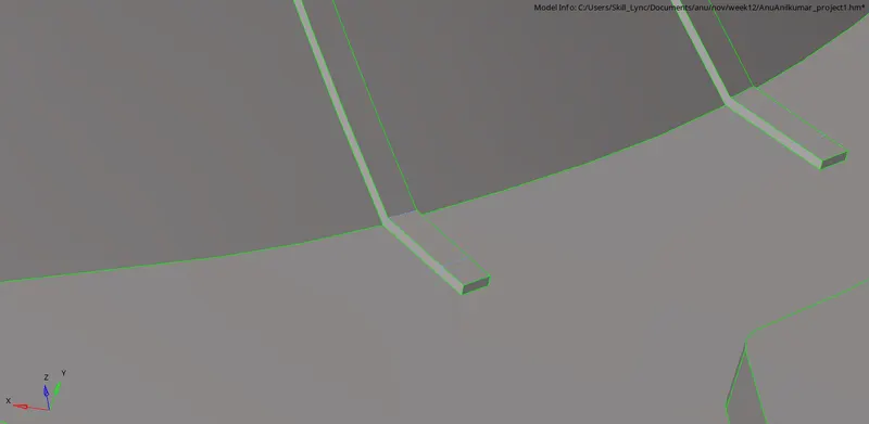


The gaps in surfaces were filled by deleting extra surfaces and creating new surfaces using ruled surfaces option from surfaces panel of geometry module .
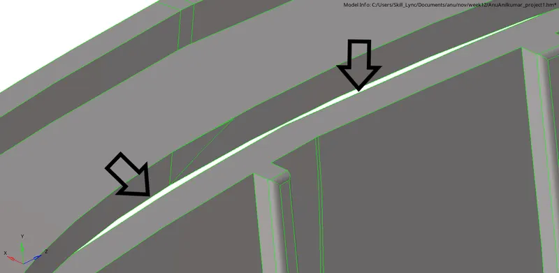
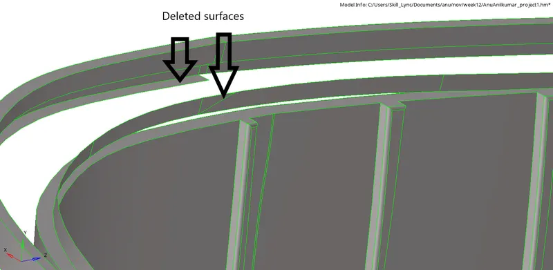
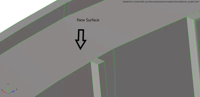

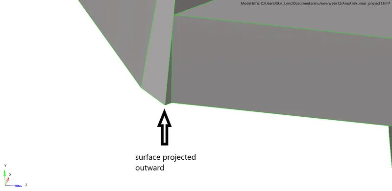
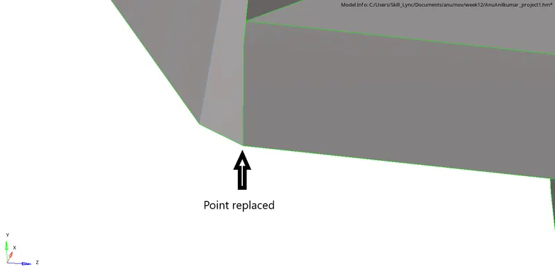
Unwanted surfaces projected outwards were cleared usig replace points from quick edit panel of geometry module .
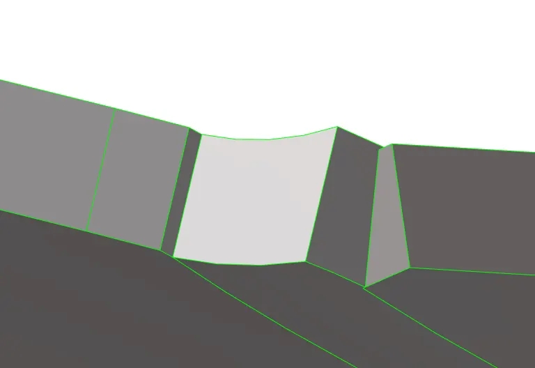
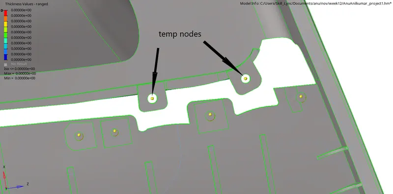
Geometry clean up was performed near mounting holes . A temporary node was created as the centre for each hole using arc centre , lines option from nodes panel in geometry module .

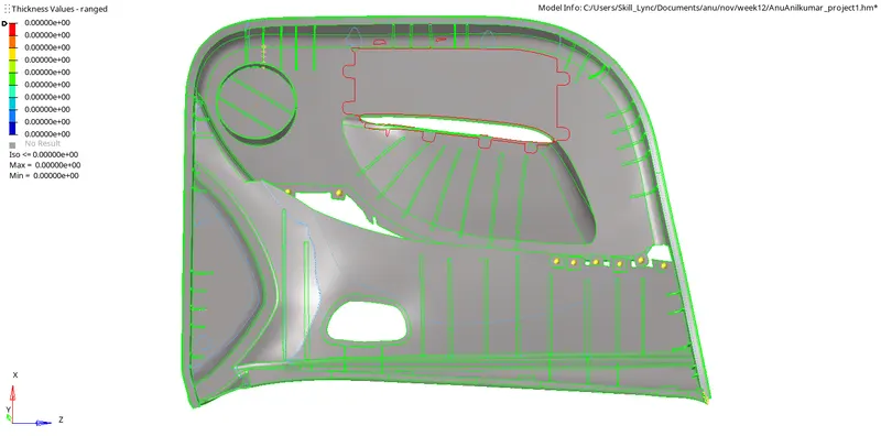
Thus geometry clean up was completed on the component and was ready for extracting midsurface.
Step 2 : Midsurface
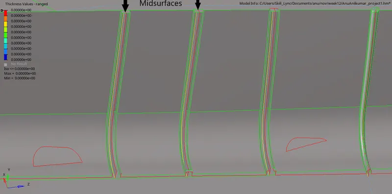
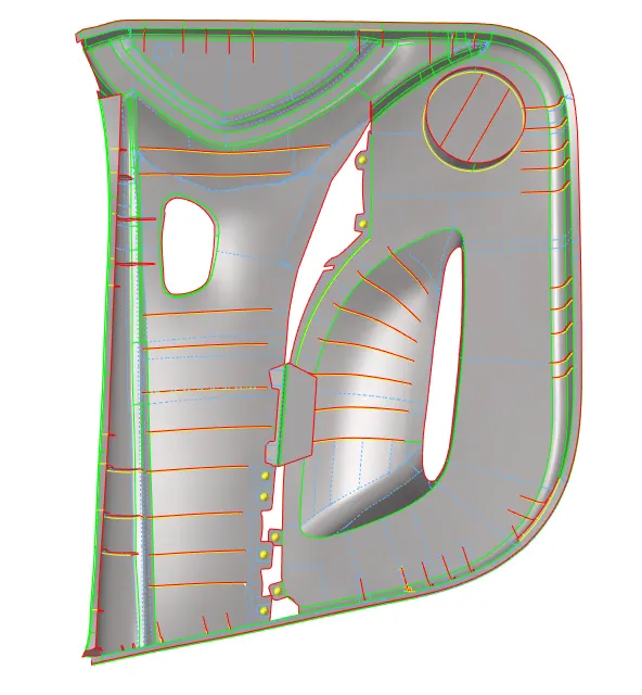
Midsurface for the component were obtained using multiple tools , as the component is of varying thickness . Thickness was found out using ditance between points option from distance panel in geometry module . The midsurface for the entire component was created part by part and was moved to a single component using organise function from tools panel .
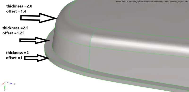
The midsurface of the outer side of the door panel was extracted using offset option from surface edit of geometry panel . Off set value was set as half of thickness respectively i.e 1, 1.25 and 1.4 for the thickness of 2, 2.5 ,2.8 respectively . Surfaces were selected acoording to thickness and colour normal was checked before offsetting .
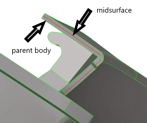
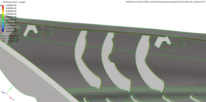
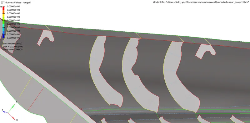

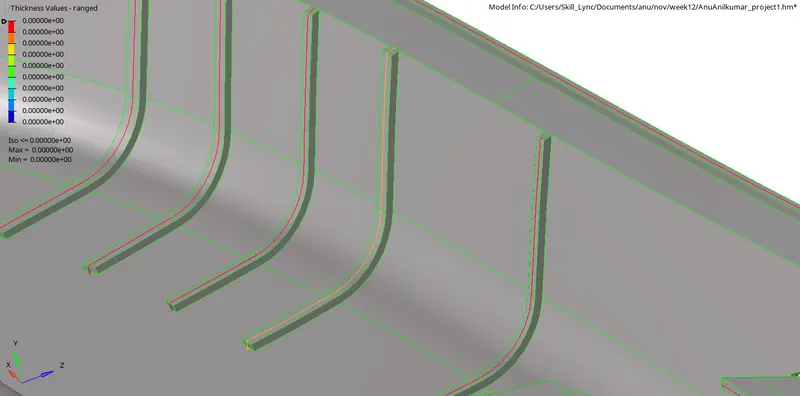
Midsurface of ribs and inner surfaces were created majorly using :
1) final edit tools option from midsurface panel from geometry module to create a midsurface . Use extend option from surface edit to extend the bottom line of this surface to existing midsurface .
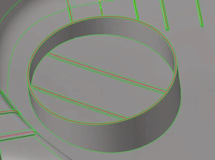
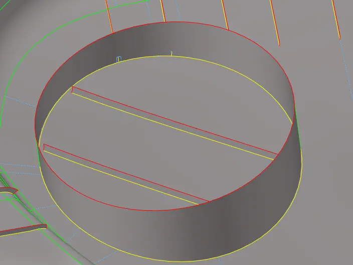


2) Creating a midline using midlines from lines panel in geometry module . Using trim with lines option from surface edit to mark a line on midsurface and create a surface between the trimmed line and midline .
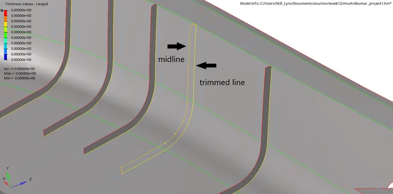
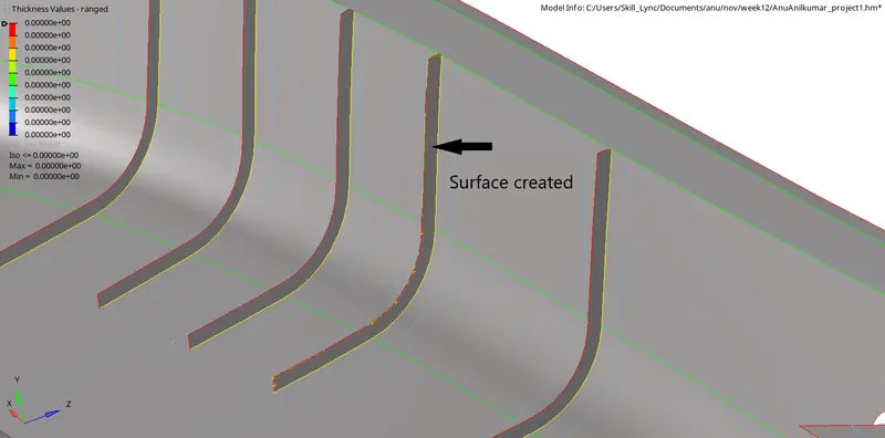


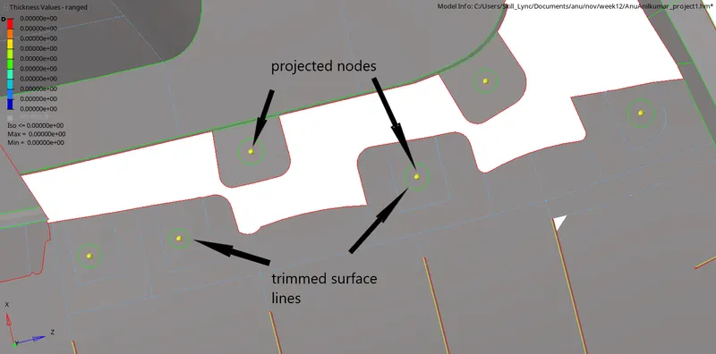
Midsurface for mounting holes were created by creating a circle of same radius using nodes projected using project function from tools module . Circles were created using circle centre and radius option from lines panel of geometry module using these nodes as centres The surfaces were then trimmed using trim with free lines option from surface edit . The surface inside circle was deleted using delete surface option from delete panel so as to create holes.
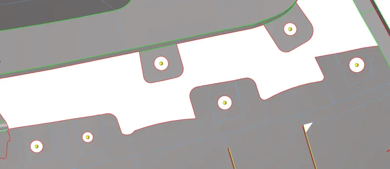


The extracted midsurfaces were extended using extend surface option from surface panel from geometry module . The additional extended surfaces were trimmed and deleted using trim with self intersecting surfaces option from surface edit panel from geometry module .

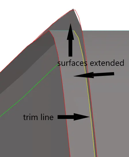
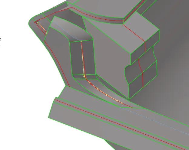
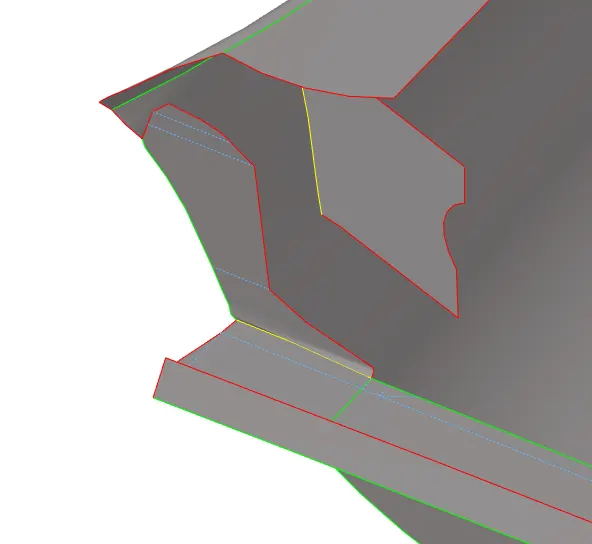
Thus midsurface for the entire component was created .
Step 3 :Meshing as per the given quality criteria
To Mesh the component as per given quality criteria , the given values were entered using crtiteria file settings option from preferences panel .
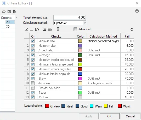
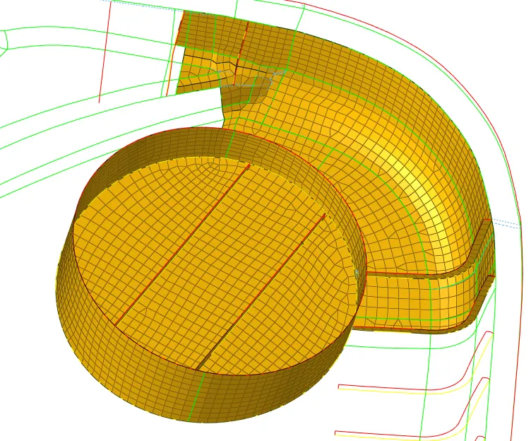
The surfaces were selected part by part and meshed using automesh option in 2D module . The target element length was given as 4 , type was chosen as mixed and allign and size options were ticked on .

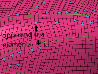
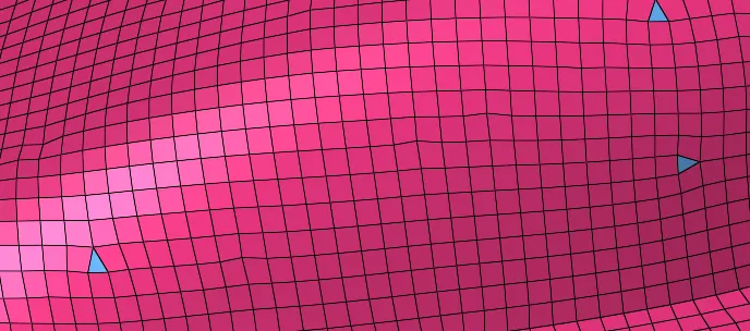
Opposing tria elements were eliminated using drag tria option from clean up tools of quality index panel from 1D module .

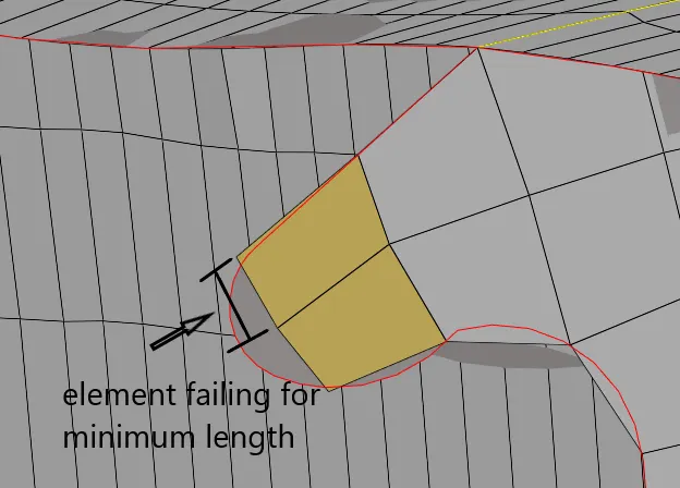
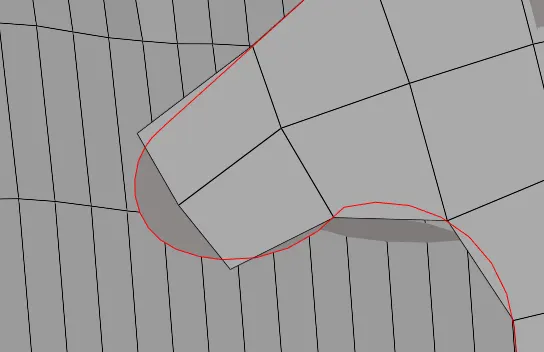
Elements failing for min and max length were rectified using distance option in geometry module . The two nodes option in distance panel allows to adjust the length between 2 nodes so as to meet the qality criteria .

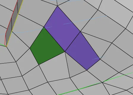
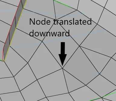
Elements failing for warpage was rectified using translate node option from tool module . The translate node option allows to move single or multiple nodes in a wasy so as to reduce the warpage to meet the quality criteria .

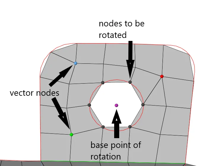
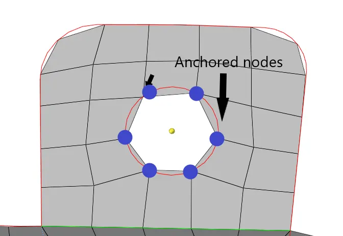
To get proper mesh flow around holes , the surface is first meshed with the number of nodes on hole an even number according to size of mesh . Rotate tool from tool module is used to select nodes to be rotated , so as to make edge of polygon inside hole to be parallel with nearest surface edge . Then the whole surface is remeshed by anchoring the nodes in the hole area .


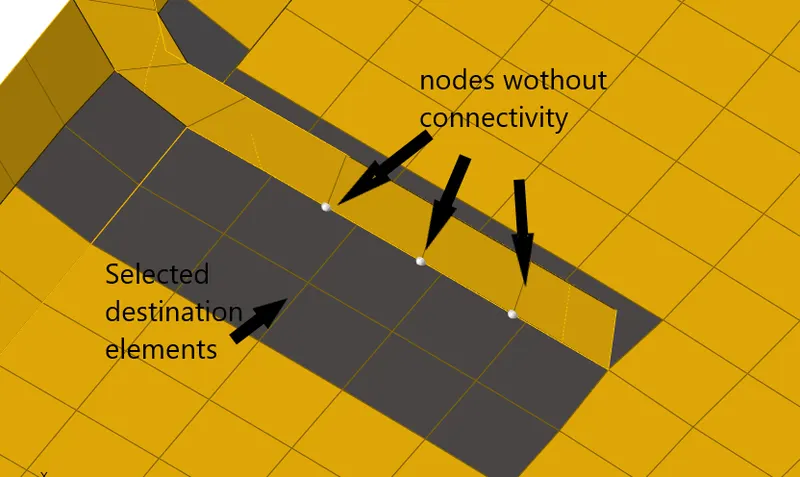
Elements on ribs which did not have connectivity with surface ribs were rectified using mesh edit option from 2D module . In mesh edit , the imprint option was used to allign selected node list to be imprinted onto destination elements .
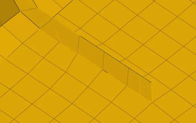

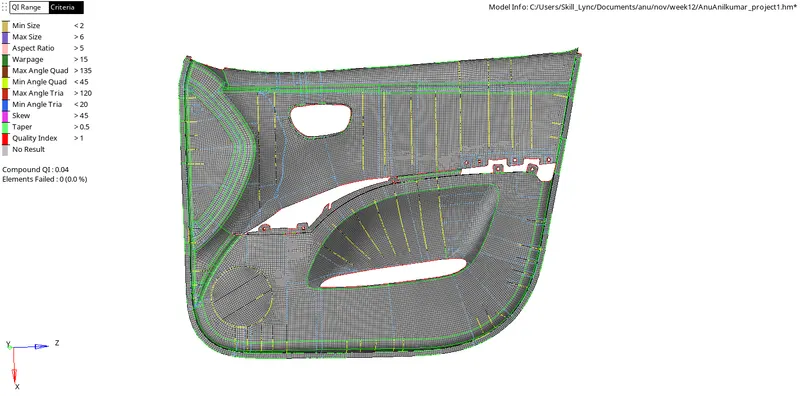
Thus the component was meshed as per given quality criteria with zero element failure . 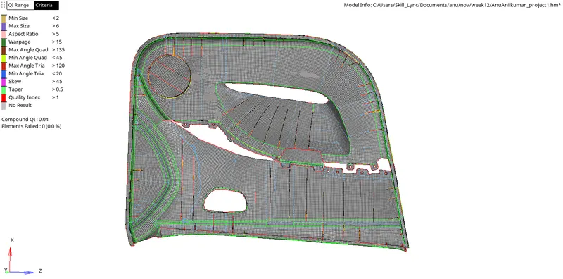
Step 4 : Assigning Thickness
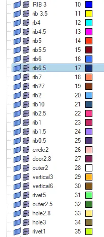
To assign thickness to elements , new components were created and named according to the thickness from parent component . All elements were moved from meshed component to new components as per their respective thickness from parent component using organize function from tools module . For ribs having multiple thickness , the elements were individually selected and moved to new components according to respective thickness.

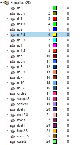
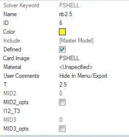
New properties were created and named according to the thickness of components . Thickness value were assigned to each property . Each component were assigned to each property according to their thickness by right clicking on each component and using assign function .
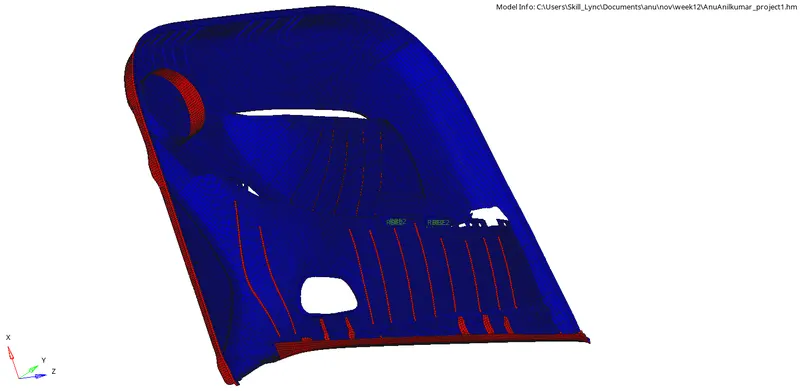
To check the element normal , the normal panel from tools module was selected , the displayed 2D elements were chosen and normal was checked . Adjust option was used to correct normals which were in reverse direction .

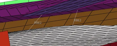
The plastic rivet was connected to side panel body using RBE2 elements . To make connection , rigids panel from 1D module was chosen and nodes were selected from both surfaces . The element type was chosen as RBE2 and connection was created .

The element colour mode was changed to by component to display elements as per their thickness .
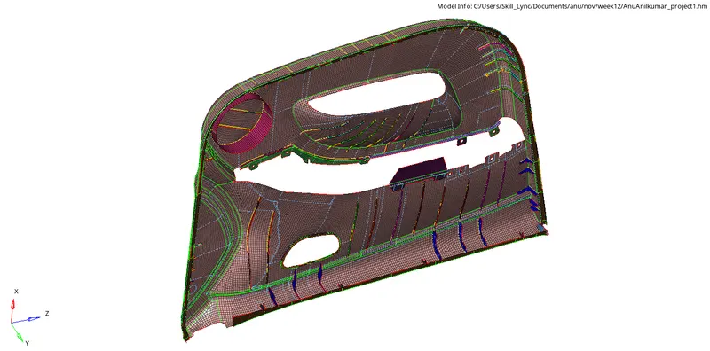
The element colour type was changed to by property and element representation was changed from traditional 2D representation to 2D detailed element representation so as to display thickness of elements .
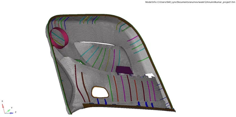
Result :
1) Geometry clean up was performed on the given component so as to remove any unwanted free edges and surface deformations.
2) Midsurface of the component was extracted .
3) The component was meshed according to given element quality criteria with zero elements failure .
4) Thickness was assigned to the component .