Wiring harness design in CATIA V5 - 3D modeling Week 2 Challenge
Aim:
Electrically defined the given connecters and connecter clip with the help of geometry and assemble by the electrical wiring harness workbench.
WIRING HARNESS
A wiring harness, also known as a wire harness or cable assembly, is a bundled collection of wires, cables, and connectors that are used to transmit electrical signals and power between various components or devices. It is a common component in many electrical systems, including automotive, aerospace, industrial machinery, and electronics.
The primary purpose of a wiring harness is to provide a centralized and organized method of connecting different electrical components within a system. Instead of individual wires running separately, a wiring harness groups and routes the wires together, typically with some form of protective covering or insulation. This arrangement offers several advantages, including improved reliability, easier installation, reduced electrical interference, and enhanced safety.
Wiring harnesses are often custom-designed to meet specific requirements of a particular application. They can vary in complexity from simple harnesses with just a few wires and connectors to highly intricate assemblies with hundreds or even thousands of wires. The wires within a harness are typically color-coded to facilitate easier identification and connection during installation or maintenance.
In addition to wires, a wiring harness may include other components such as terminals, connectors, splices, fuses, and protective sleeving. These elements help ensure secure connections, provide strain relief, and protect the wires from environmental factors like heat, moisture, abrasion, and electromagnetic interference.
Wiring harnesses are manufactured using specialized equipment and techniques. Automated processes such as cutting, stripping, crimping, soldering, and heat shrinking are commonly employed to ensure consistent quality and reliability. Quality control measures, including electrical testing, are also implemented to verify the integrity of the finished harnesses before they are deployed in various applications.
Overall, wiring harnesses play a crucial role in modern electrical systems by providing a structured and efficient means of connecting and transmitting electrical signals between components.
Connecters:
It is connecting electrically one function with another or connect the wires.
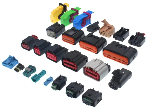
Clips:
Generally, clips are mounding some parts. In this model clips are mounding the connecters.
Tools:
For electrically define some create some geometries and electrical part design tools.
Mechanical part work bench:
Point:
It indicates one location. This tool is used to create between two points in the centre of face.
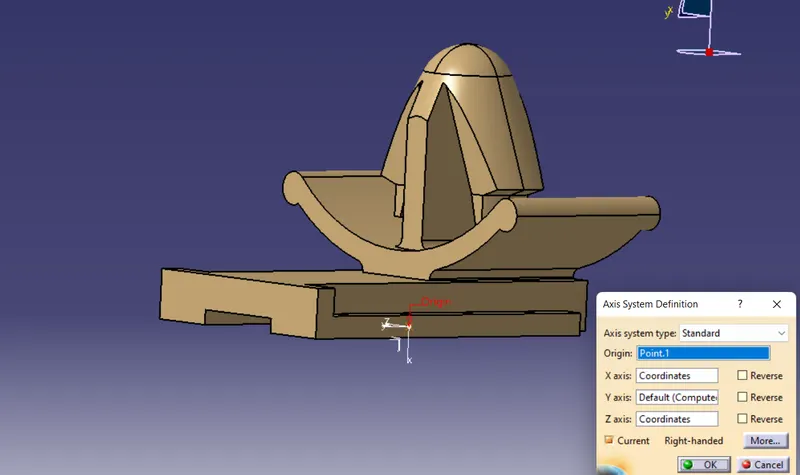
Axis system:
It is fixed on a point and give X, Y, Z direction and plane in the location which is used to define and assemble the electrical parts.
Electrical part work bench:
Define connecters:
This option is used to define the connecter with buddle entry points. After this process CATIA will take the part as connecter.
Define mounding equipment:
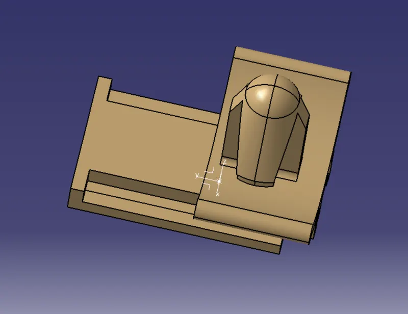
This option is used to define as mounding equipment. After this process it take as mounding equipment.
Define connecter connection point:
This option is used to define the connecter connection point with the help representation, contact, coincident and orientation which are given by point, surface and axis system.
Define bundle connection point:
This option is used to define the bundle entry point of connecter with the help representation, contact, coincident and orientation which are given by point, surface and axis system.
Define cavity connection point:
This option is used to define the cavity connection point of connecter with the help representation, contact, coincident and orientation which are given by point, surface and axis system.
Define cavity:
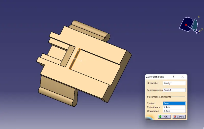
This option is used to define the cavity connection point of mounding equipment with the help representation, contact, coincident and orientation which are given by point, surface and axis system.
Electrical assembly:
Connect electrical device:
This option available in electrical assembly bench. This option is used to connect the two electrical devices. Arter defines the electrical device if we click the part it automatically assemble with help of point, axis, face of surface from electrical define.
Disconnect electrical device:
This option is used to disconnect the two electrical devices from connected devices.
Methodology:
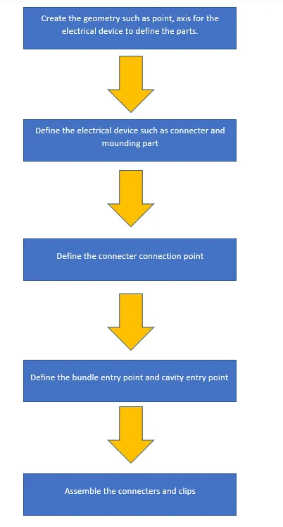
DESIGNING
connectors & Connector clip cad data
- Deutsch DT06 – 08SA ( https://www.te.com/usa-en/product-DT06-08SA.html)
- Tyco 174357-2 (https://www.te.com/usa-en/product-2-174357-2.html?source=header-match)
- Tyco 85229-1 – (https://www.te.com/usa-en/product-85229-1.html?q=85229&source=header)
CONNECTOR 1(Deutsch DT06 – 08SA)
1. First create the geometry such as point, axis to define the electrical device.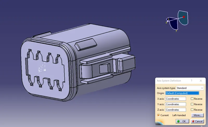
2. Then define the connecter with bundle entry point.
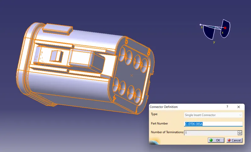
3. Then give connecter connection point. 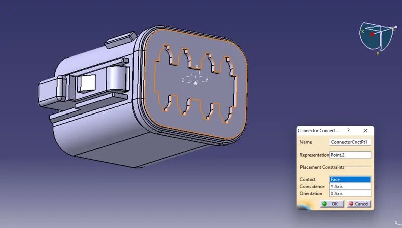
4.Finally, give buddle entry point and save in catalogue.
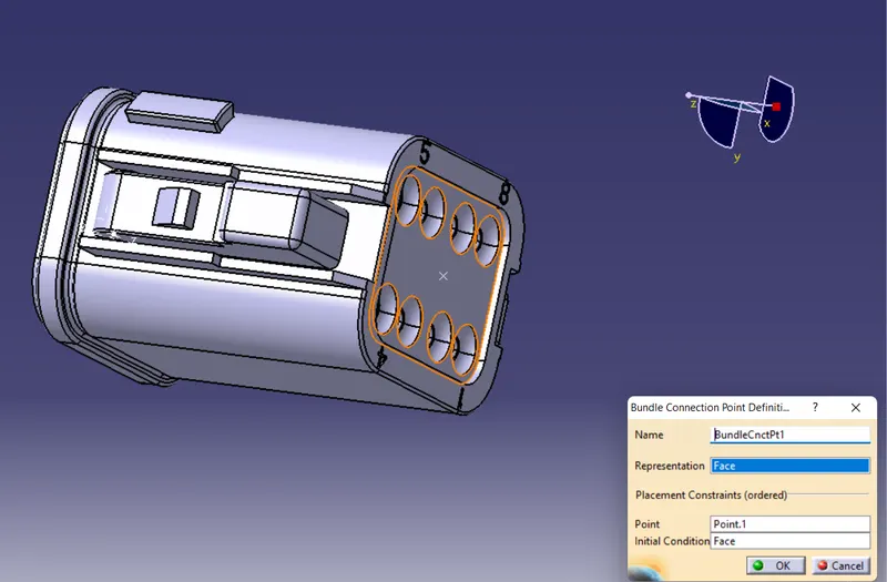
Connecter 2(Tyco 174357-2)
1.First create the geometry such as point, axis to define the electrical device.
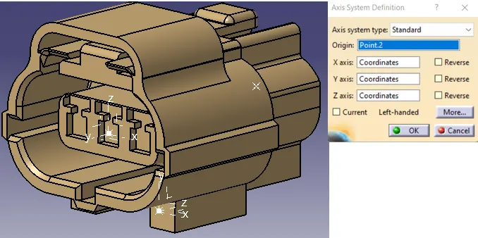
2.Then define the connecter with three bundle entry point.
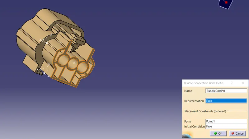
3.Give buddle entry point of connecter.
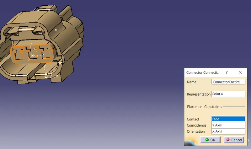
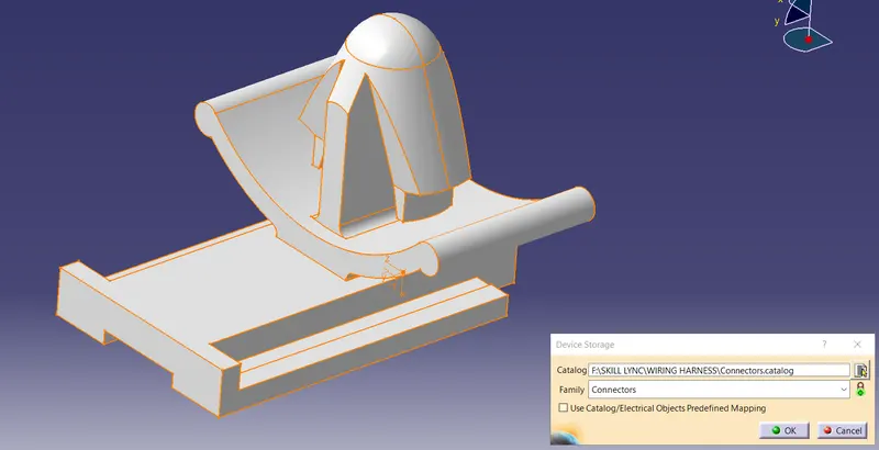
CLIP
First, create the geometry such as axis, point.
Then define a part as mounding equipment.
Then define the cavity with help of axis, faces and point.
Finally save in the catalogue.
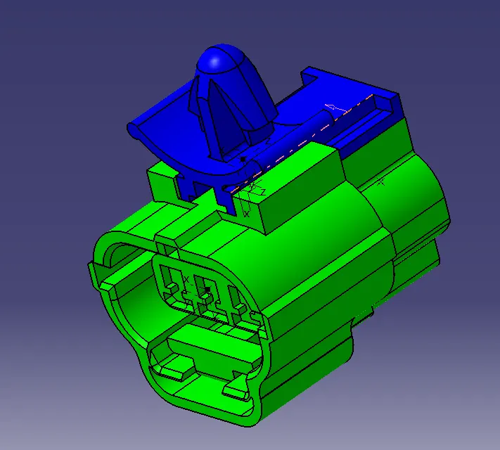
ASSEMBLY
Assemble the connecter 2 and clip with help of connect electrical
Conclusion:
Given connecters and clips are successfully electrically defined and assembled the connecter and clip by the help of CATIA.