Wiring harness design in CATIA V5 - 3D modeling Week 2 Challenge
Wiring Harness Design in CATIA V5- Week 2 challenge
AIM:
To define the following connectors and the associated connector clip CAD data from the provided link, categorizing them as Electrical Connectors. Utilize the Electrical Part Design Workbench to incorporate all necessary properties related to the Connectors and Clip.
INTRODUCTION:
- Wiring Harness:
A wiring harness, commonly referred to as a cable harness or wiring loom, constitutes a comprehensive assembly of wires, connectors, and various electrical components, collectively forming an integrated electrical system. This assembly is primarily utilized for the transmission of electrical signals and power among diverse components within vehicles or machinery.
Wiring harnesses are meticulously designed to ensure reliable and secure connections between numerous electrical elements, while simultaneously minimizing the potential for electrical interference or signal degradation. The complexity and dimensions of wiring harnesses can vary significantly based on the specific application, ranging from straightforward configurations with merely a few wires to intricate harnesses containing hundreds or even thousands of wires.
These harnesses can be tailored for particular applications or produced as pre-manufactured systems suitable for a broad spectrum of vehicles and machinery. Typically, a wiring harness comprises multiple individual wires that are consolidated, either wrapped within a protective sheath or secured with clips and other fasteners to maintain their organization.
In summary, wiring harnesses are essential components in contemporary electrical systems, facilitating the safe and efficient functioning of an extensive array of equipment and devices.
- Vehicle Electrical Distribution System (EDS):
A vehicle electrical distribution system comprises a sophisticated network of wires, connectors, and electrical components that function cohesively to supply power and control signals to various systems and components within a vehicle. This system is essential for delivering power from the battery to critical subsystems, including the engine, transmission, lighting, entertainment systems, and other electronic devices.
The principal components of a vehicle's electrical distribution system encompass the battery, alternator, starter motor, as well as an array of relays and fuses. The battery acts as the primary power source for the system, while the alternator plays a crucial role in recharging the battery and supplying power to the electrical system when the engine is operational. The starter motor initiates engine operation, and the relays and fuses serve to safeguard the system against damage arising from electrical faults and overload situations.
- Wiring Harness Design Process:
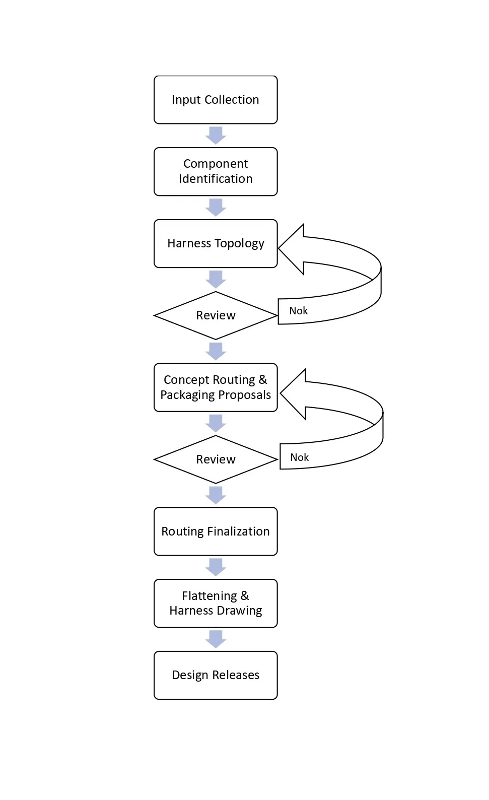
- Wiring harness Assembly Structure – Connector Definition:
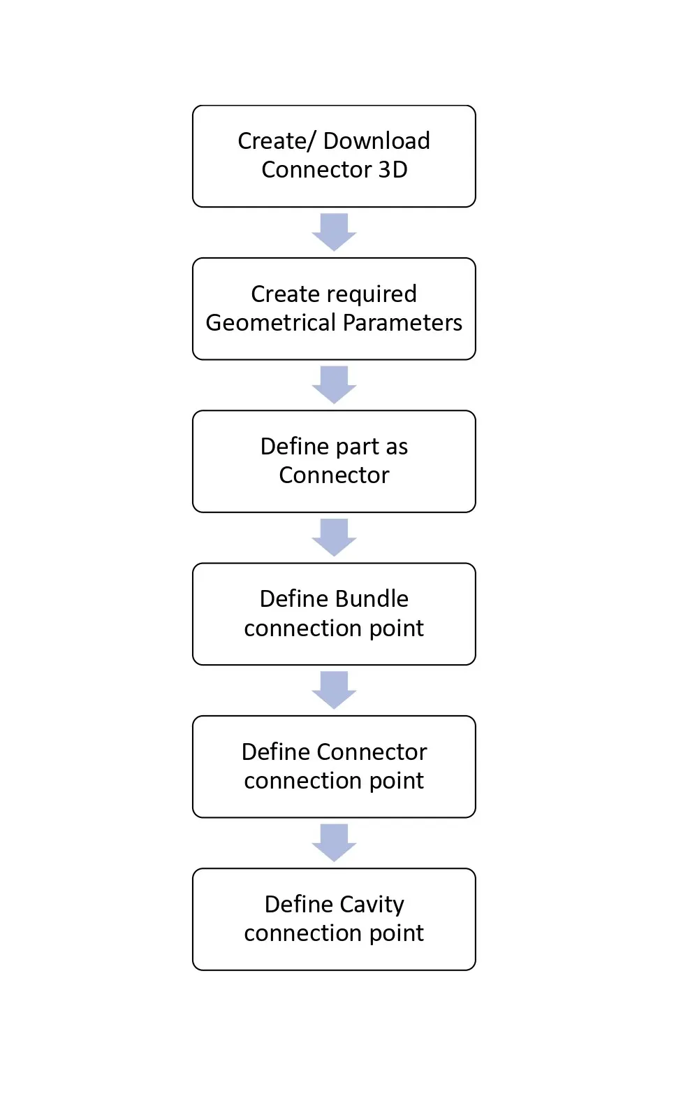
The following parameters are essential for the definition of any connector:
1. Geometry Parameters – This includes the specification of points and the coordinate system (axes).
2. Connector Connection Points – These points facilitate the connection between one connector and another.
3. Harness Bundle Entry Point – This designates the termination point of the harness bundle segment when routed to the electrical connector.
4. Cavity Connection Point (Optional) – This point is utilized to define the connection of a connector to a connector clip. It is pertinent solely to connectors that feature a mounting capability for such clips.
Commands in Electrical part workbench:
- Define Connectors: This option is utilized to establish the connector in conjunction with bundle entry points. Upon completion of this process, CATIA will recognize the part as a connector.
- Define Molding Equipment: This option serves to designate the equipment as molding equipment. Following this procedure, the item will be categorized as molding equipment.
- Define Connector Connection Point: This option is employed to specify the connector connection point. This is facilitated through representations, contact points, coincidences, and orientations, which are defined by points, surfaces, and axis systems.
- Define Bundle Connection Point: This option is used to outline the bundle entry point of the connector. This is achieved through representations, contact points, coincidences, and orientations defined by points, surfaces, and axis systems.
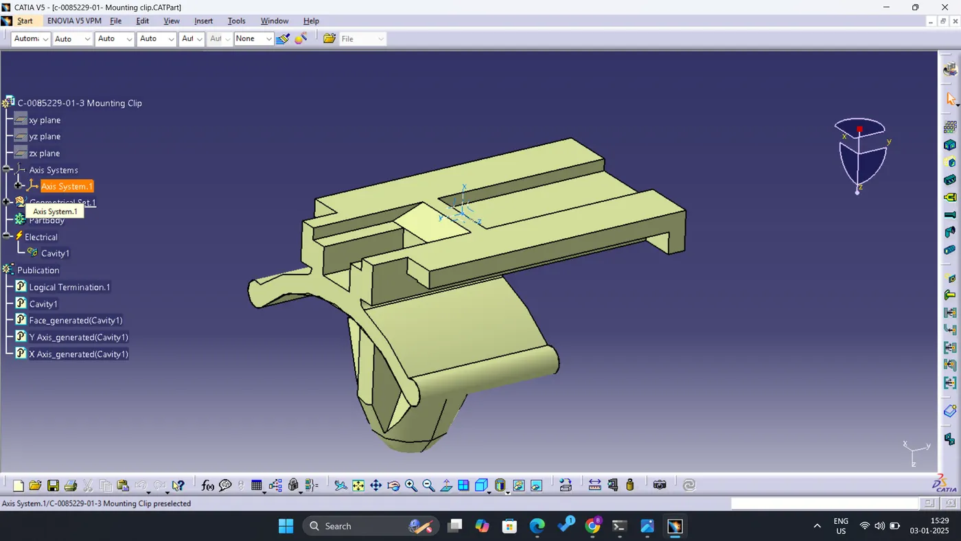
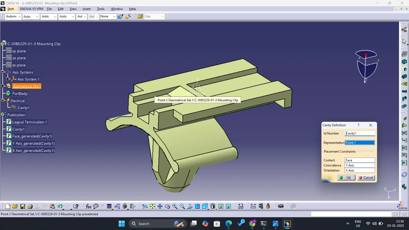
- Define Cavity Connection Point: This option allows for the definition of the cavity connection point of the connector. It employs representations, contact points, coincidences, and orientations determined by points, surfaces, and axis systems.
- Define Cavity: This option is dedicated to defining the cavity connection point of the molding equipment using representations, contact points, coincidences, and orientations specified by points, surfaces, and axis systems.
Commands used in Electrical assembly:
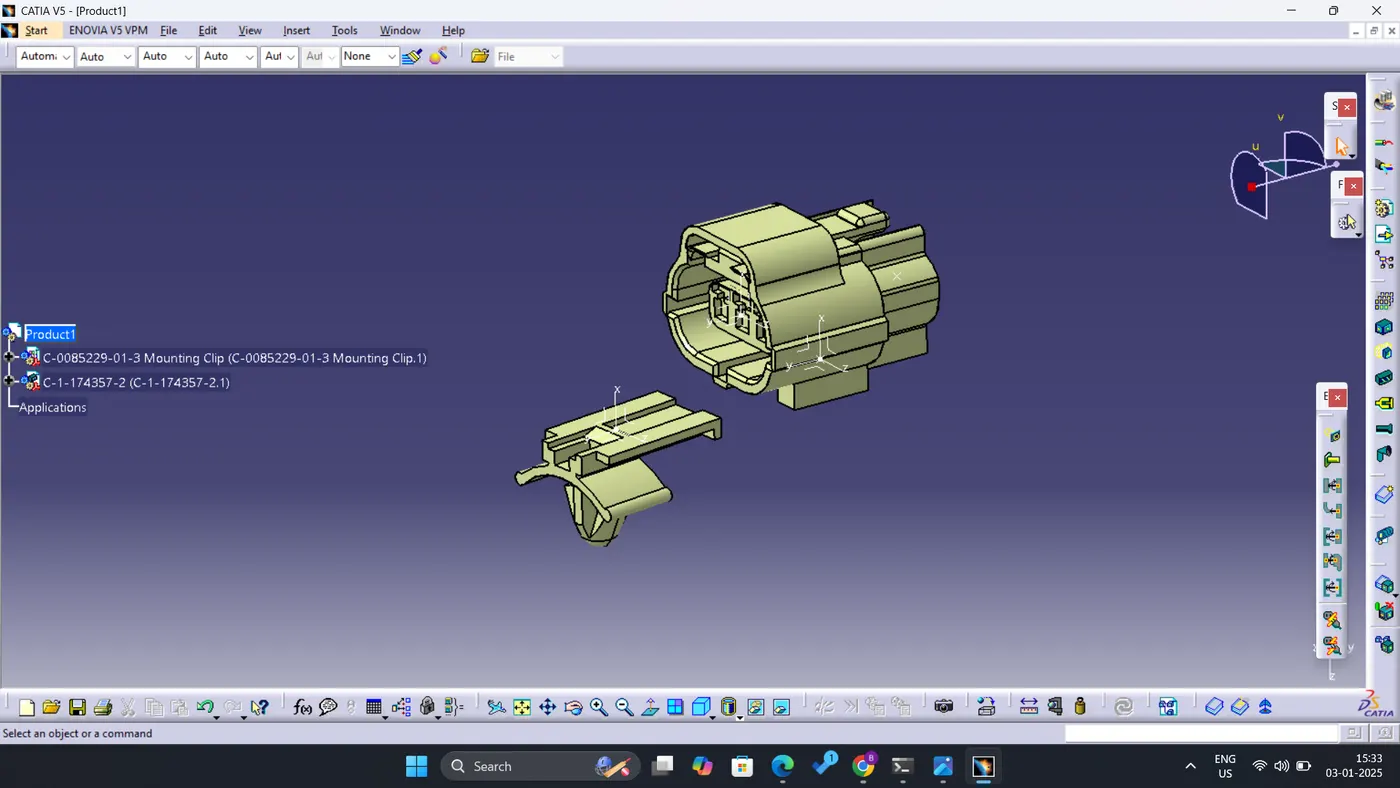
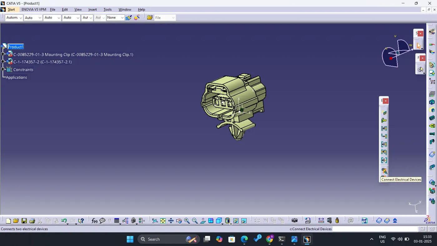
- Connect Electrical Device: This function facilitates the connection of two electrical devices. Once both components are defined in an electrical context, they will be automatically assembled utilizing reference points, axes, and surfaces.
- Disconnect Electrical Device: This function allows for the disconnection of two electrical devices from their connected counterparts.
PROCEDURE
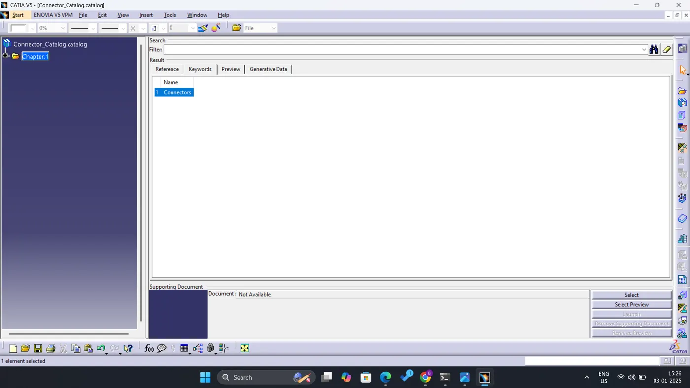
- Creation of catalog.
- Start/ launch Catia software
- Go to File- New- then select Catalog Document
- Select Add Family- Name the catalog and select the file type from drop-down
- Save the catalog at the desired location.
- Connector Definition:
- Download 3D file of Deutsch DT06 – 08SA from te.com.
- Open Deutsch DT06 – 08SA in ‘Part Design’ Workbench.
- To create a connector connection point and Connector Connection Axis, first Create a midpoint on the contact face which will be normal to the wire bundle insertion and Connector insertion.
- Create an Axis System concerning the point which we have created and define the axis direction.
a. The Y-Axis should be oriented towards the connector's front face.
b. The X-Axis should be oriented towards the clip's locking mechanism.
c. The Z-axis should be pointing across the connector from left to right.
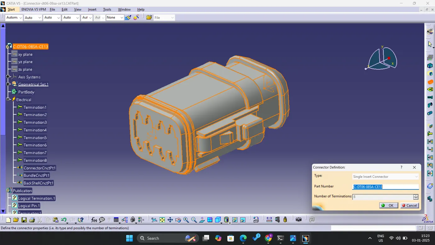
- Define part as a connector-
- Switch to Electrical Part Design.
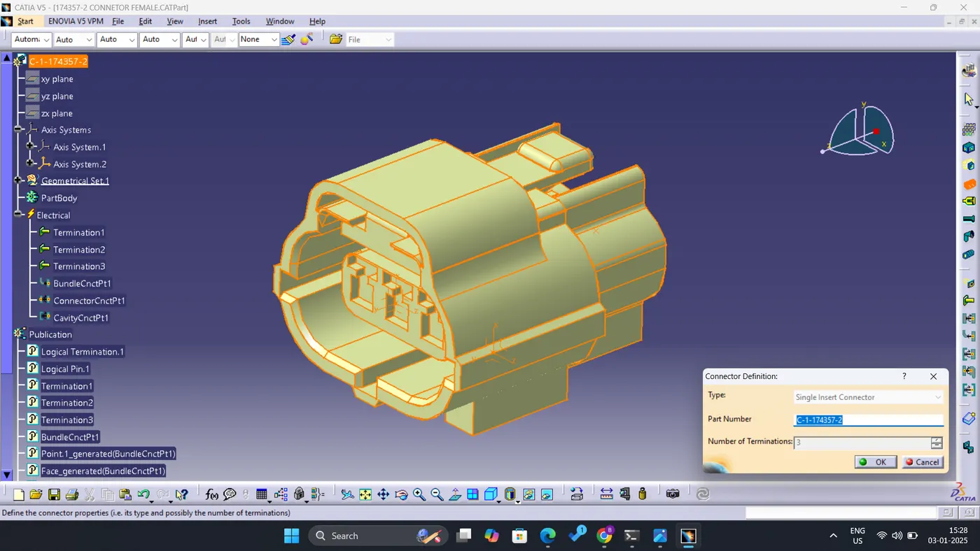
- Define the part as a connector by specifying the number of terminals, those are wire entry points.
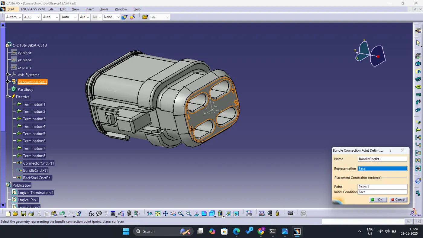
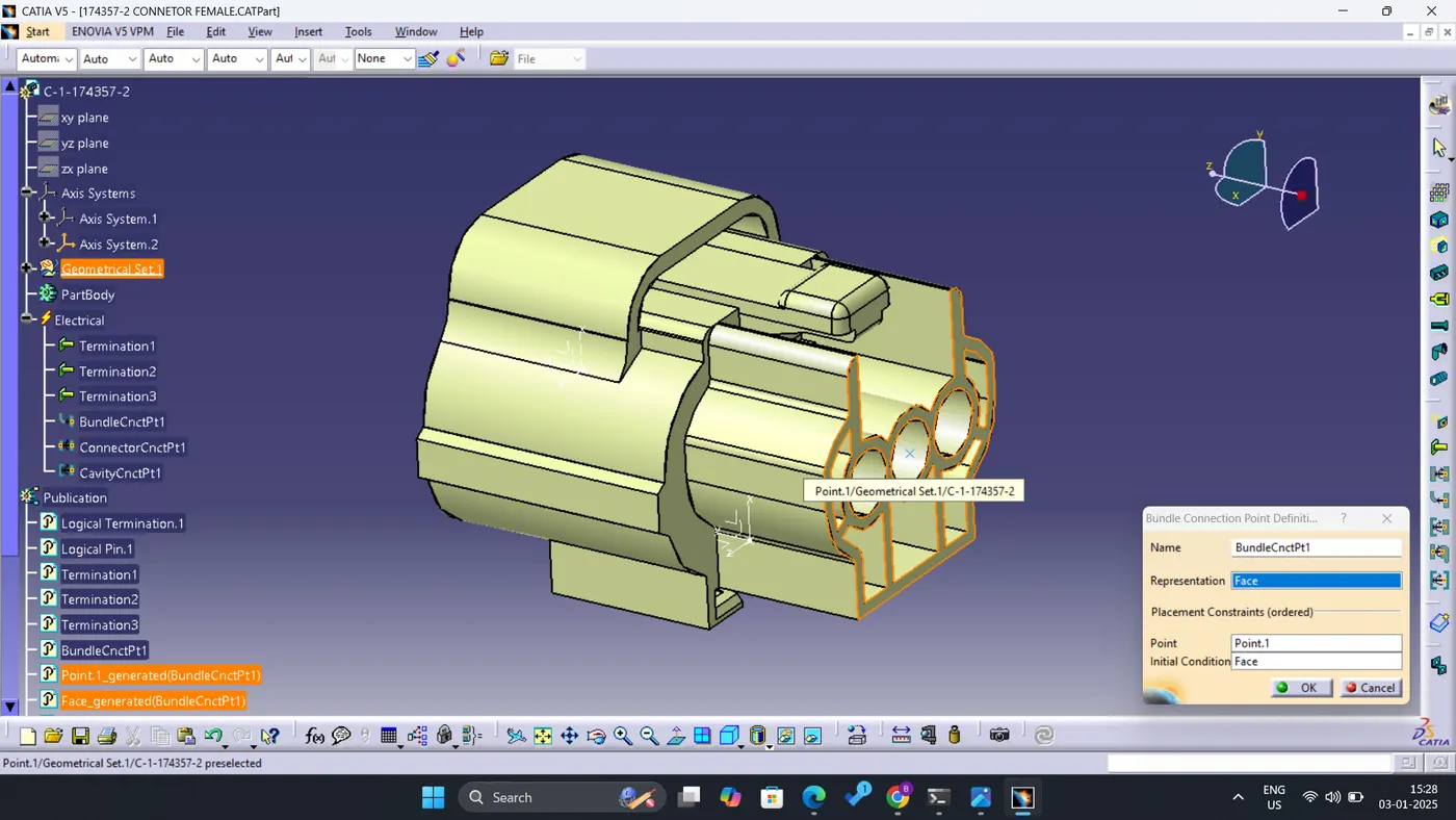
- Define Bundle Connection Point-
- select the connector
- Specify the Representation, Point, and, Initial condition
- Select OK.
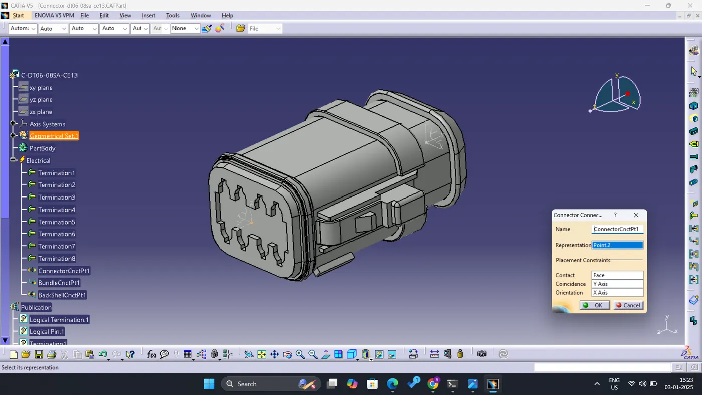
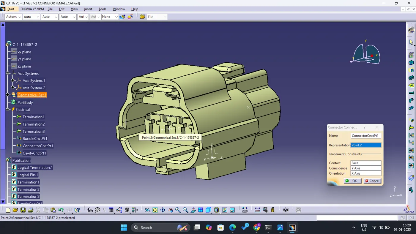
- Define the Connector connection point.
- Select the connector.
- Specify the Representation(connector connection point), Contact(connectors mating face), Coincidence (Y-axis), and, orientation (X-axis).
- Select OK.
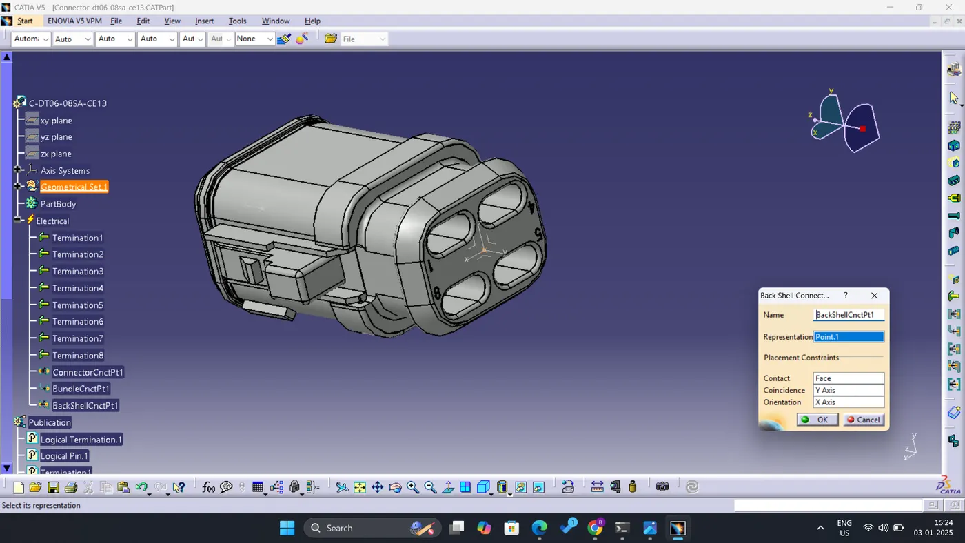
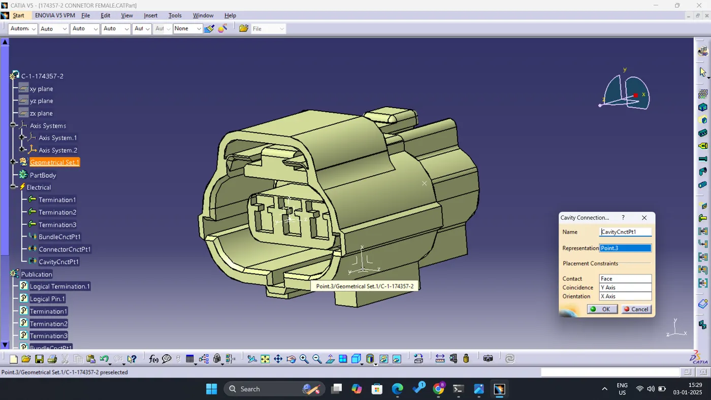
- Define cavity connection point.
- First, create the cavity connection point.
- Then add cavity connection axis system.
- Select the connector.
- Specify the Representation(connector connection point), Contact(connectors mating face), Coincidence (Y-axis), and, orientation (X-axis). The orientation of the cavity connection axis should be the same as that of the connector.
- Select OK.
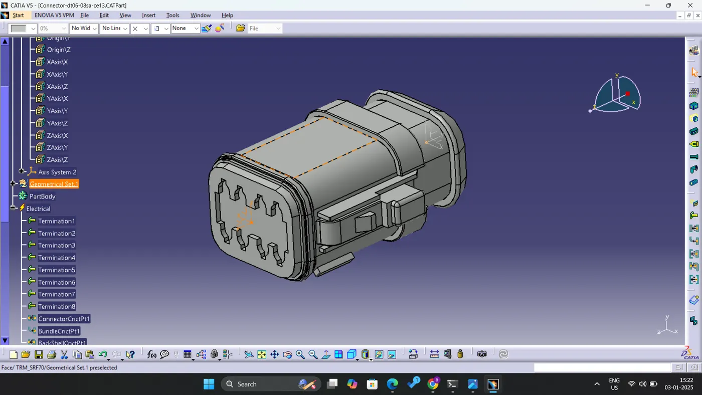
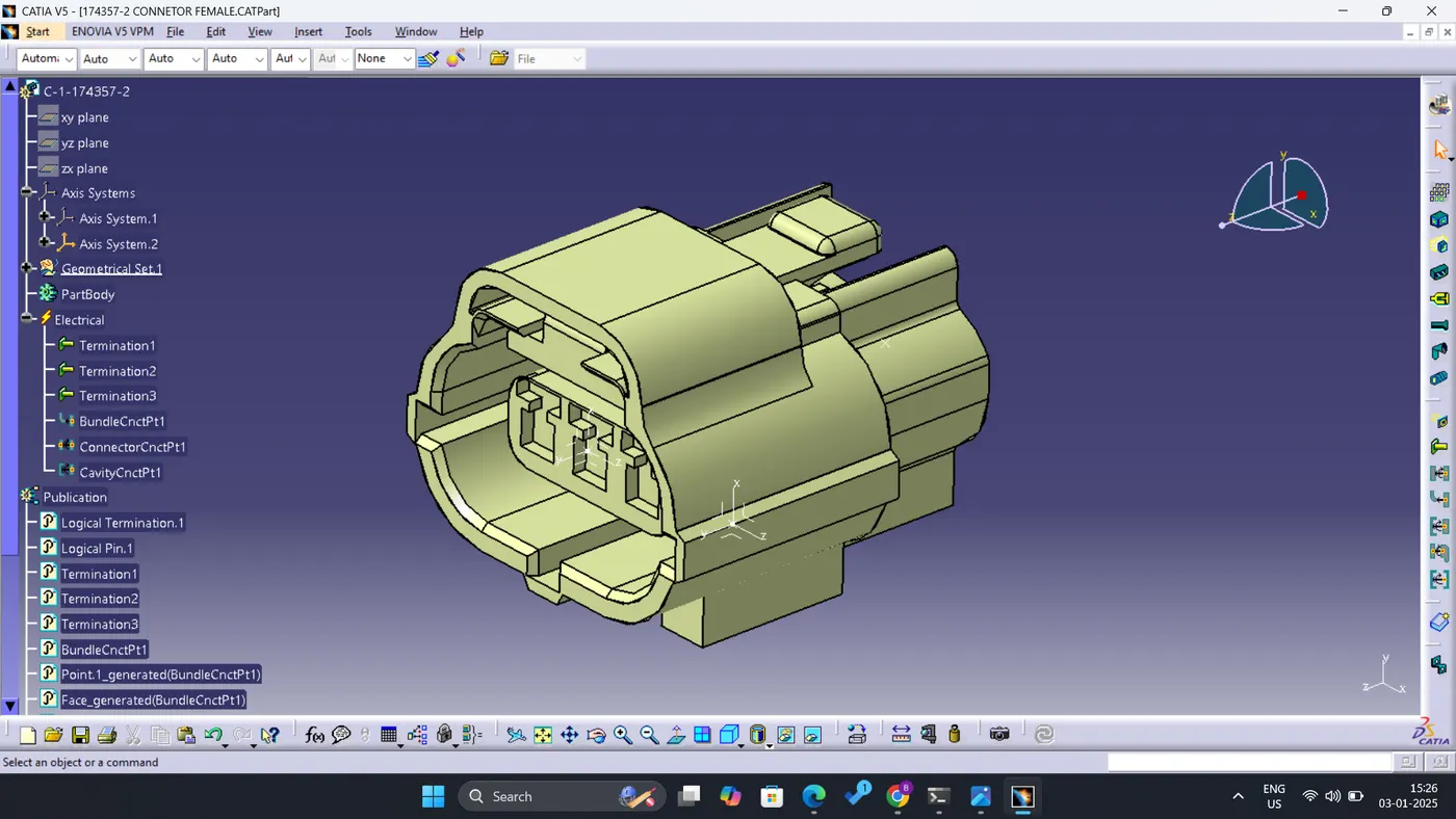
As in this challenge it is aimed to work on (1) Deutsch DT06 – 08SA (2) Tyco 174357-2 (3)Tyco 85229-1, connectors and mounting clip. Below figures shows the complete process as mentioned above.
(1) Deutsch DT06 – 08SA:
(2) Tyco 174357-2:
(3)Tyco 85229-1:
A. Assembly of Tyco 174357-2 and Tyco 85229-1:
CONCLUSION:
The specified connectors and connector clips have been effectively defined in terms of their electrical properties using the Electrical Part Design Workbench in CATIA V5, incorporating all essential attributes.