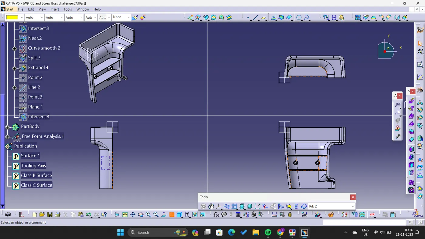
Week 10 - Challenge 1- Attachment Feature Creation (Ribs & Screw Boss)
Creation of Tooling Axis followed by Draft Analysis:
- Visualised the Class A Surface, checked the axis that will clear all edges and slots.
- Created the Tooling axis in Y-direction by taking point on the curve of the slot.
- After the tooling axis is created, to perform Draft Analysis go to Insert- Analysis- Feature Draft Analysis.
- First aligne the Compass with the Tooling Axis and lock it their.
- After that set the range of Draft as 0 to 2.5 degree with respective, it will show the results.
- Use Analyses under running point to check draft at a particular point.
- Result shows the draft of more than 2.5 degrees, highlighted in green color(Class A Surface).
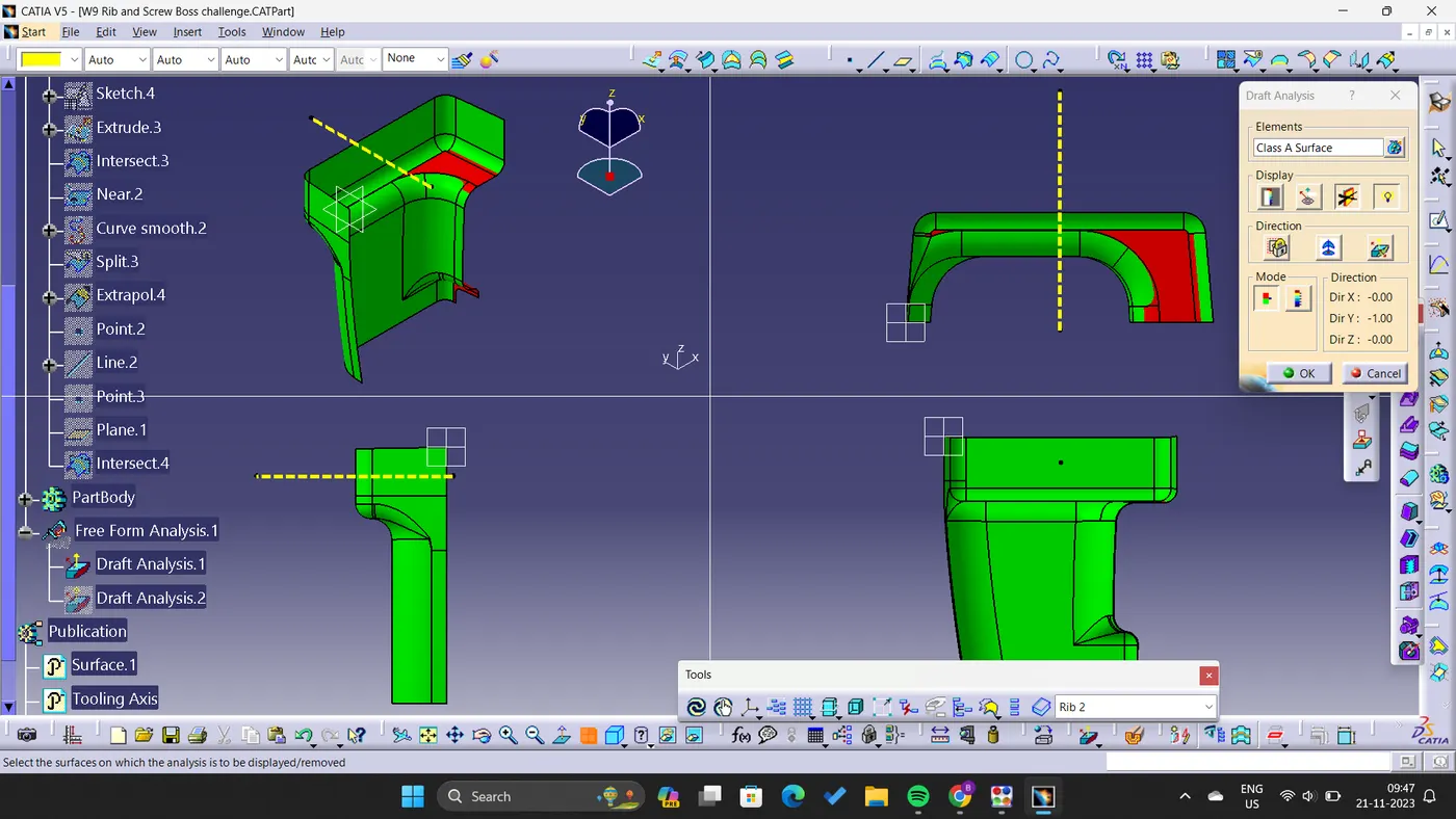
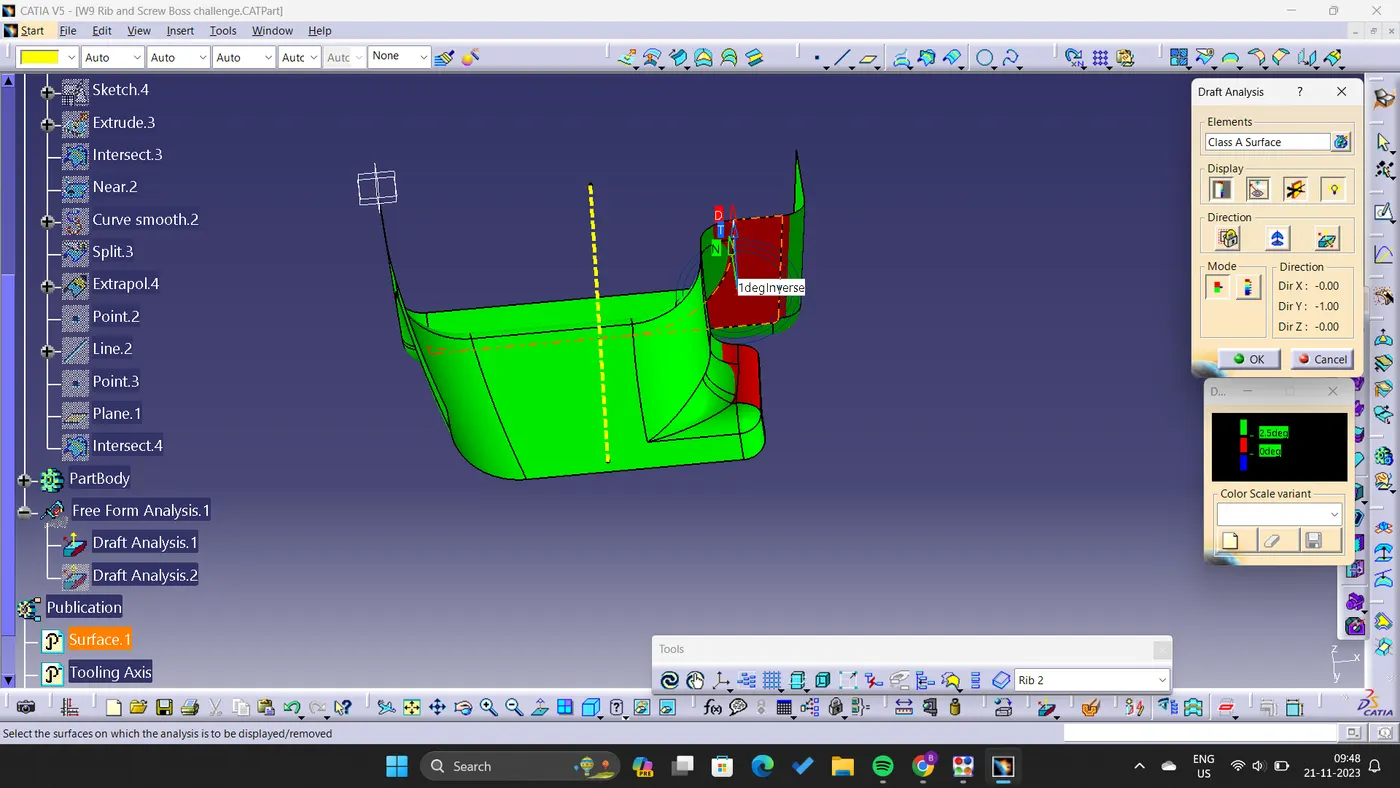
- Draft analysis of Actual Component shows the following results:
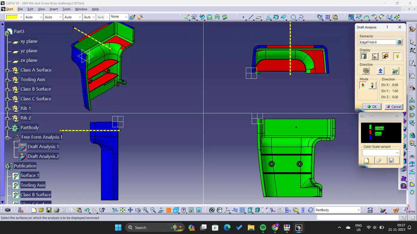
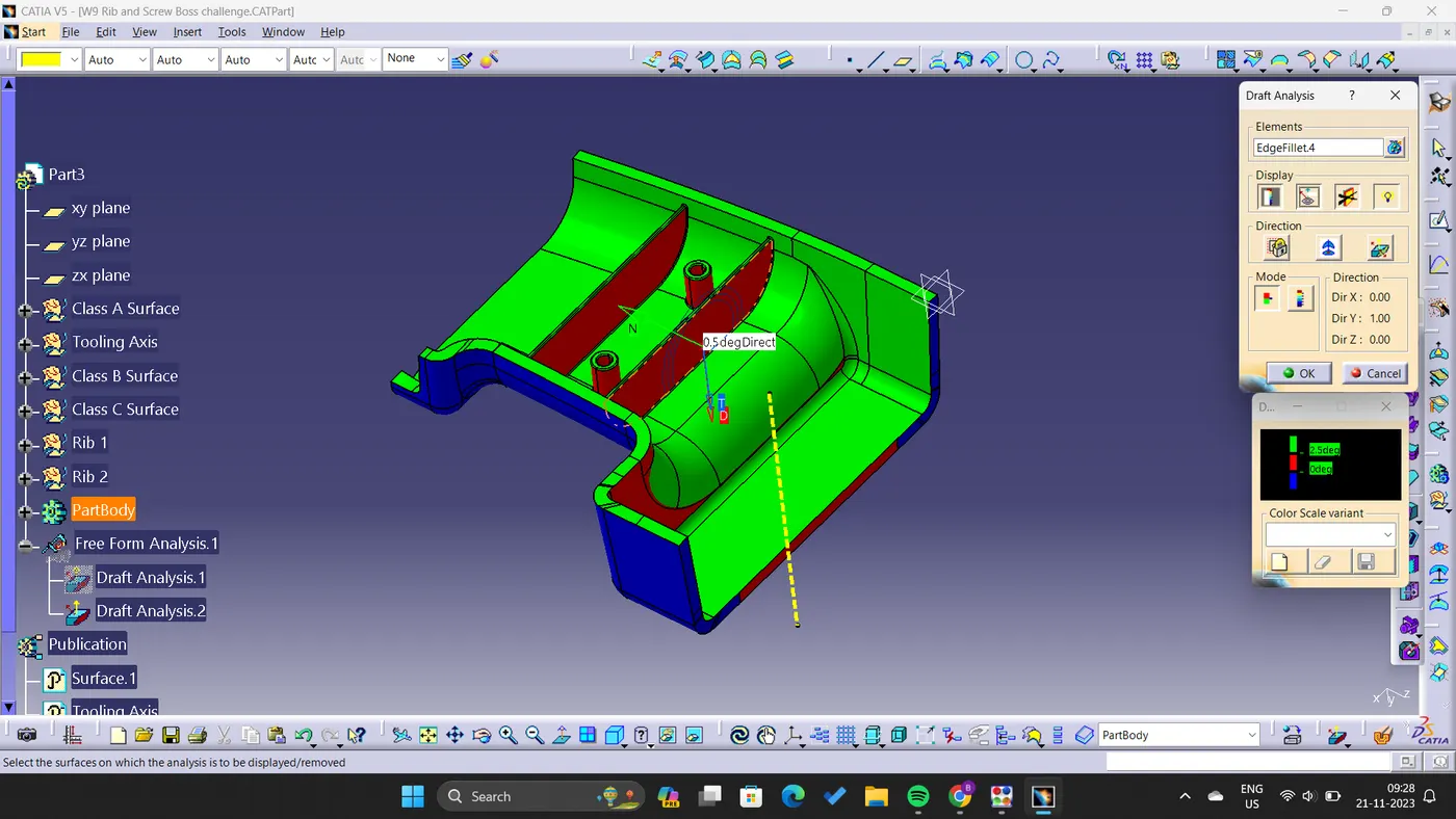
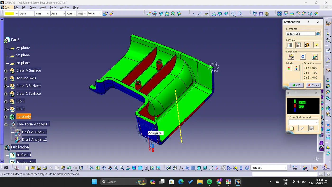
- Different Views of actual component are: