Wiring harness design in CATIA V5 - 3D modeling Week 2 Challenge
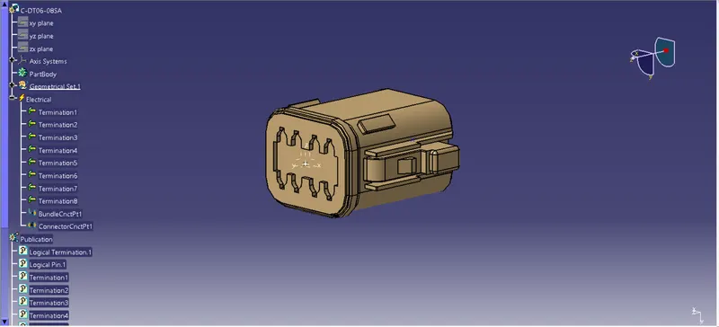
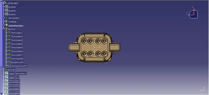
Deutsch DT06 – 08SA
Open the igs file downloaded from the product website and load the item into CATIA V5
Now open the part design workbench and insert a point at the centre of the part on mating face.
Now create an AXIS system using the point as the origin. Define the coordinates in such a way that the locking part has the X-axis and the mating direction has Y-axis.
Once the axis system is created create a point opposite to the mating face.
After the two points and axis system is created switch to the electrical part design workbench to electrically define the part.
Once we are in electrical part design workbench, on the right side we have set of toolbars. In that there's an option called "Define Connector", click on it and select the part and give the number of terminations as per the connector.
In this case the connector has 8 terminations, so number of terminaitons are 8. Now the part is electrically defined.
Now we need to define connector connection point and bundle connection point for mating purpose.
On the right hand side, in the toolbar we have option called Define connector connection point. click on it and select the face which has the axis system. The representation will be the POINT and Y-axis as the coincidence and X-axis as orientation.
In the same way, in the toolbar select the Bundle connection point and select the point as the reference and the face which is opposite the connector connection face as the mating face.
With the above explained steps we have succesfully defined the part electrically and also given the parameters that are required for the part.
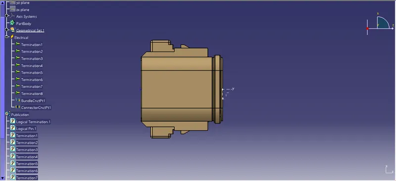
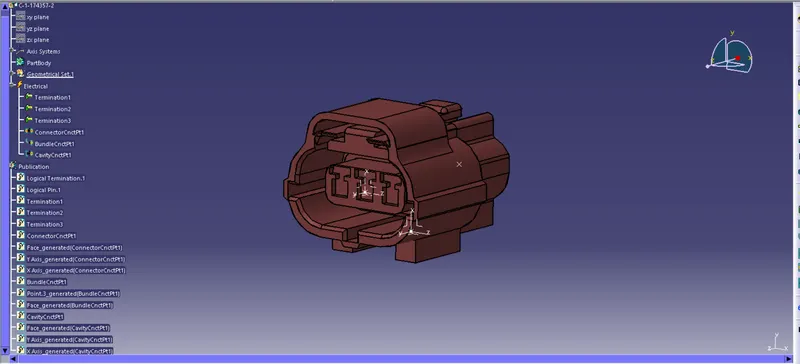
Tyco 174357-2
Open the igs file downloaded from the product website and load the item into CATIA V5
Now open the part design workbench and insert a point at the centre of the part on mating face.
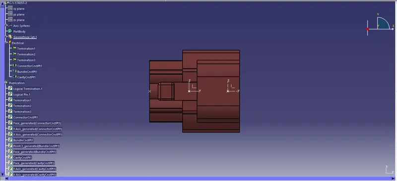
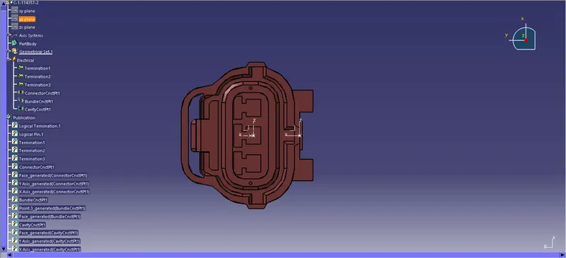
Now create an AXIS system using the point as the origin. Define the coordinates in such a way that the locking part has the X-axis and the mating direction has Y-axis.
Once the axis system is created create a point opposite to the mating face.
After the two points and axis system is created switch to the electrical part design workbench to electrically define the part.
Once we are in electrical part design workbench, on the right side we have set of toolbars. In that there's an option called "Define Connector", click on it and select the part and give the number of terminations as per the connector.
In this case the connector has 3 terminations, so number of terminaitons are 3. Now the part is electrically defined.
Now we need to define connector connection point and bundle connection point for mating purpose.
On the right hand side, in the toolbar we have option called Define connector connection point. click on it and select the face which has the axis system. The representation will be the POINT and the mating axis is Y-axis.
In the same way, in the toolbar select the Bundle connection point and select the point as the reference and the face which is opposite the connector connection face as the mating face.
For this type of connector we also have another parameter to define i.e, connector cavity point. This cavity point is defined to mate with a mounting clamp or other mounting device.
To define cavity connection point, first we need to create a point on the mounting face using part workbench. Now create an axis system using the origin as the point. Now define the Y-axis as the mating direction and the X-axis as the locking face.
Once the point and axis system are defined, now click on the Cavity connection point in electrical part design workbench. Give the point as the representation, Y-axis as the coincidence and X-axis as orientation.
With the above explained steps we have succesfully defined the part electrically and also given the parameters that are required for the part.
Tyco 85229-1
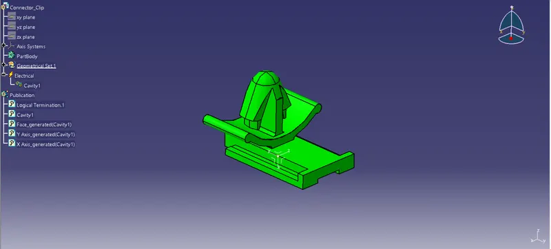
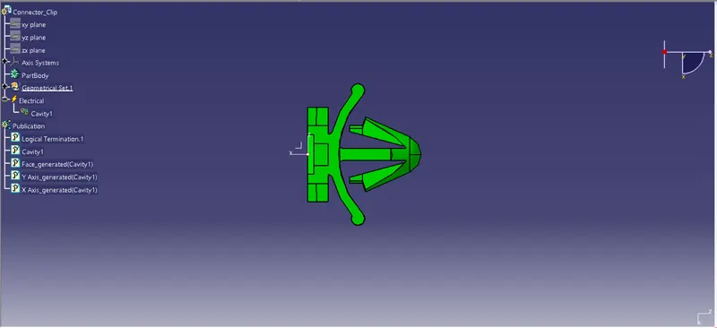
The given part is a mounting clip, so we need to define the part as mounting device.
First open the part design workbench, insert a point on the mating face. Create an axis system using the point as reference.
Define the mating direction as Y-axis and the loci]king axis as X-axis.
Click on Define cavity connection point, the reference as the point, contact as face, coincidence as Y-axis and orientation as X-axis.
In this way we have defined the clamp with electrical properties.
Creating a Catalogue:
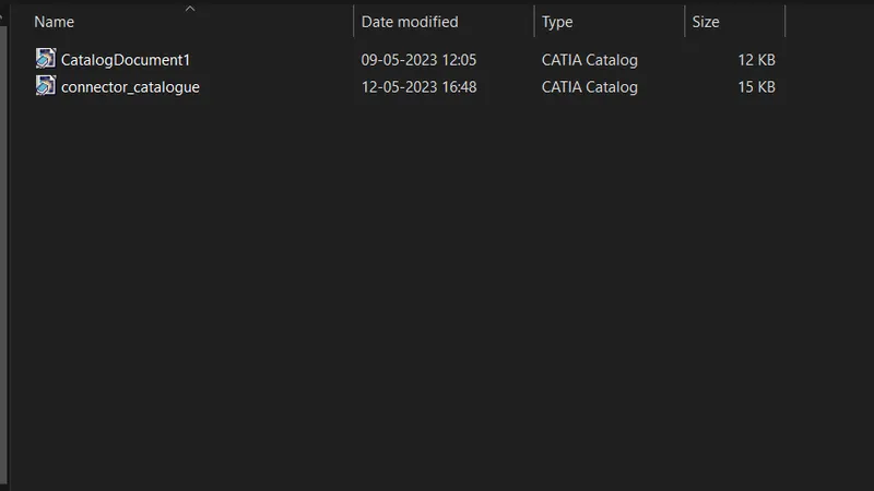
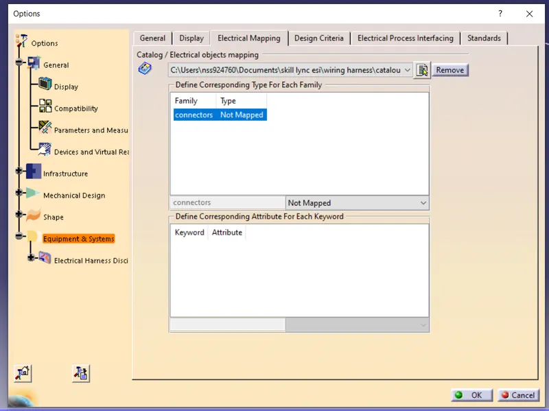
Open the CATIA V5 and select the catalogue document. Once the workbench is opened select add family. In the add family select the folder, if there is no folder create a folder for catalogue. we can select the type of catalogue. For our use we use the family as Electrical. I have created a folder called Connectors and in this the connector catalogue is saved.
Once we created the catalogue, we can add all the connectors to this single catalogue. For each electrcial part, there is an icon in the toolbar on the right hand side in the electrical part workbench. The icon name is store device. CLick on the icon and select the folder which we created for catalogue. Once we select the folder the part will be saved in that respective catalogue.