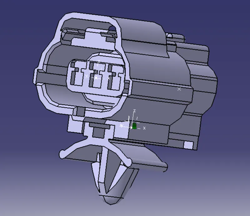
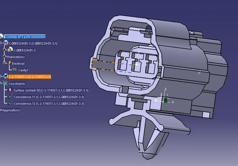
Wiring harness design in CATIA V5 - 3D modeling Week 2 Challenge
What is a conncetor?
Connector: is a device(or more precisely, a mating pair of devices, often a plug and a socket) for connecting together two or more wires, cables, or hoses, allowing electricity or fluid to flow but also allowing easy disconnection and reconnection when necessary.
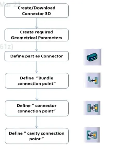
Steps to follow in electrical part design
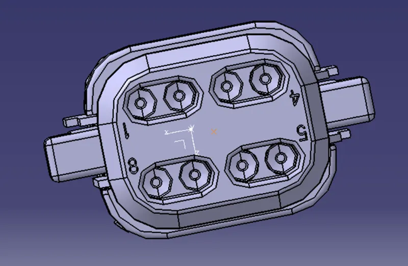
CONNECTOR 1: Deutsch DT06 - 08SA
STEP1: Import the downloaded igs file into the CATIA mechanical part workbench.
STEP2: Define bundle entry point
STEP 3: Define connector connection point
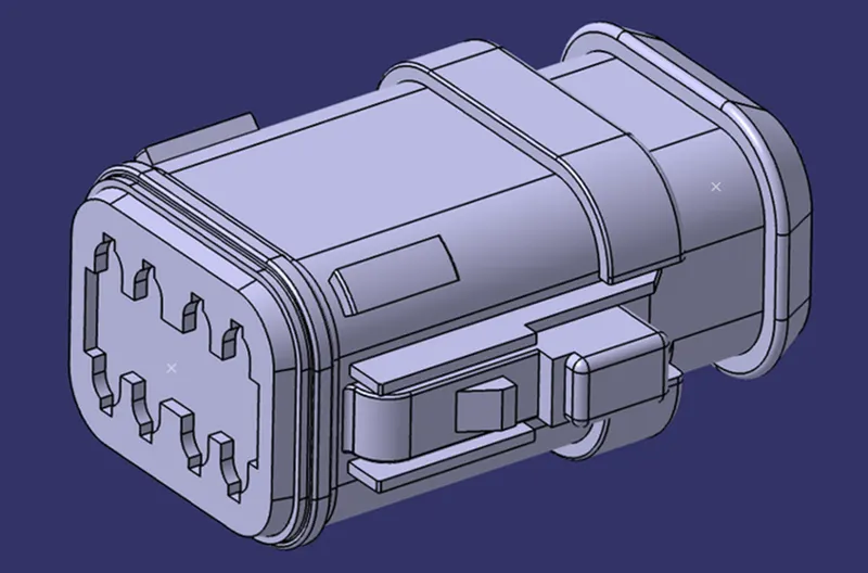
STEP 4: Define Connector Connection Axis, Such that Y-Axis should face the other mating part/direction and X-Axis should face the lock
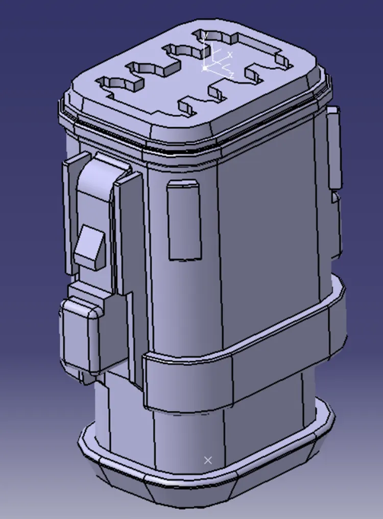
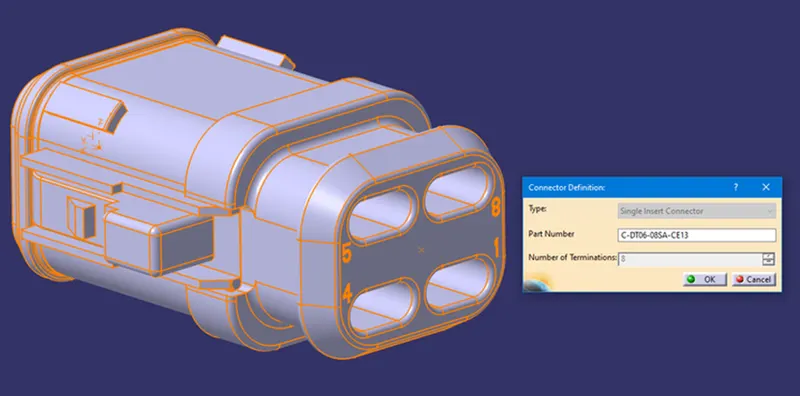
STEP 5: Now switch to the Electrical Part Design Workbench and define the connector using Define Connector Command with Name and No. of Terminals.
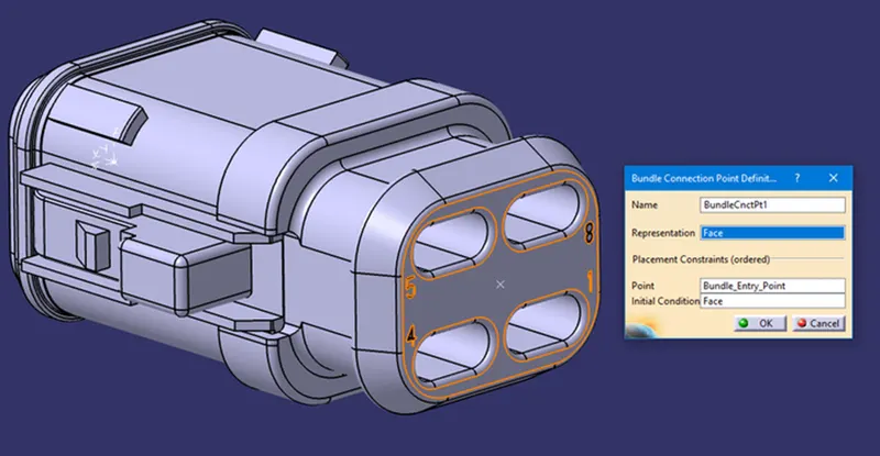
STEP 6: Define the Bundle Connection Point. Face as Representation, Bundle Entry Point as Point, and Same face as Representation for Initial Condition
STEP 7: Define the Connector Connection Point. Connector Connection Point as Representation, Mating Face as Contact, Y-axis as Coincidence, and X-Axis as Orientation.
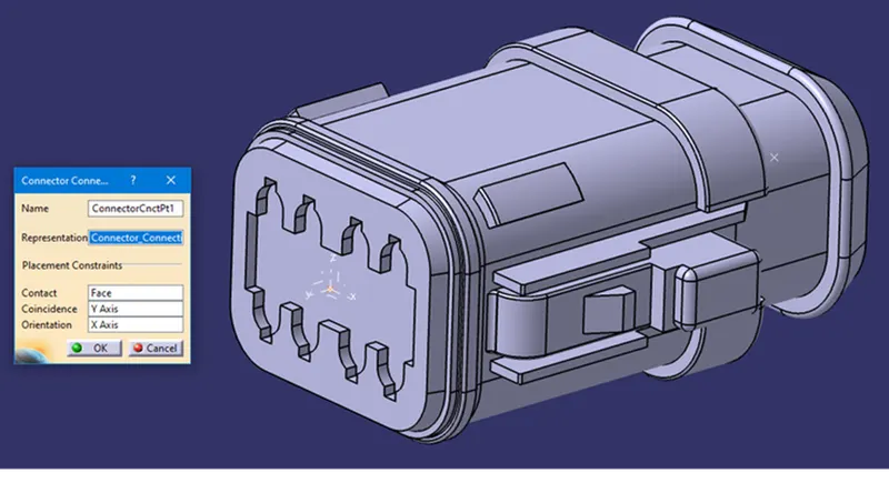
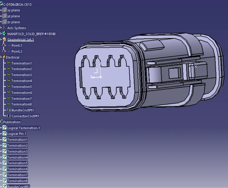
CONNECTOR 2: Tyco 174357-2
REPEAT STEPS 1 TO 4 as previously
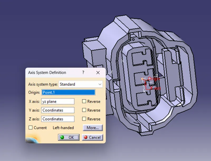
STEP 5: This connector has a Clip/Mounting Cavity. So, define the Clip/Mounting Cavity Point and Clip/Mounting Cavity Axis. Y-Axis facing mating part/direction & X-Axis facing lock.
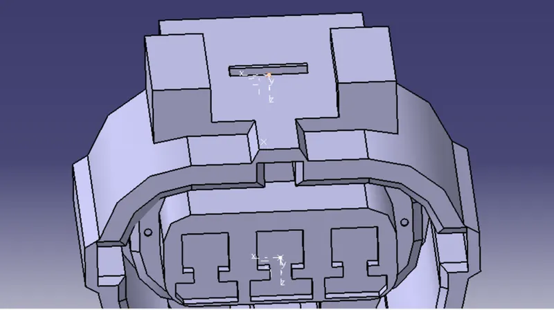
STEP 6: Now create Bundle connection and connector connection point as done for previous model
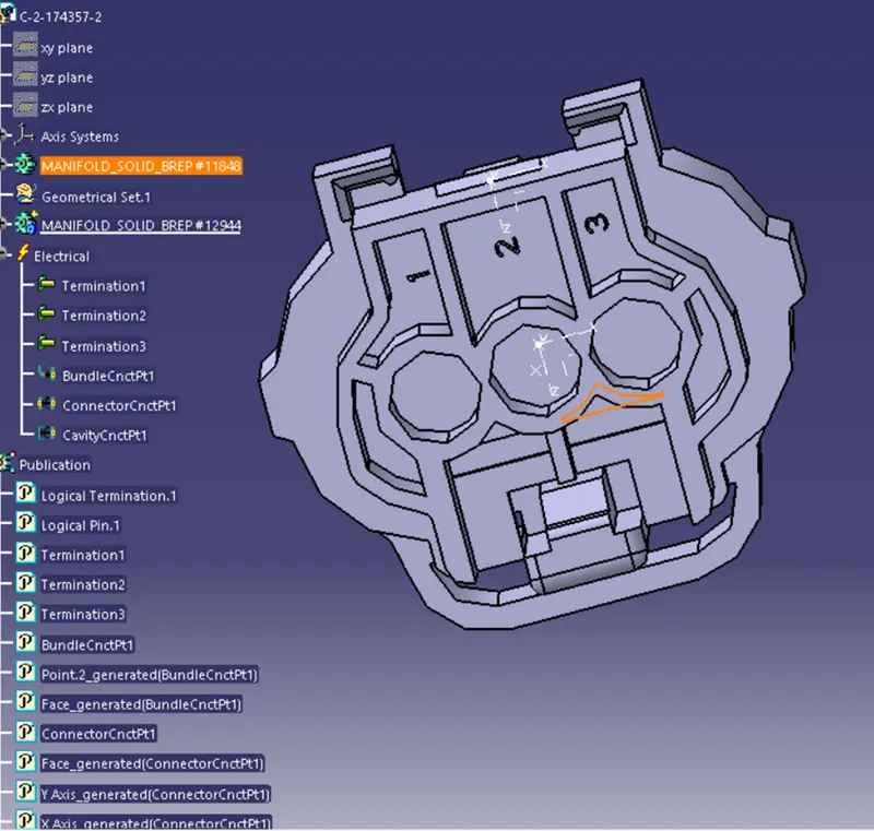
CONNECTOR CLIP: Tyco 85229-1
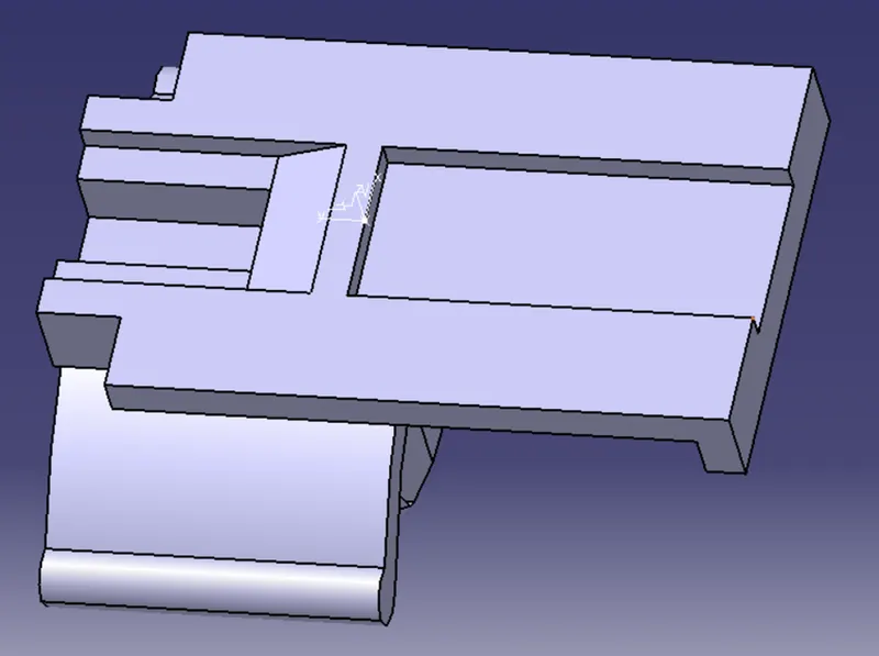
STEP 1: Import the connector clip to the CATIA mechanical part workbench
STEP 2: Define the Clip/Mounting Cavity Point and Clip/Mounting Cavity Axis Y-Axis facing mating part/direction & X-Axis facing lock. The Cavity Axis should be similar to the Connector Cavity Axis for the correct assembly of the parts.
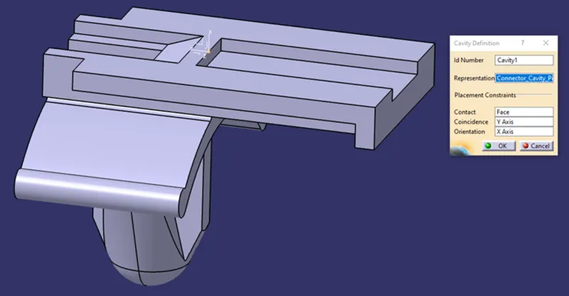
STEP 3: Define the Mounting clip as Cavity. Connector Cavity Point as Representation, Mating Face as Contact, Y-axis as Coincidence, and X-Axis as Orientation
ASSEMBLING
STEP1: Open catia product work bench and import both parts and align them properly
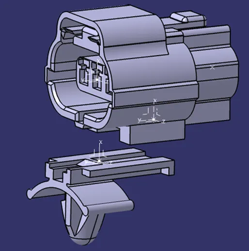
STEP 2: Using the Connect Electrical Devices command First select the Mounting Clip and then Cavity Connection Point will show on the Connector in green color automatically
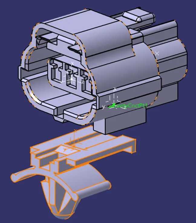
STEP 3: Select the Highlighted green point and the parts will assemble together automatically in the correct position with respect to the defined Connector Cavity Axis on both parts