Wiring harness design in CATIA V5 - 3D modeling Week 2 Challenge
Introduction on a Wire Harness
Wire harnesses bundle up different cables together using cable lacing, straps, cables ties, electrical tape, extruded string, or any of these combinations. Instead of using a single strand to bind multiple wires, wire harnesses group cables of distinct types and wraps them together with covering for robust protection against demanding environments. Each cable is wrapped individually in insulation material. Thus, one can pull out a single cable if required.
The purpose of wire harnesses is to make connectivity easier and help control power devices. They keep the systems organized by preventing cables from running all over the place. The following advantages of a wire harness assembly have contributed to its immense popularity.
Facilitate customization for specific application needs
Improve the safety of the equipment
Optimize space by grouping different wires together
Cost-effective solution for organizing multiple cables
Best suited for indoor applications
Convenient for modifying constituent cables
Important Guidelines for Cable and Wire Harness Assembly
The following are a few important steps that must be followed while assembling a wire harness.
Pre-planned Design:
It is the first and the most important step of any manufacturing process, and the same applies to wire harnesses. Depending on the individual application requirement, the manufacturer estimates how much wire would be required between each connection. A wire harness design heavily relies on what it is used for, and the material type it is subjected to during integration.
Prototyping:
This is another important step in a wire harness assembly. The wire harness prototyping allows manufacturers to get their hands on the real-time version of the final product. This helps ensure the efficient performance of the product.
Wire Cutting and Stripping:
The cables should be cut to the exact length. This is an automated process that uses cutting machines to produce wires of precise length in a bulk quantity. Once you are done with wire cutting, it is time to expose these wires by stripping the ends of the insulation material.
Assembling:
At this stage, the prepared wires along with their connectors are gathered together and constructed into the harness. This should be done manually as each wire requires to be taped off, measured, and fed through the harness to ensure that distances match the exact design specifications.
Testing:
Here, the functionality of individual wire harnesses is tested for all relevant specifications. Manufacturers carry out different types of tests such as resistance testing and continuity testing.
Vehicle electrical Distribution System(EDS) Introduction.
EDS have 4 parts
1. E&E architecture
2. Logic Schematics
3. Schematic Development
4. Wiring Harness Routing and Packaging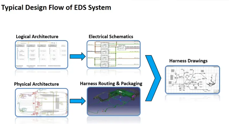
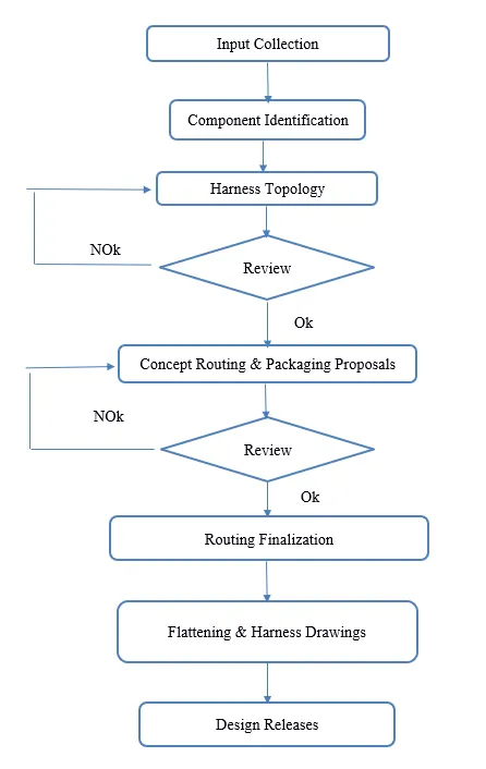
Wiring Harness Design Process
Wiring Harness Assembly Structure
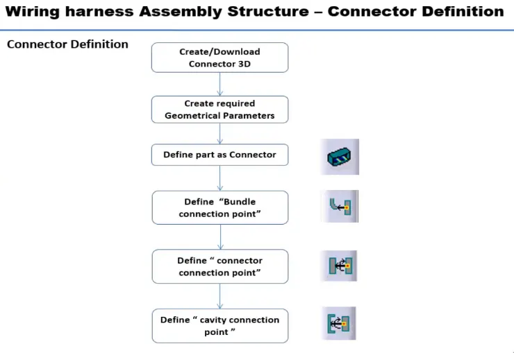
Defining a component as an electrical part:
To define the part as electrical, we follow these steps:
1. Downloading the component, or creating the component, in this case a connector.
2. Geometrical Parameters: Points and axis system needs to be created for the various connection points on the component.
3. Define Component: Then we move on to the eletrical part design workbench to define the part as electrical, without this, the connection points cannot be defined.
4. Define Bundle connection point: Defines where the harness bundle will enter from in the given point.
5. Define Connector connection point
6. Define Cavity connection point: It is optional as the connector may or may not have a clip.
WIRING HARNESS ASSEMBLY DESIGN:
- First we download the files from the above given link in the challenge.
- Then we open the 'Part Design' workbench and save the file.
- Then we use point "In bewteen" command to create a point for the connection points
- After that we create axis system from the point and define the orientation.
- Then we switch to the 'Electrical Part Design' Workbench.
- After that we define the type of equipment.
- At last we define the necessary points such as Cavity connection Point and Bundle Connection point
- Then we save the component.
1. DT06 – 08SA
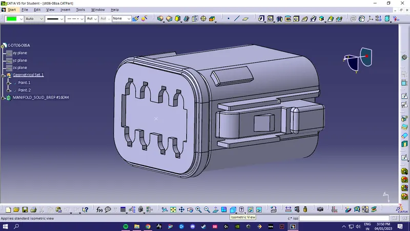
defining Axis system
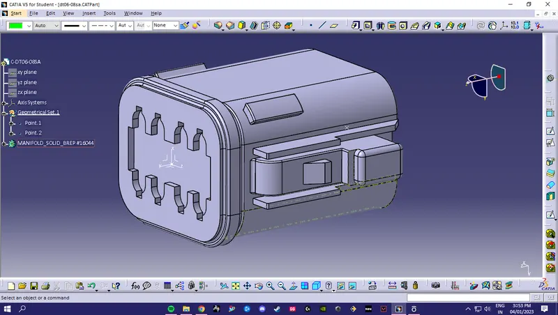
defining Connector connection point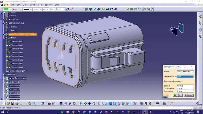
Defining Bundle Connection Point
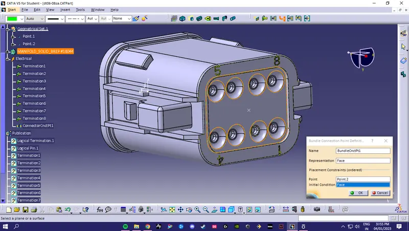
2.Tyco 174357-2 :
All the steps are the same as above part. Just here we are adding an extra point and axis sytem for the clip to be attached.
- Create midpoint
- create Connector connection point
- create Connector connection axis system
- create cavity connection point
- create cavity connection axis system
- Switch to Electric part design and define part as connector
- Define Connector connection point and cavity connection point
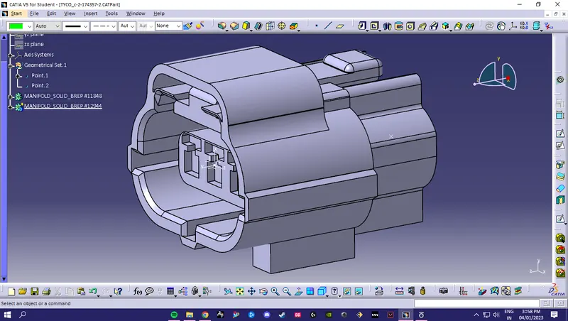
Defining axis system for connection Clip
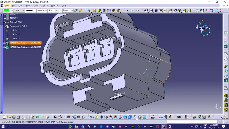
Defining Connector Connection Point
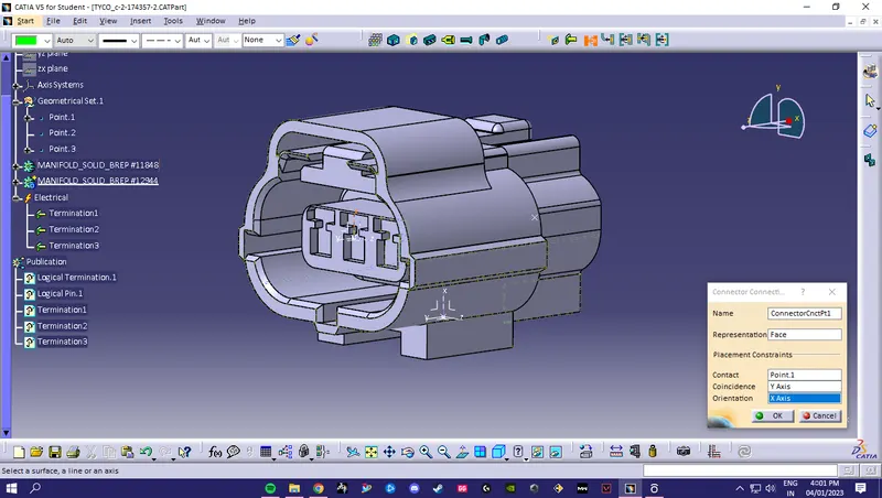
Defining Bundle Connection Point
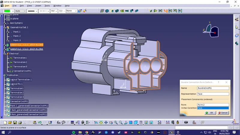
Defining Cavity Connection Point
3. Tyco 85229-1 :
For this part we have created the point and axis system where the clip will be attached to Tyco 174357-2. Also we defined the part as a Cavity so the software can recognise when we assemble the two parts.
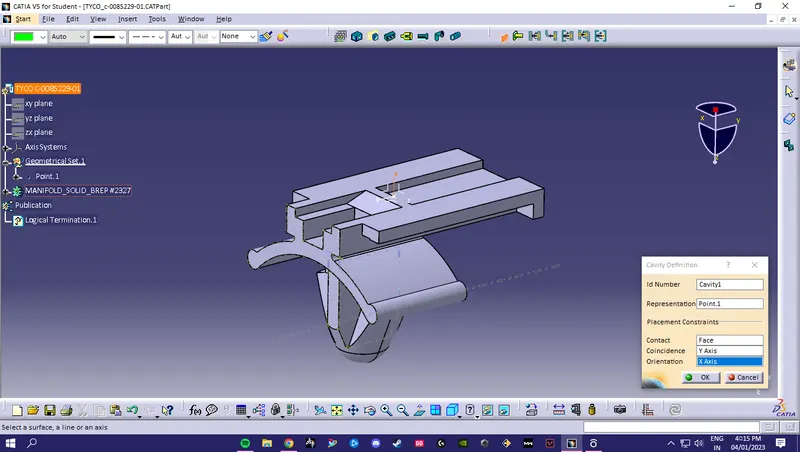
Electrical Assembly:
- We imported the Connector and cavity / mounting clip.
- Then we selected Defing Eelectric connection
- At last selected the command "connect electrical devices"
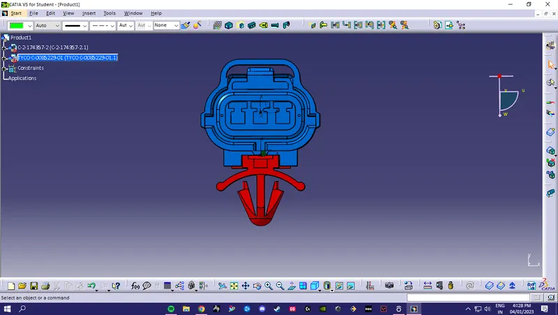
Conclusion:- Wiring harness design in CATIA V5 - 3D modeling Week 2 Challenge is completed as per guidelines
All the necessary CAD files are attached with this challenge below