Week 2- 2R Robotic Arm Challenge
Write a program in Matlab to simulate the forward kinematics of a 2R Robotic Arm
AIM: 1-Write a program in Matlab to simulate the forward kinematics of a 2R Robotic Arm
2-Create an animation file of the plot of forward kinematics of a 2R Robotic Arm.
BASIC APPROACH:-
For this I am going to have a simple approach where the basic arms of the robot linkage known as Forward kinematics of a 2R Robotic arm (where 2R means 2-rotating Link i.e 2 is a number of link and R is rotation). I am taking two links as a representative of the Robotic arm in which Link-1 is Hinged at (X0, Y0) and making an angle theta1, while Link-2 is hinged at the end of the Link-1 and making angle theta2 with respect to the Datum.
There are 2 steps required for this program,
- Step-1: Calculating the position of Link-1.
- Step-2: Calculating the position of the Link-2.
Detailed Procedure and Explanation:-
- Step-1: Calculating the position of Link-1.
From the fixed Support, the initial value of X and Y for the Link-1 (X0, Y0) and the final value is (X1, Y1)
`X0=0` [this is to get the xaxis value of link 1 at the hinged point of link 1]
`Y0=0`. [this is to get the yaxis value of link 1 at the hinged point of link 1]
`X1= l1* cosd(theta_1)` [this is to get the xaxis value of link 2 at the end point of link 1]
`Y1 =l1* sind(theta_1)` [this is to get the yaxis value of link 2 at the end point of link 1]
- Step-2: Calculating the position of the Link-2.
For the Link-2 starting point is the Ending point if the Link-1 i.e (X1, Y1) and Ending point is (X2, Y2).
`X2 = X1+l2* cosd(theta_2)`. [this is to get the xaxis value of link 2 at the end point of link 2]
`Y2 = Y1+l2* sind(theta_2)` [this is to get the yaxis value of link 2 at the end point of link 2]
Writing Basic Program.
Now this is a program with the 2D plot without the animation.
for this plot the values of l1,l2,`theta_1`,`theta_2` are given below;
l1=1
l2=0.5
`theta_1=45`
`theta_2=30`
This is the program used:
%forward kinematics of a 2R robotic arm manupulation
clear all
close all
clc
%inputs
l1=1 %length of the linkage 1 from hinged point
l2=0.5 %length of the linkage 2 from the end point of linkage 1
theta1=45 %angle made by link 1 with respect to hinged point
theta2=30 %angle made by link 2 with respect to the Datum.
%co-ordinates
x0=0 %starting co-ordinates from hinge point or starting point(xaxis)
y0=0 %starting co-ordinates from hinge point or starting point(yaxis)
x1=l1*cosd(theta1); %end co-ordinates of linkage 1(xaxis)
y1=l1*sind(theta1); %end co-ordinates of linkage 1(yaxis)

x2=x1+l2*cosd(theta2); %end co-ordinates of linkage 2(xaxis)
y2=y1+l2*sind(theta2); %end co-ordinates of linkage 2(yaxis)
%plotting
line([x0 x1],[y0 y1],'linewidth',3,'color','b')
line([x1 x2],[y1 y2],'linewidth',3,'color','r')
grid on
OUTPUT:
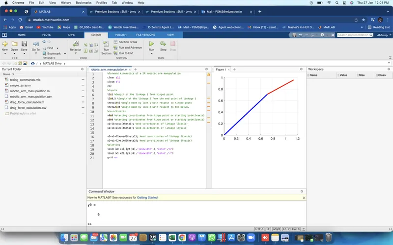
This is the required 2D plot we get after executing the program.
The link 1 of the robotic arm is in color blue and te link 2 of that arm is in color red.
But in this, we are not getting the animated plot; for that we are using a separate program in the next step.
NOTE: AS I HAVE FACED NO ERRORS SO NEITHER ERROR CORRECTION NOR ERROR SCRENSHHOTS HAVE BEEN ATTACHED
2-Create an animation file of the plot of forward kinematics of a 2R Robotic Arm.
Step-4: Program for Arm Animation and Error Elimination.
Here we are taking multiple angles and multiple values of (X, Y).
For that we are going to take the help of linspace command which is as follows,
theta1=linspace(0,90,10)
theta2=linspace(0,90,10)
Where:-
In linspace command the first value represents the starting point of angle, similarly, the second point represents the ending point of the angle and at last, the third point represents the number of values between them.
We are using linspace command to have multiple values of both the angles so that we can create a plot and an animation of how the robotic arm will move corresponding to the values of `theta_1` and `theta_2`
To change the angles we are using For-loop command as shown below:
for i=1:length(theta1)
    THETA1=theta1(i);
    THETA2=theta2(i);
HERE the value of (i) changes as we are taking the values of angle1, angle2 from the original arrays, and assigning to the variable called THETA1, THETA2.
We use the value of (i) to take particular value for theta_1 and theta_2 and then we are going to perform forward kinematics calculation hence, rearranging Program in the following manners:
for each value of theta_1 , each position of the link1 and link2 can take multiple positions; which depends on theta_2.
Also, if it is THETA1 then THETA2 requires another for-loop as for each value of theta_1, we are looping the value of theta_2, which is as follows.
for i=1:length(theta1)
    THETA1=theta1(i);
    for j=1:length(theta2)
        THETA2=theta2(j);
As for the kinematics calculation we are copying that from the fisrt progam below the line
 x0=0;
        y0=0;
        x1=l1*cosd(THETA1);
        y1=l1*sind(THETA1);
        x2=x1+l1*cosd(THETA2);
        y2=y1+l2*sind(THETA2);
for plotiing we use the same
  %plotting
        line([x0 x1],[y0 y1],'linewidth',3,'color','b')
line([x1 x2],[y1 y2],'linewidth',3,'color','r')
    end
end
And this is the pot we are getting but without animation:
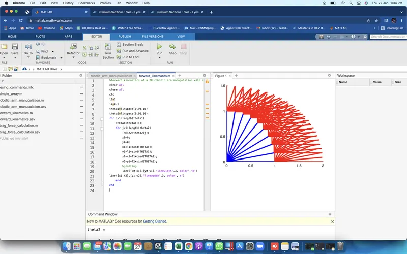
To eliminate this we are typing figure(ct) before plotting and outside for-loop ct=1
And after the plot command type ct=ct+1 (i.e we incrementing the value each time program gets executed in the for-loop) and executing the command we get 100 independent plots (because our angle1 value is 10 and angle2 value is also 10).
Therefore to get rid of this we are using plot command instead of line command.
line([x0 x1],[y0 y1])
line([x1 x2],[y1 y2])
Again we get the same result but most recent link as a plot result. To prevent this we are using hold on and pause command.
Now we are going to remove the 2nd plot command and make the first plot as below
plot([x0 x1],[y0 y1],[x1 x2],[y1 y2])
 hold on;
          plot([x0 x1],[y0 y1],[x1 x2],[y1 y2],'linewidth',3)
          pause(0.3)
          ct=ct+1;
we get an animated plot with random color changes as shown below
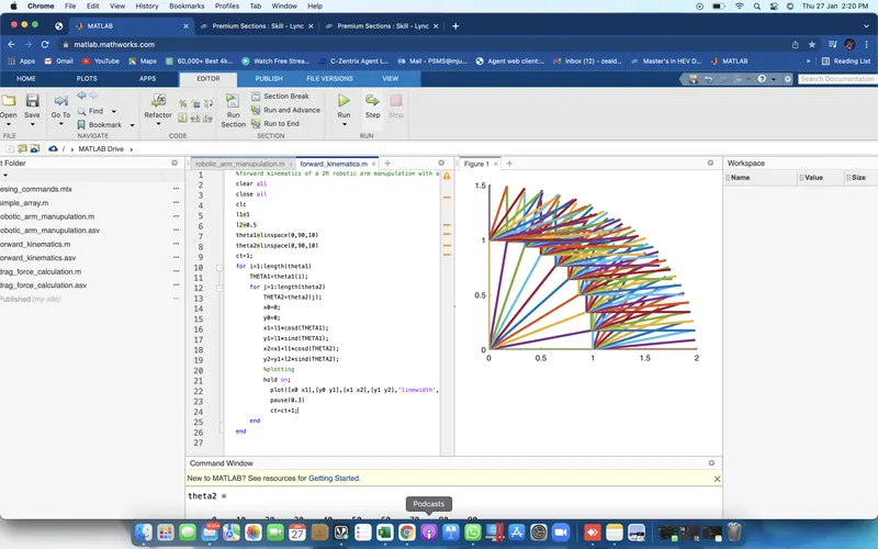
Now removing hold on command and including the axis command, adjusting the pause interval is gives us the better result.
an axis of ( -0.1 1.5 0 1.5) gives us a better result.
Step-5: Creating a movie.
To create movie we used this command M(ct)=getframe(gcf) just below the pause(0.3).
Where:- ct represents every frame and getframe command represents to getting the current figure in the gcf window. Further, we are going to save all the figures in the array called (M).
Further, we are creating avi file to get this we are using following commands.
videofile = VideoWriter(‘forward_kinematics.avi’);
open(videofile)
writeVideo(videofile, M)
close(videofile)
This is the final program for animation:
%forward kinematics of a 2R robotic arm manupulation with animation
clear all
close all
clc
l1=1
l2=0.5
theta1=linspace(0,90,10)
theta2=linspace(0,90,10)
ct=1;
for i=1:length(theta1)
    THETA1=theta1(i);
    for j=1:length(theta2)
        THETA2=theta2(j);
        x0=0;
        y0=0;
        x1 = l1*cosd(THETA1);
        y1 = l1*sind(THETA1);
        x2 = x1+l2*cosd(THETA2);
        y2 = y1+l2*sind(THETA2);
        %plotting
        plot([x0 x1],[y0 y1],[x1 x2],[y1 y2],'linewidth',3)
        axis([-0.1 1.5 0 1.5])
        pause(0.3)
        M(ct)=getframe(gcf);
        ct=ct+1;
    end
end

movie(M)
videofile = VideoWriter('forward_kinematics.avi','Uncompressed AVI');
open(videofile)
writeVideo(videofile, M)
close(videofile)
NOTE: AS I HAVE FACED NO ERRORS SO NEITHER ERROR CORRECTION NOR ERROR SCRENSHHOTS HAVE BEEN ATTACHED
Conclusion:
Hence, We are able to Program the 2R robotic Arm, with the help of this program.