Wiring harness design in CATIA V5 - 3D modeling Week 2 Challenge
INTRODUCTION
Wiring harness is the combination of electrical and mechanical CAD to connect all the electrical parts in the automotive at the optimum level.
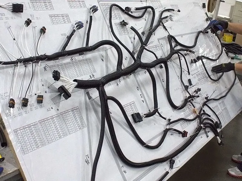
DESIGN OF WIRING HARNESS IN CATIA V5
To design the wiring harness in CATIA V5, the interface and some settings have to be changed in the design modeler.
The electrical part design, electrical harness assembly, electrical harness installation, electrical harness flattening, and electrical assembly design have to be customized to the workbench for easy access.
1) Electrical part design: The mechanical part is converted into an electrical part by manipulating the electrical properties into it.
2) Electrical Harness Installation: Route the harness.
3) Electrical Harness Flattening: Finalizing the routing.
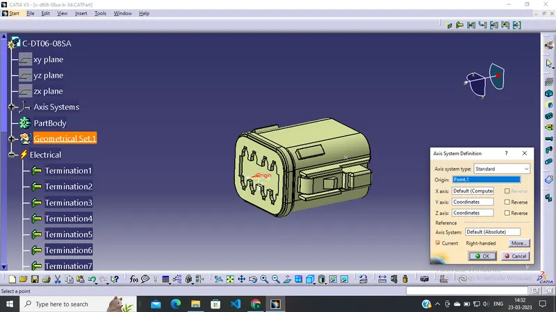
1.Deutsch DT06 – 08SA:
- Create midpoint on the contact face which will be normal to wire bundle insertion. When the creation bundle connection point includes number terminals, it would reflect in the tree structure.
- After bundle connection point, we would start connector connection point. Create a point in the mid face and create an axis X axis should be orientation, Y axis should be mating point, Z axis should be Left and Right position.
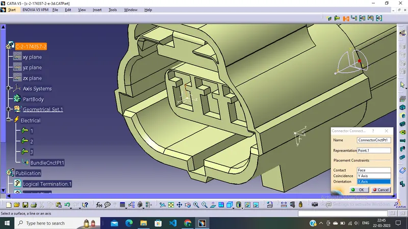
- Tyco 174357-2 :
- Create midpoint
- create Connector connection point
- create Connector connection axis system
- create cavity connection point
- create cavity connection axis system
- Switch to Electric part design and define part as connector
- Define Connector connection point and cavity connection point.
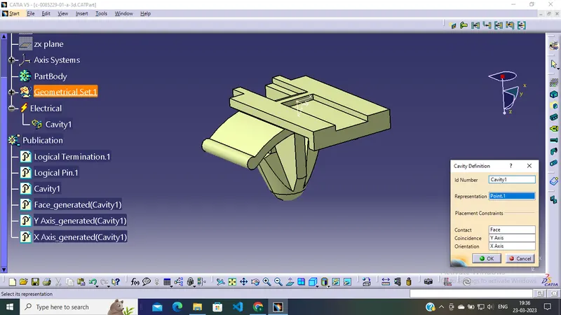
- Tyco 85229-1 :
- Create midpoint
- create cavity connection point
- create cavity connection axis system and orientation should be same as in connector
- Switch to Electric part design and define part as Mounting Equipment
- Define cavity connection point.
Elctric Assembly Design
- Import Connector and cavity / mounting clip into the new product sheet.
- Switch into the electrical Assembly design.
- Define the connecting link and select cavity and then connector.
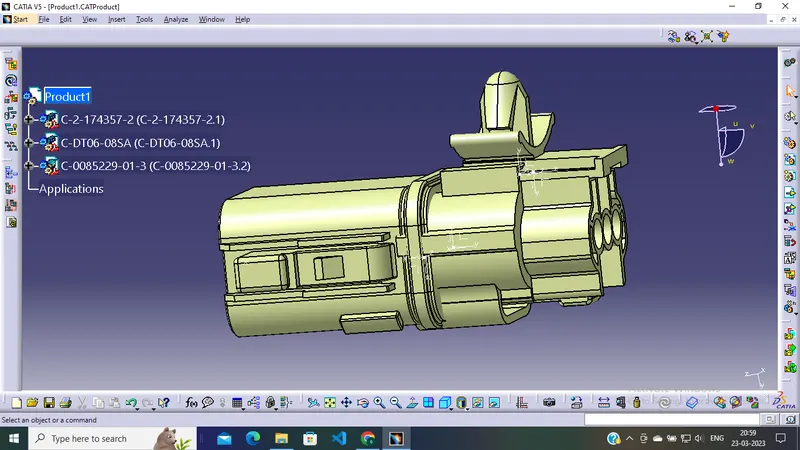
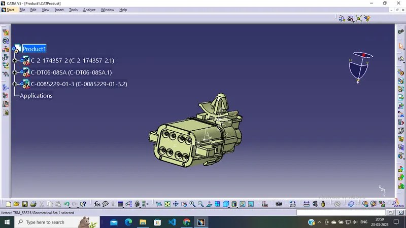
CONCLUSION:
The connector is successfully modeled in CATIA V5 and the same is added to the catalog for further references.