Week 8 - Challenge 1 - Base Bracket Design
Aim :
To Create the Base Bracket Plastic component through the given Class-A surface. To begin with, the tooling axis for the given Class-A Surface should be created meeting the requirements of the draft angle and at the end perform the Draft analysis on the model.
OBJECTIVE:
- To create a Tooling axis for a class 'A' Surface, which meeting the requirement of the draft angle and to analyse the solid model.
- To create a the surface B and C Surface
- To create a report which explains the Draft analysis and Tooling Axis cration and colour scale varients.
- To attach the screenshots of the 3D Part Model in different orientations.
Tooling Axis:
The Dummy tooling axis is created to creat the main tooling axis.Take the intersection of the bracket body and make the lines in the deficult area in the bracket.Then Bisect the lines to create the tooling axis.
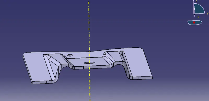
Class-B surface:
Class -B surface is created by extracting each wall and untrimming and extrapolating the walls to obtain the shape by trimming the excess surfaces and offsetting it to a certain distance based on the thickness of the model.The offset surface will be the B-surface.
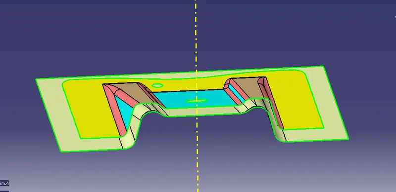
Class-C surface:
The surface created using sweep command by sweeping the boundaries of A-surface along the tooling axis to connect from A to B-surface is known as C-surface.
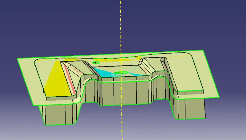
CLosed Surface:
By using the Join feature the Class A and Class C Surface are Joined Together wit the Merging Distance of 0.001 mm. For Joining with the Class C Surface both the created Holes are been selected and Joined Together.The Final Trimming Has been performed on the Class B and Joined Class A and C surfaces. Te Trimming as been performed.
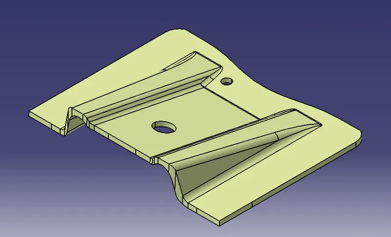
Draft Analysis:
The Draft analysis is performed based on colour ranges identifying zones on the analyzed element where the deviation from the draft direction at any point, corresponds to specified values. Here I am taking the draft angle 0 to 3 degree. Value obtained less than 3 will be highlighted in red, These regions Drafting is not possible .Hence Tooling axis should be changed or additional process is to done to produce the part.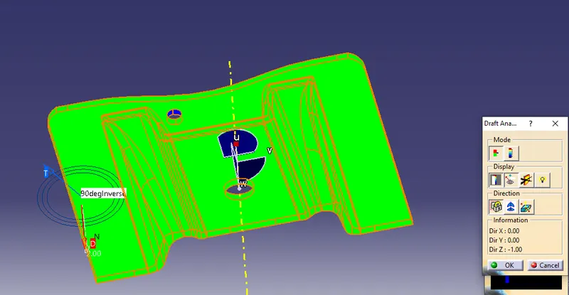
In the Display window the clour code varients are been selected, to know the range of the draft in the Class A surface. In the Display Window the colour varient shows,
- For 3 degeree - Green Colour Varient (Positive)
- For 0 degeree - Red colour varient.
- For Negative degeree- Blue colour Varient.
The drafting are been performed in both the core and cavity side of Class A Surface. The Green colour Implies the draft angle are in the positive region. if The draft angle are been inverted the colour of the surface are imled as Blue colour.
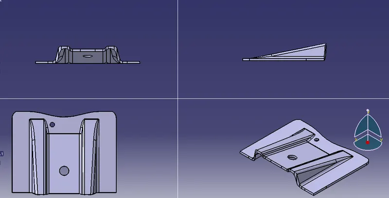
3 DIMENSION PART AND ORIENTATIONS:
- Front View
- Side View
- Top View
- Isometric View
Conclusion:
- The Base Bracket Plastic Part Component using the Class 'A' surface are Created.
- The Tooling axis for a class 'A' Surface, which meeting the requirement of the draft angle are analysed and perfrmed.
- The solid model from the surface are created by using the Closed Surface Feature.
- The detailed report which explains the Draft analysis and Tooling Axis cration are explained.
- The 3D part Model with various orientations are attached.