Wiring harness design in CATIA V5 - 3D modeling Week 2 Challenge
Report on giving the elecrical defination to the connectors and clip and creation of catalog document containing these components.
Aim: To give the electrical defination to the given clip and connectors in electrical part design after giving the geometrical parameters and then creation of catalog document of them
Given Connectors and clip:
- Deutsch DT06 – 08SA ( https://www.te.com/usa-en/product-DT06-08SA.html)
- Tyco 174357-2 (https://www.te.com/usa-en/product-2-174357-2.html?source=header-match)
- Tyco 85229-1 – (https://www.te.com/usa-en/product-85229-1.html?q=85229&source=header)
Step 1: Download all necessary given connectors and clip from te.com, unzip the igs file and start working on them one by one on CATIA V5
- First we will work on DT06 – 08SA connector, by opening the file in part design and start giving the geometrical parameters to it, gometrical parameters include creation of bundle connection point, connector connection point and axis system to it.
- So for bundle connection point we create a mid point on surface where terminal bundles is going to attach, so we create the mid point on that surface.
- for cavity connection point we give a mid point on the mating side of connector and define it as connector connection point.
- Now give axis system by taking the connector connection point as origin and direction of Y axis should be along the mating direction, Direction of X axis should be along the locking system of connector and Direction of Z axis should be left - right oreintaion of connector.
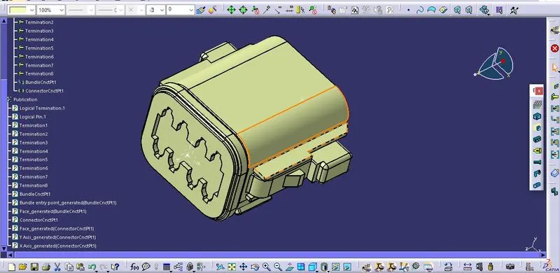
- Now define the connector by command on electrical part design and give no. of termination as 8 because there are 8 bundles segment.
- Now define the bundle connection point by giving the face of point as referance and point as bundle entry point and initial condition as face normal to point.
- Now define the connector connection point, by taking the representation as point face at which terminals of other connector is going to meet, coinidence as Y axis and oreintation as x Axis.
- So our electrical defined connector will look like this:
Step 2: Now open the another connector igs file naming Tyco 174357-2, then open the file in the part design to give geometrical parameters same as we did in previous connector.
- In similar way as we did with previous connector we create the bundle connection point, connector connection point and axis system to connector connection point, such that the Y axis of axis system is along the mating direction, X axis along the locking surface and Z axis along the left-right orientation.
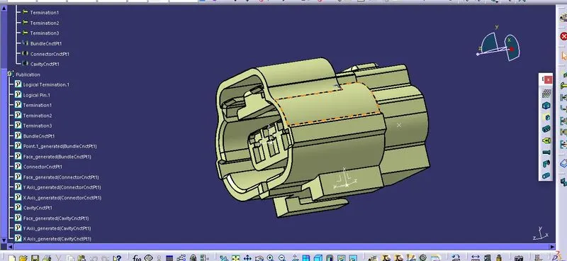
- Also give cavity connector point because we this connector has slot to attach the clip, so we define the mid point of edge where clip going to attach as the cavity connector point, then define the axis system and taking this point as representation ,face as the contact face where the clip is going to attach, coincidence along the Y axis and oreintation along the X axis.
- Now define the connector with its 3 terminals and define bundle point and connector connection point same as we did in previous connector.
- Now define the cavity connector point in same way we defined the connector connection point.
- so our final electrically defined connector will look like this:
Step 3: Now start working on the clip igs file name Tyco 85229-1, open this file in part design to give geometrical parameters to it.
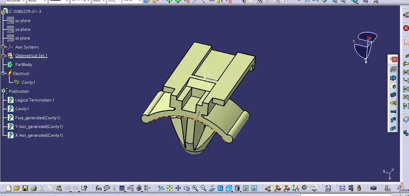
- In geometrical parmeters we define cavity connector point on the sharp edge where the clip is going to mount to the connector, then give axis system to this connector point taking it as origin and defining Y axis in the mating direction, X axis in the locking direction and Z axis in the left-right orientation of connector.
- Now define this point electrically by taking the point as representation point, contact face where the clip going to contact with the connector, coincidence as Y axis and oreintation as X axis.
- That's it our clip is electrically defined now as shown:
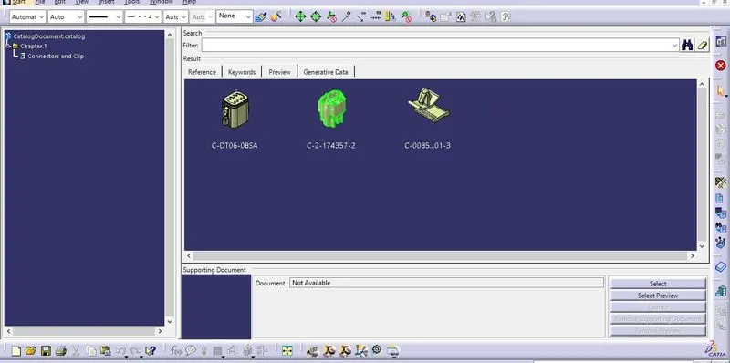
Step 4: Now create the Catalog document by opening File > New > Catalog document > then name the catalog file and add above connectors and clip one by add reference file option in catalog window. Sve this file by Ctrl +S.
- In electrical part design there is command called store device by selecting the catalog document and family we save part in the catalog document this is applied to every part.
- our Catolog document gonna look like this: