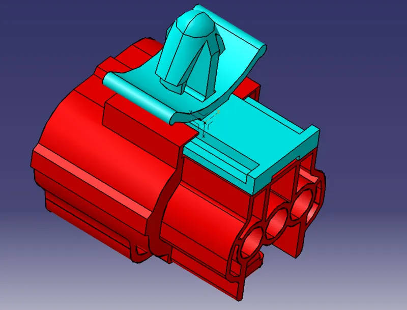
Wiring harness design in CATIA V5 - 3D modeling Week 2 Challenge
Aim: To download the following connectors & Connector clip cad data from the given link & define it as Electrical Connector using Electrical Part Design Workbench. Define all the necessary properties of Connectors & clips.
- Deutsch DT06 – 08SA ( https://www.te.com/usa-en/product-DT06-08SA.html)
- Tyco 174357-2 (https://www.te.com/usa-en/product-2-174357-2.html?source=header-match)
- Tyco 85229-1 – (https://www.te.com/usa-en/product-85229-1.html?q=85229&source=header).
Solution:
- Deutsch DT06 – 08SA ( https://www.te.com/usa-en/product-DT06-08SA.html)
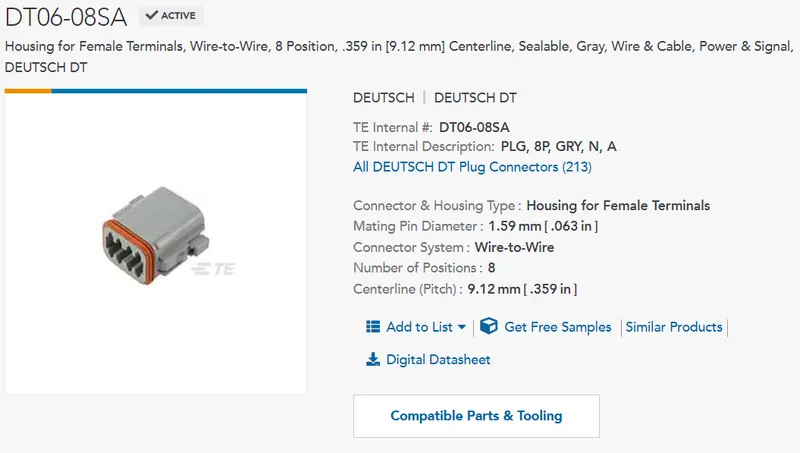
Download the following part and import it to the CATIA V5 software.
For downloading the file,
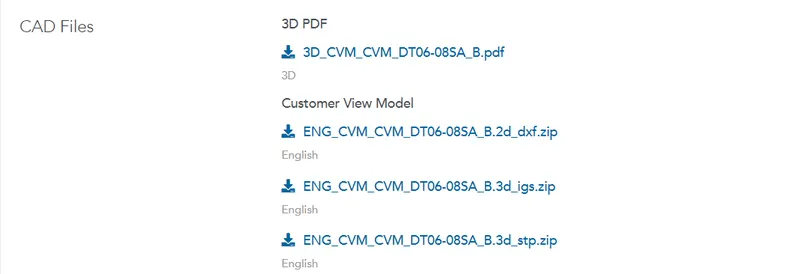
Select any zip files provided by the TE connectivity, and try to import the part in CATIA V5.
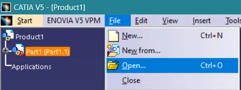
Select Open, go to the downloaded folder, and import the file.
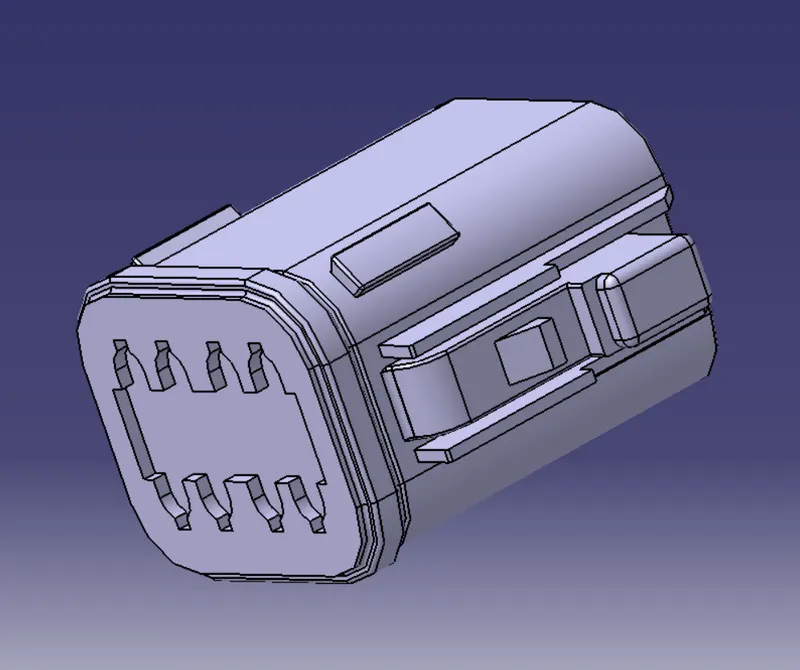
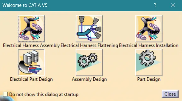
Step 1: Select workbench as Part Design Workbench
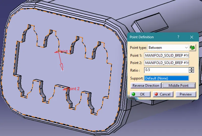
Step 2: To create a center point or midpoint in the connector connection point we need to select POINT, select point type as BETWEEN and select 2 points on the plane, choose midpoint and it will create a center point automatically.
Step 3: Axis system, Select ORIGIN as the point you just created above, choosing the x coordinate to be in the direction of the locking system, the y coordinate to be in the direction of the connector connection point, and the z coordinate to be in the rest.
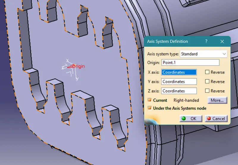
Rotate the axis according to our need, right-click on the selection tab where it says "Coordinates", go to the Rotation option, and rotate the axis.
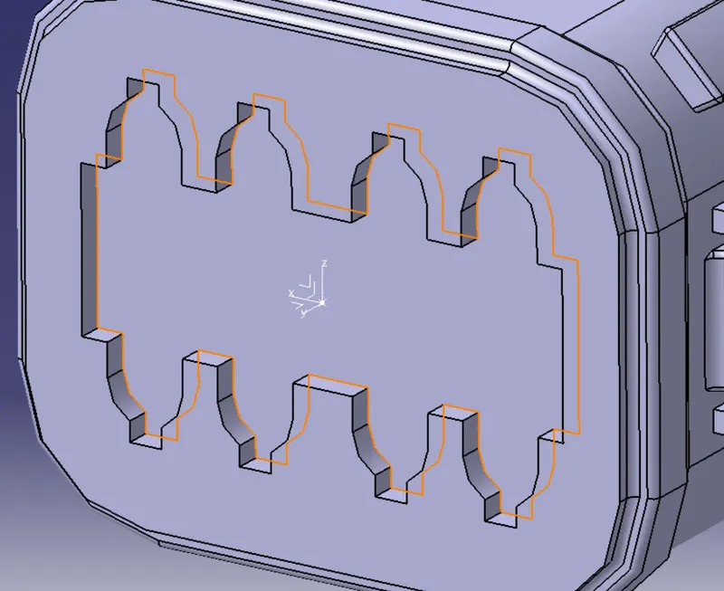
Step 4: Define the part as ELECTRICAL Part Design.
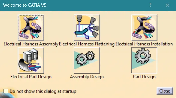
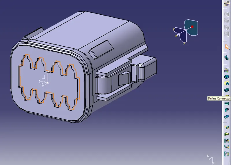
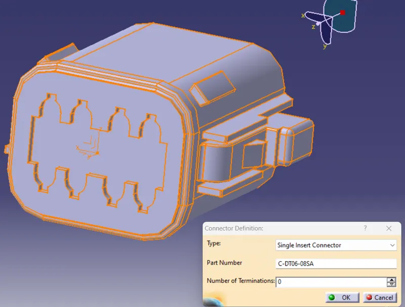
Step 5: Define the part as a connector,
Step 6: Define the Bundle connection point,
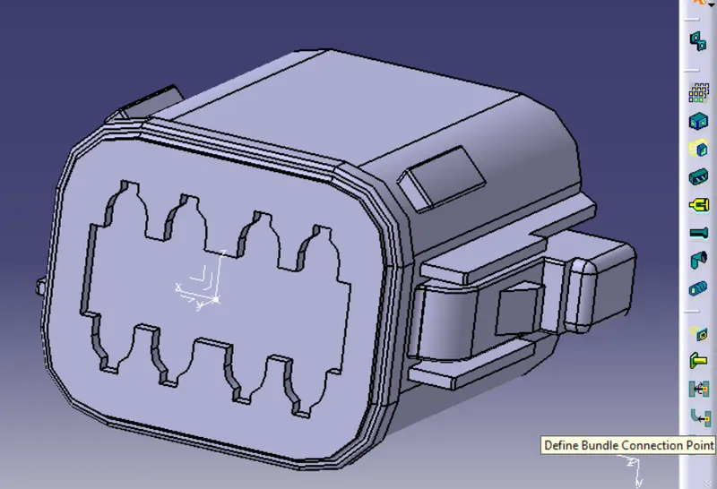
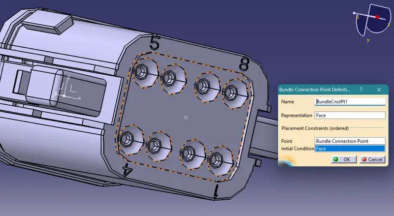
Representation: It will be always normal to the bundle entry point, the point from where the wiring will be entered into the part itself.
Point: The midpoint of the Bundle entry plane.
Initial condition: It can be any reference point, but generally we select the face normal to the bundle entry point to be crystal clear and do not get confused.
Step 7: Define the Connector Connection Point,
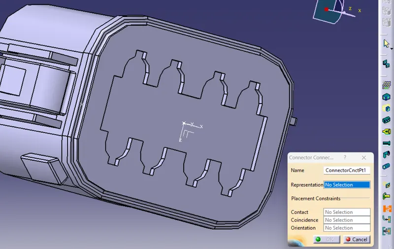
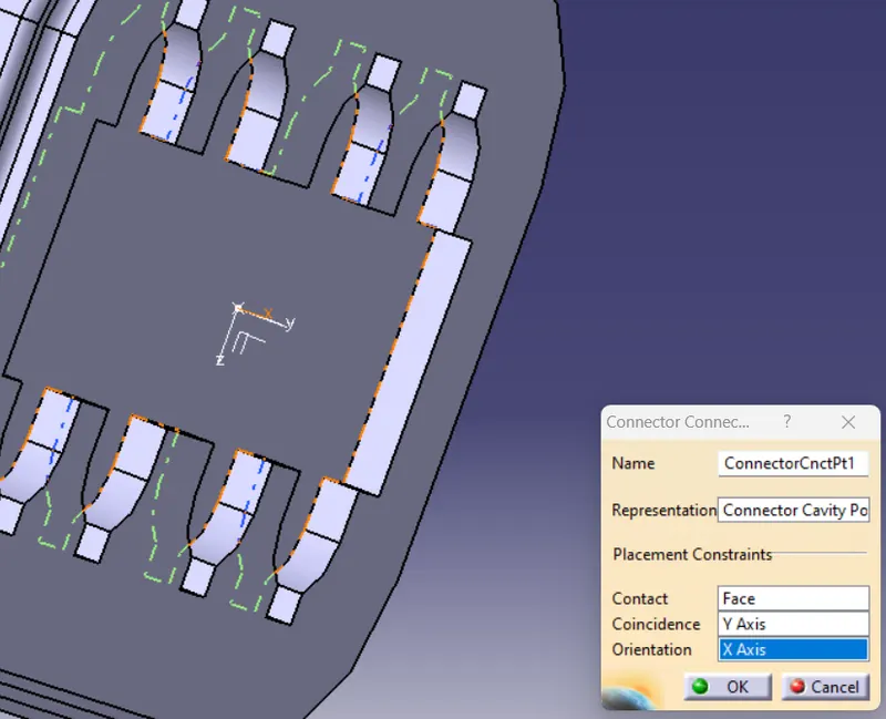
Representation: It will be the point (Center point or midpoint we created in steps 2 and 3).
Contact: The face of the Cavity Connector plane.
Coincidence: It can be any reference point, but generally we select the y-axis as we have assigned the y-axis as the mating direction, which means the parts will be assembled in this direction and the joints will be created.
Orientation: Again, it can be in any reference point, but generally we select the x-axis as we have assigned the x-axis normal to the locking system, it will ensure that the part will be oriented in this particular manner and it won't be rotated to any direction.
REPEAT (SIMILAR STEPS ARE FOLLOWED FOR ALL PARTS) THE ABOVE 7 STEPS FOR,
- Tyco 174357-2 (https://www.te.com/usa-en/product-2-174357-2.html?source=header-match) AND
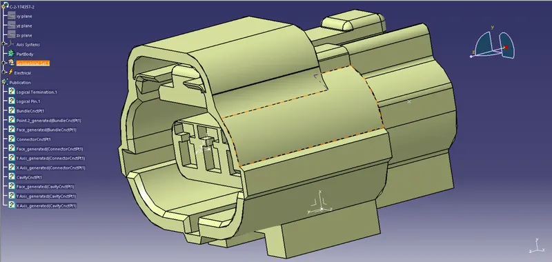
- Tyco 85229-1 – (https://www.te.com/usa-en/product-85229-1.html?q=85229&source=header)
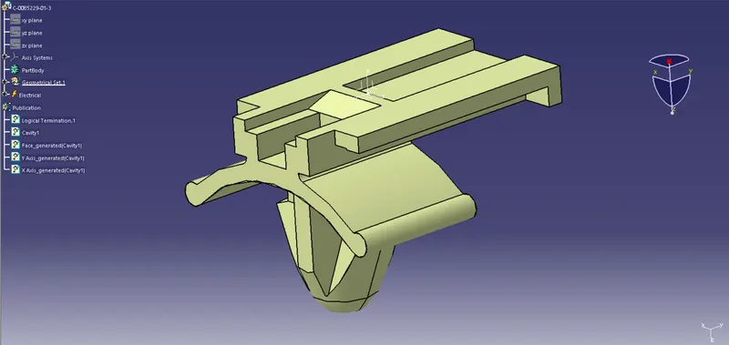
THE ASSEMBLY:

ISOMETRIC VIEW: