Project 1 (Double-Acting Actuator Model)
Aim:- To develop a double-acting actuator model using Simscape Multibody and Simscape components. The mechanical system of the cylinder needs to be built using Simscape Multibody library components/blocks, and the hydraulic system needs to be modeled using Simscape library physical components.
Objective:- The mechanical system of the cylinder needs to be built using Simscape Multibody library components/blocks, and the hydraulic system needs to be modeled using Simscape library physical components.
Solution:-
Actuators:- There are many types of valves and we choose according to the application of the syste, it’s important to know which kind of valve actuator your project requires. In an automated valve assembly, the actuator is the component that causes the valve to open or close. Valve actuators can be triggered by electricity, hydraulic pressure, or air (pneumatic) pressure. Although single-acting hydraulic and electric actuators do exist, the term single-acting is most commonly used to describe pneumatic actuators.
-- What Is a Single-Acting Actuator?
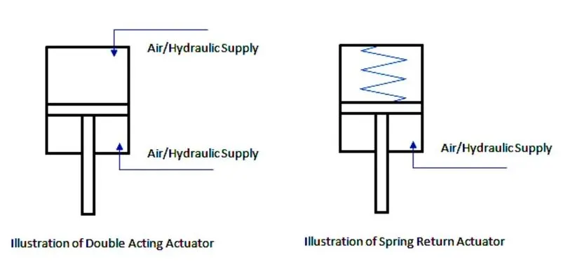
Commonly referred to as spring-return actuators, a single-acting pneumatic actuator uses air to open the valve and a mechanical spring (or springs) to close the valve. The actuator can also be configured inversely so that air closes the valve and the spring is used to open the valve; this is called a normally-open configuration.
The most common reason single-acting actuators are chosen is for their reliable fail-safe design. This means that if power or air pressure is lost, the valve will quickly move to the normal position. This is useful in applications where serious consequences may occur if the valve remains open (or closed) when power and/or air pressure is lost.
Three drawbacks to single-acting actuators are:
- The inclusion of mechanical springs in the design adds additional cost to the valve assembly. The cost difference depends on the size and style of the valve.
- The springs are susceptible to fatigue and will usually be the first component in the actuator to fail. Therefore, single-acting actuators are generally considered to be less durable than double-acting actuators.
- The spring modules give the actuator a larger form factor that may not be compact enough to fit into some applications.
-- What is a Double-Acting Actuator?
Unlike single-acting actuators, double-acting actuators use air pressure to both open and close the valve.
This is the most popular style of the pneumatic valve actuator. Double-acting actuators are selected for their lower cost and superior longevity since the absence of mechanical springs in most models eliminates the least durable component in the actuator. It is not uncommon for a high-quality double-acting actuator to cycle millions of times before failing.
-- When to use a Double-Acting Actuator?
Double-acting actuators are ideal for high cycle applications and/or applications where the valve failing to the closed (or open) position when power is lost does not present a critical issue. Double-acting actuators are the most popular choice for their lower cost and superior longevity. Double-acting actuators are also more compact than single-acting actuators and may be the only option in small form factor applications.
- Single Acting Vs Double Acting Actuators:-
- Double-acting actuator model:-
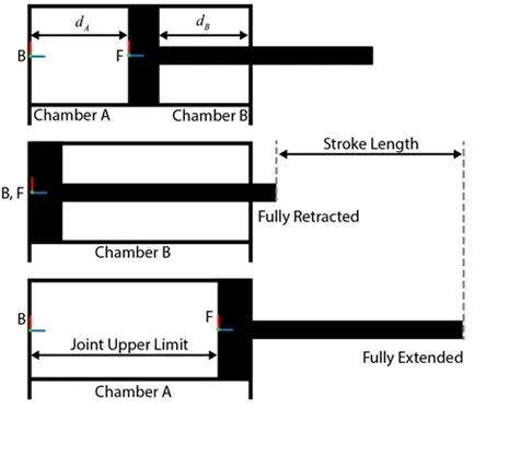
- The following Cylindrical Model Schematic shows the three different configurations of the piston
- Half Retracted, Fully Retracted, Fully Extended
MODEL:-
- The model of Double acting Actuator developed using Simscape Multibody and Simscape components are shown below.
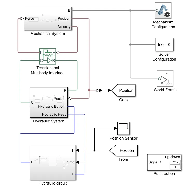
- MECHANICAL SYSTEM SUBSYSTEM
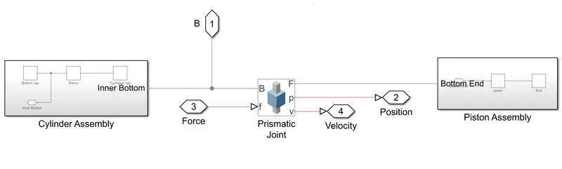
- Cylinder Assembly
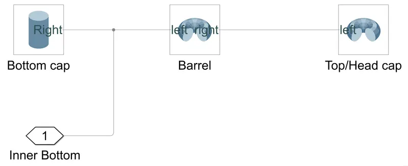
-- Inside Cylinder Assembly we have mechanical system designs and the parameters of those are as follows:-
1) Bottom cap: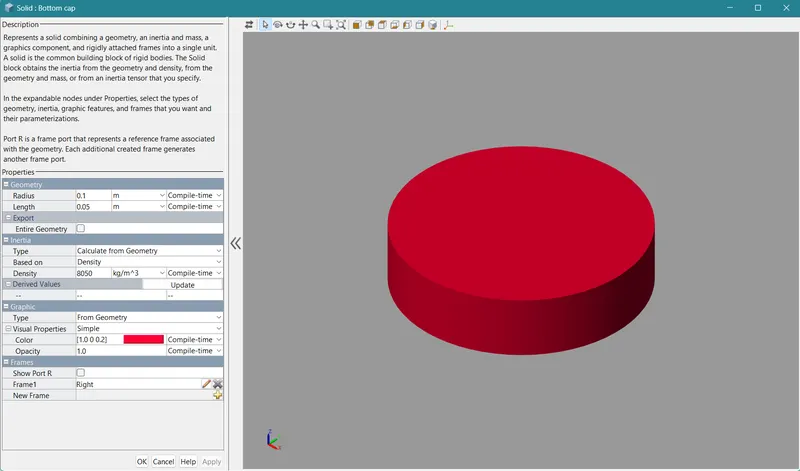
2) Barrel: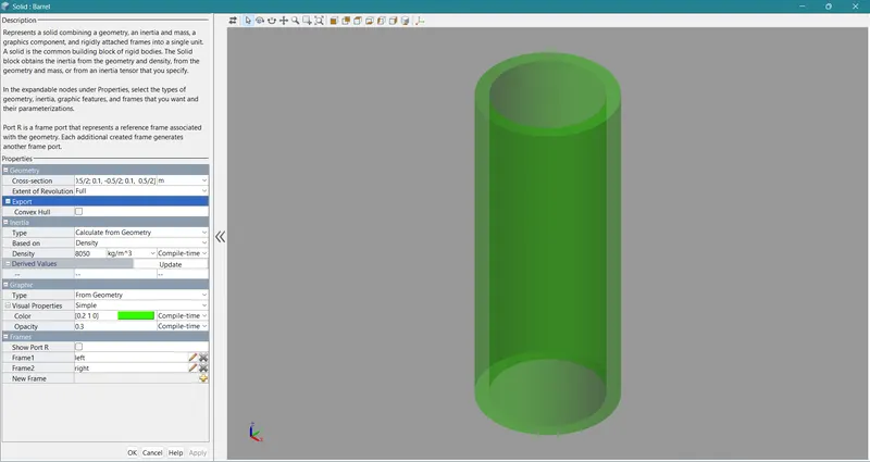
3) and Head cap or Top cap: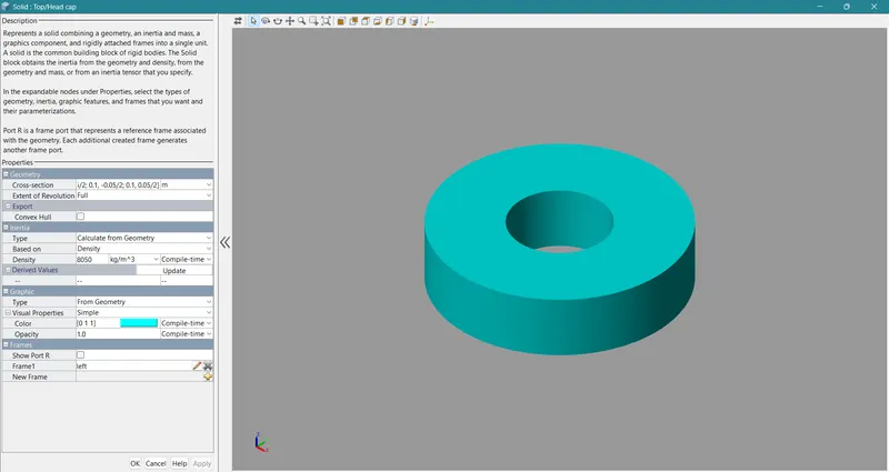
- Prismatic Joint
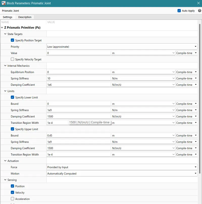
- Piston Assembly
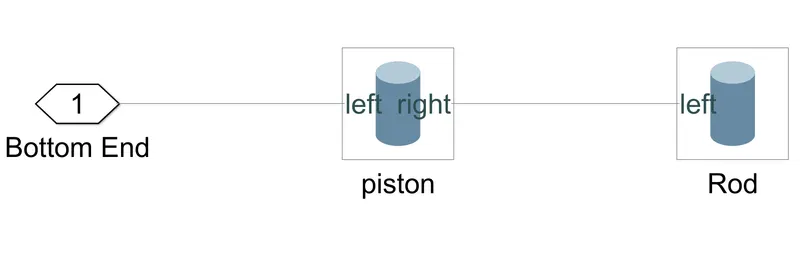
Also inside Piston Assembly, we have mechanical system designs and the parameters of those are as follows:-
1) Piston: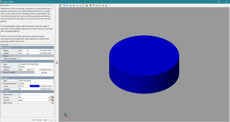
2) Rod: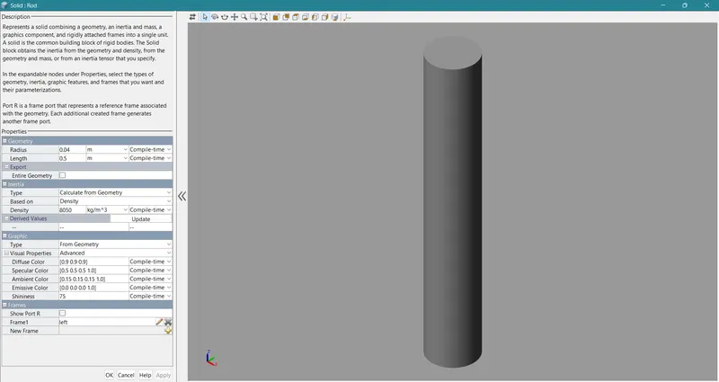
- HYDRAULIC SYSTEM SUBSYSTEM
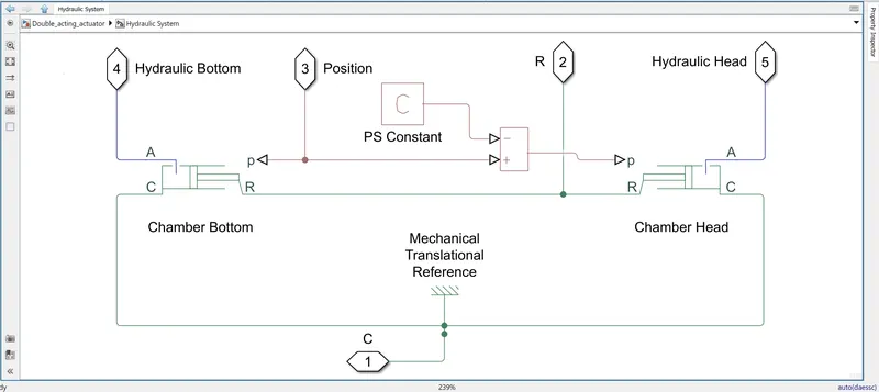
1) Chamber Bottom: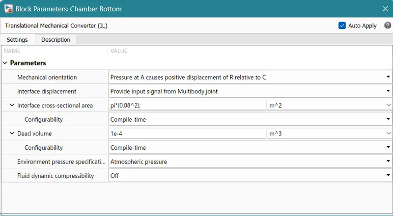
2) PS Constant: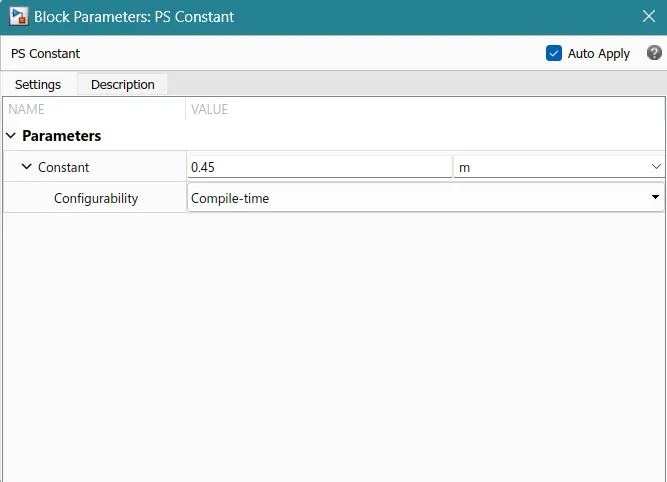
3) Chamber Head: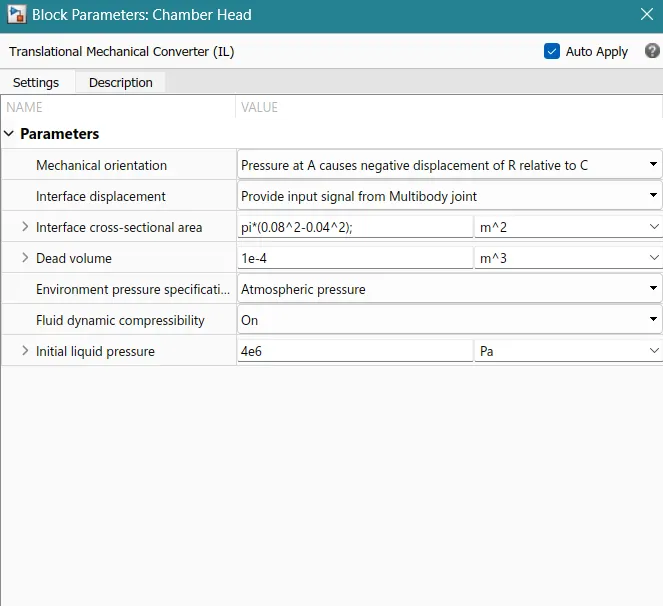
- HYDRAULIC CIRCUIT SUBSYSTEM
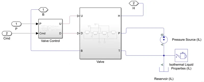
1) Valve Control: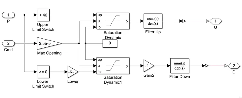
2) valve: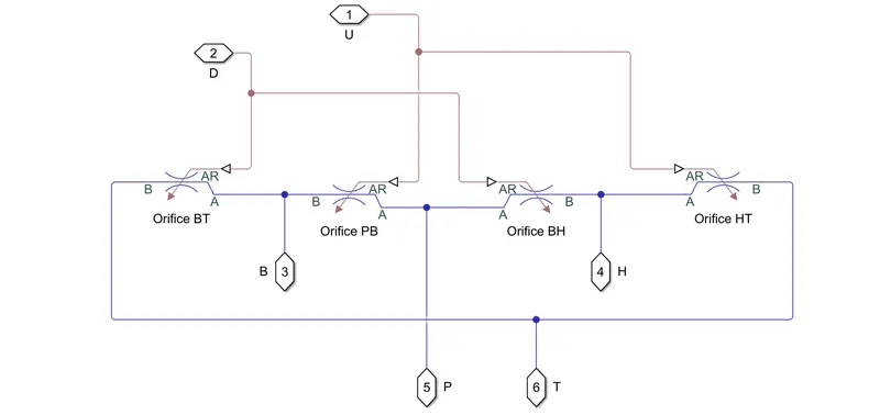
2) a) Orifice BT: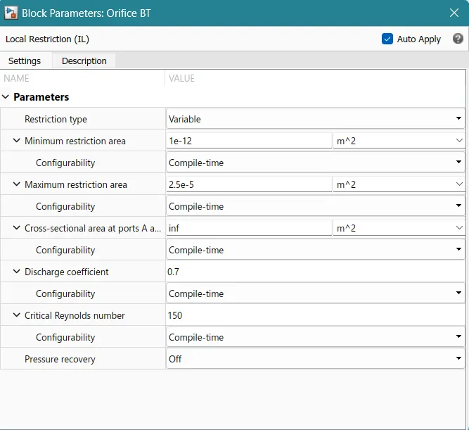
2) b) Orifice PB: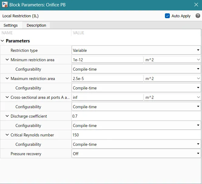
2) c) Orifice BH: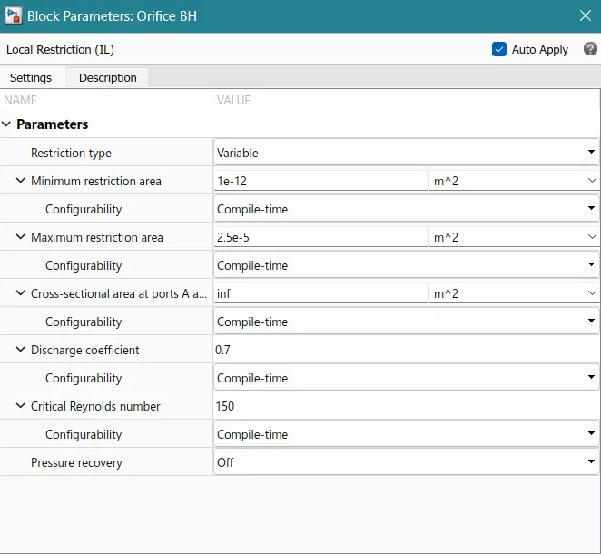
2) d) Orifice HT: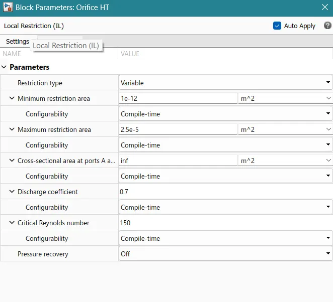
3) Pressure Source: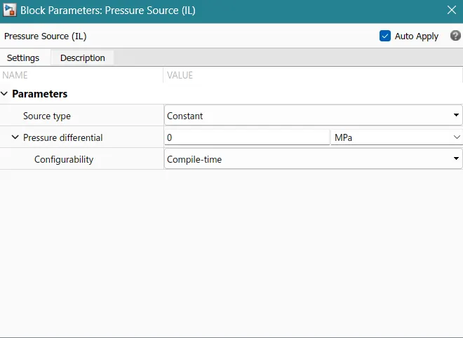
SIGNAL BUILDER: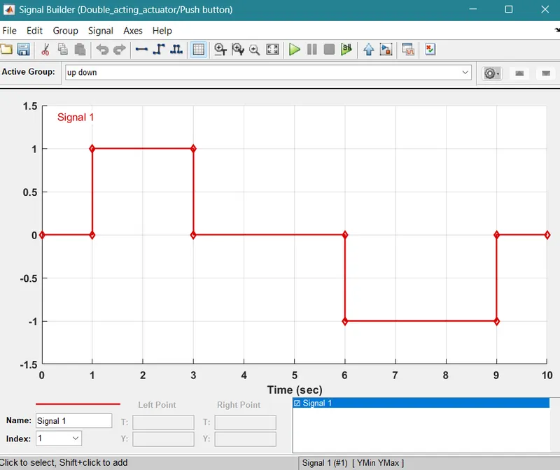
- RESULT
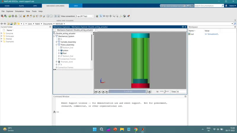
- REFERENCE MODEL
-- https://in.mathworks.com/help/physmod/sm/ug/hydraulic-interface-dump-trailer-with-hydraulic-cylinder.html