Wiring harness design in CATIA V5 - 3D modeling Week 2 Challenge
Connector
Loaded the connector model from the link
Tyco 174357-2
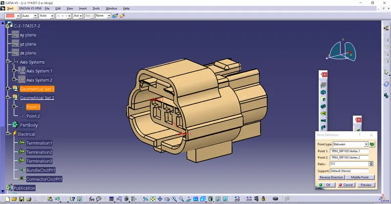
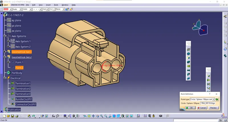
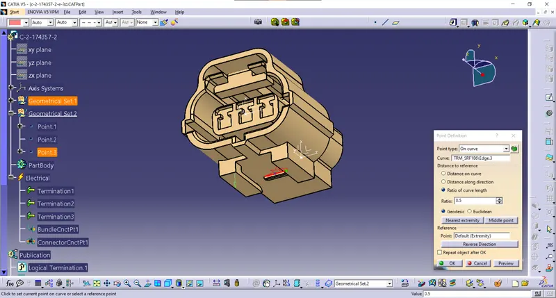
Loaded the part in mechanical Design in part design and insert centre point using point option
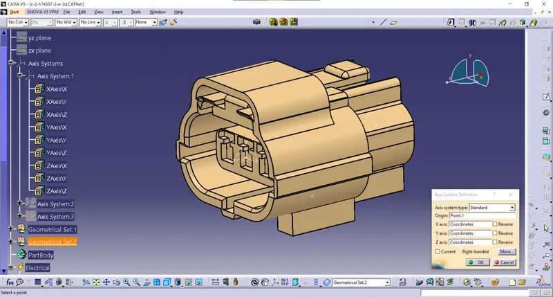
And inserting Axis system in point
First connector connection side
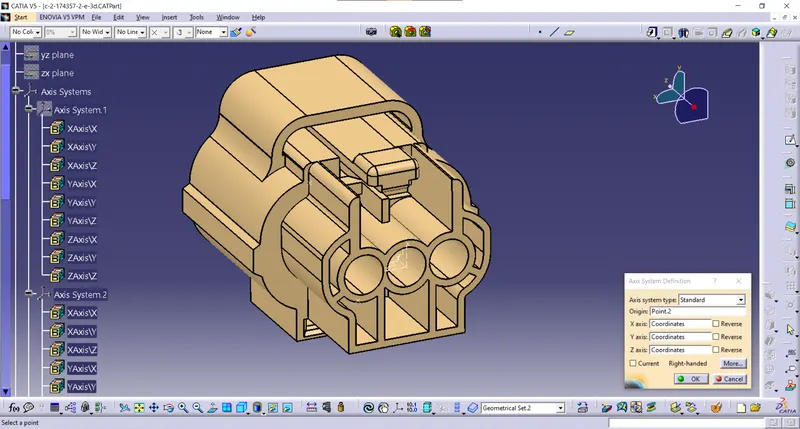
Axis system on Bundle connection side
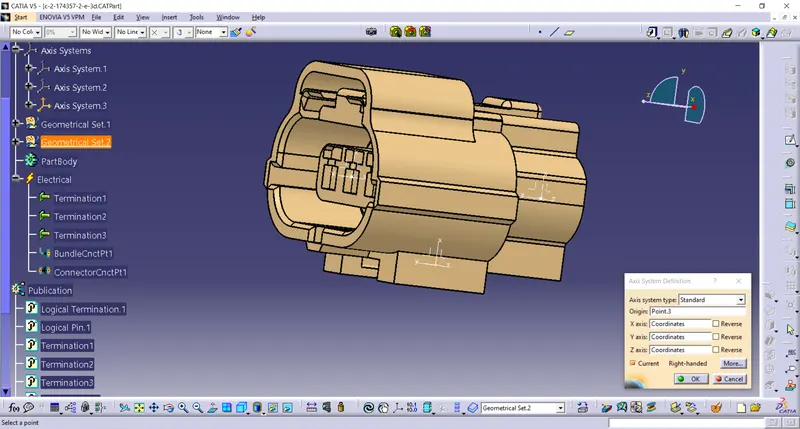
The cavity connection side
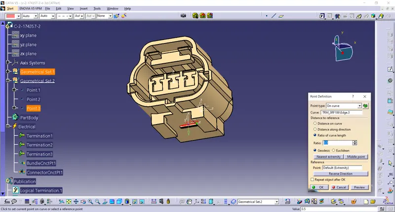
the Axis system X-axis rotated 90 degrees to make Y-Axis Coincidence for Assembly requirement
Part Design to Electrical part design
defines it as a 3-terminal connector
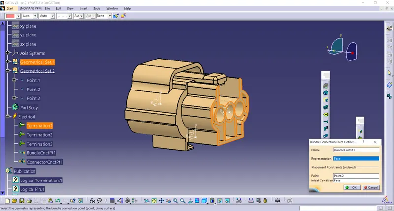
the Bundle connection point is defined on the Bundle connector side.
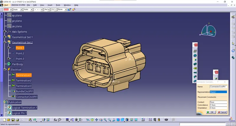
The connector connection side is defined as the connector connection point.
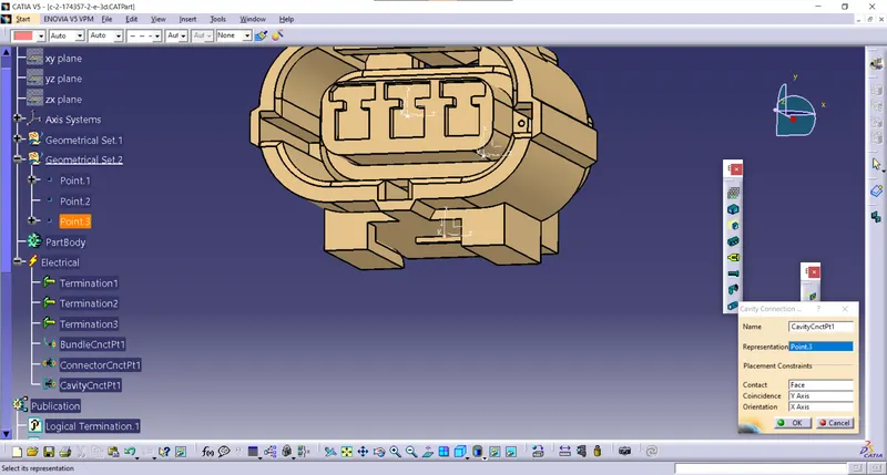
The cavity connection side is defined as a Cavity connection point.
Connector 2
Loaded the connector model from the link
Deutsch DT06
First, I loaded the model from the given link.
Deutsch DT06 – 08SA
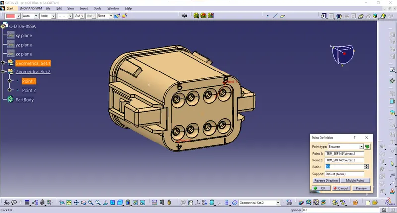
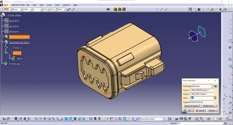
Insert center point using between two point option
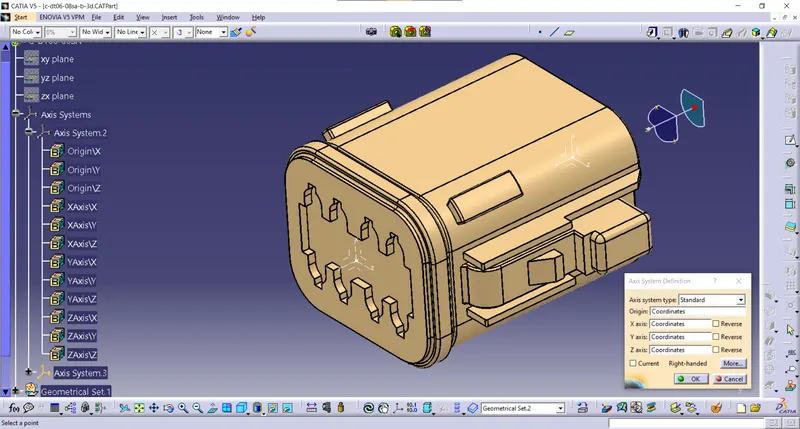
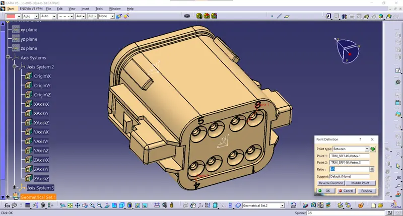
Given Axis System connector connection side.
the Axis system X-axis rotated 90 degrees to make Y-Axis Coincidence for Assembly requirement
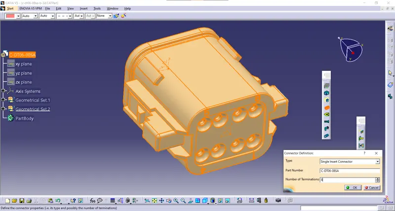
convert from Part design to Electrical part design Then model defines as an 8-terminal connector.
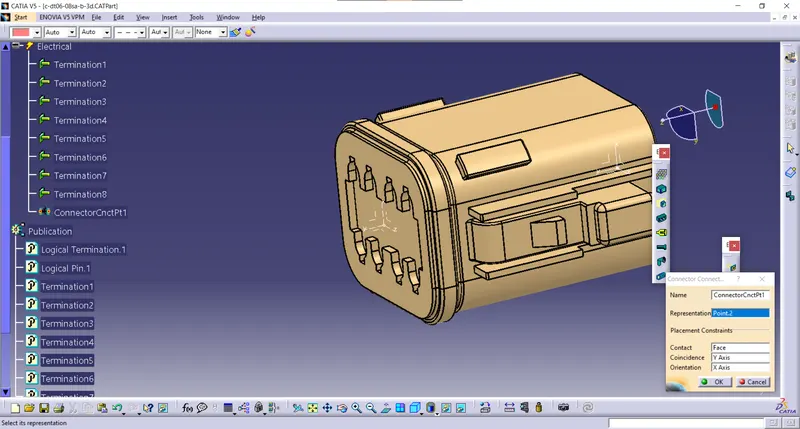
The connector connection side is defined as the connector connection point.
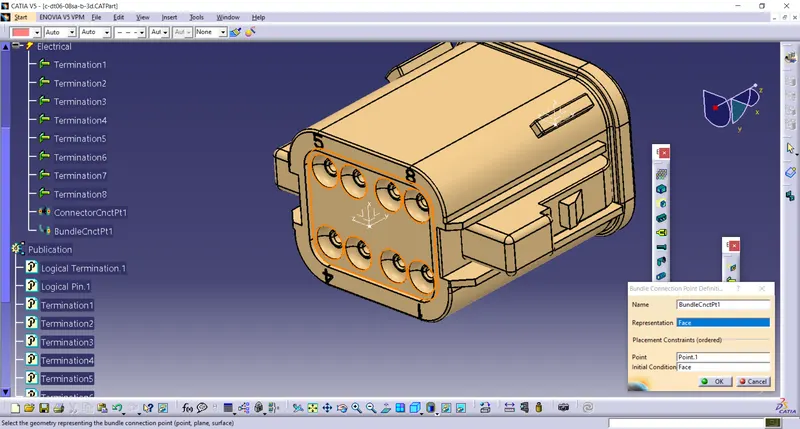
Then Bundle connection point is defined on the Bundle connector side.
Tyco 85229-1
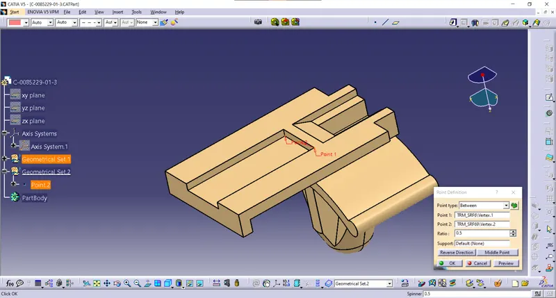
part design given a Center point with help of Between point.
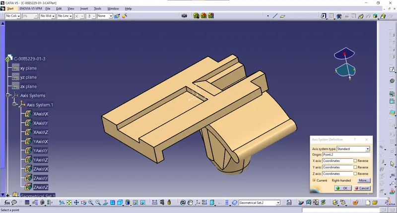
Given the Axis System Mounting side.
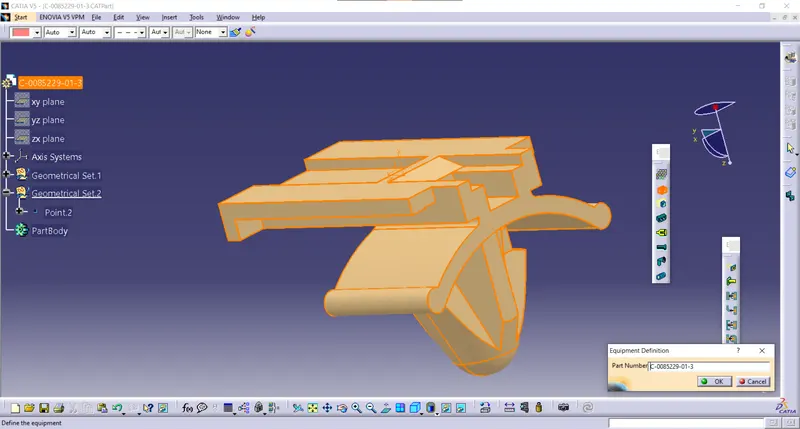
convert it from part design into electrical part design and define it as Equipment.
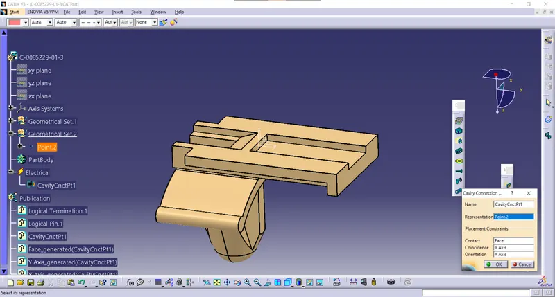
The mounting Side is defined as cavity definition.
Now create an electrical assembly design product file import the connector 1 and mounting clip part
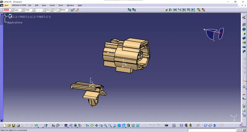
Rotate the mounting clip along the x-direction to match the connector 1.
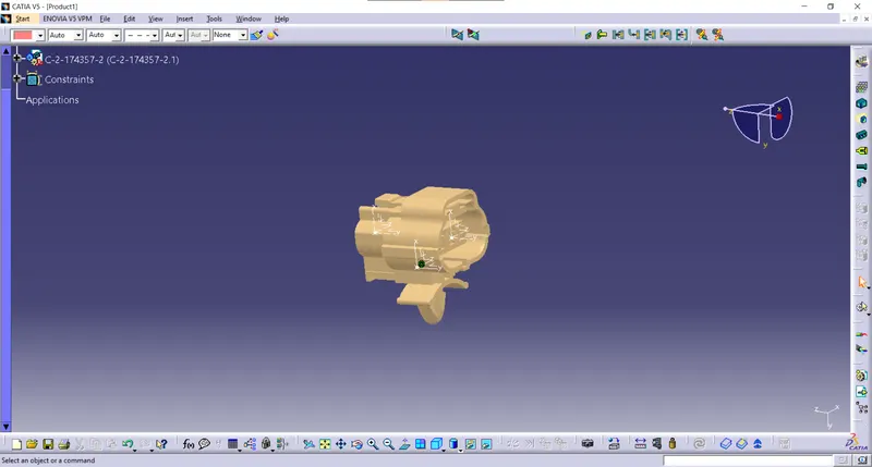
Now click on connect electrical devices command and select the two parts. The parts are connected specified direction.