Wiring harness design in CATIA V5 - 3D modeling Week 2 Challenge
Aim : To define the connectors and connector clips as Electrical connector using Electrical design workbench. Define all necessary properties to connectors and clips.
Explanation : The following parameters are required to be defined for any Connector/Clip.
1. Geometry parameters : Point definition and Axis System definition (Co-ordinate system).
2. Connector Connection point : this is used for the connection of one connector to another connector.
3. Harness Bundle entry point : This point defines where the harness bundle segment point will end when routed to the electrical connector.
4. Cavity Connection point (Optional) : This point is used to define the connection of a segment to a connector clip. This only applies to connectors which have the mounting feature for a connector clip.
1. Geometry Parameters : For this, first we have to download all the component files from the links provided above. We have to download the .igs files. Incase of zip files , extract the files .
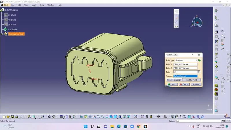
a) Point Definition : Open the CATIA software. Go to Part Design workbench and go to File and Open the .igs file of the component. The part opens in the workbench. We start with Point definition. To define , first create a point definition at the connector end. Click on point . A window named " point definition " opens up. Select the appropriate point type and create the point based on the point type. In the example below we have used " Between" as the point type. Select the two points and create a middle point. Click Ok. Point definition of the connector end is created. see illustration below.
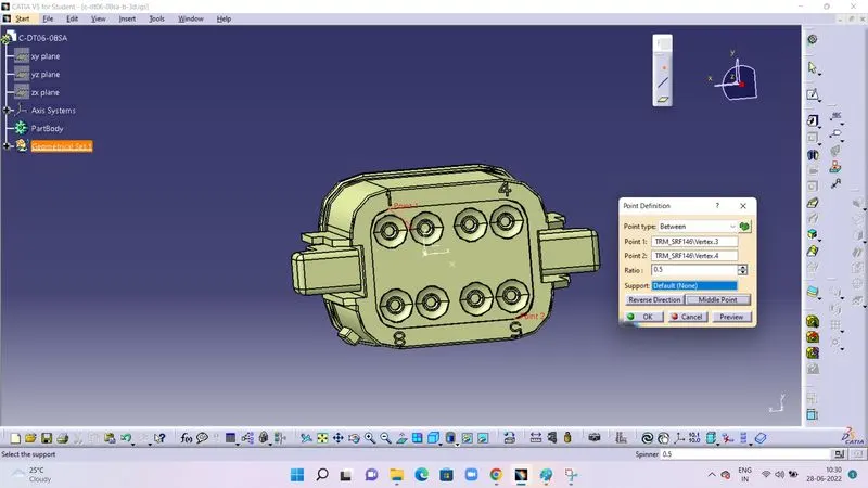
Now , we have to follow the same procedure of Point Definition and create a point at the bundle entry end. See image below.
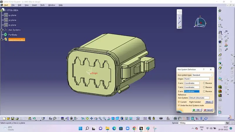
b) Axis Definition : Axis system definition is done on the connector side/mating surface end. Click on axis system and a window named " Axis System Definition " opens up. We have to select the appropriate Axis system type. Here we have selected as standard. To select origin , go to the point defined on the connector end and select that point as the origin for the axis system. Now , we will adjust the orientation of the x , y and z axis. We have taken x axis in the direction of the locking mechanism , y axis as normal/perpendicular to the mating surface and z axis as across the connector. Once the orientation of all the axis is defined click OK. see image below.
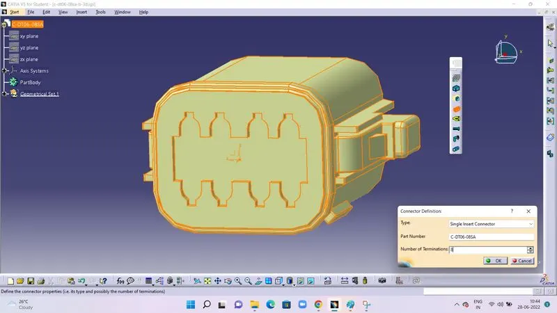
2. Define Connector : Now , since all the geometry parameters are defined we have to define this part as a connector. For that we changeover to Electrical part design workbench. As we are in Electrical part design go to Define Connector . Click on the part and a window named " Connector definitions" opens up. Select the appropriate Type and input the Number of Terminations and click OK. Now the connector is electrically defined. see image below.
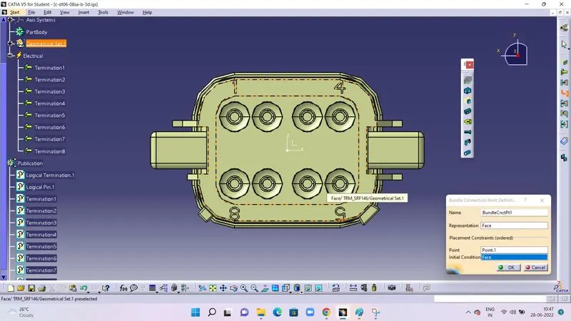
3. Bundle Connection Definition : Go to Define Bundle Connection point. Note that if you do not Define connector you wont be able to proceed to this process as it requires the connector to be electrically defined. Click on Define bundle connection point and then click on the connector. A window named Bundle connection point definition opens up. In Representation select the harness entry face of connector. For the point select the bundle entry point and the initial condition will be again the bundle entry face of the connector. click ok. See image below.
4. Connector connection point : Go to the connector connection end. Click on Define connector connection point. click on the connector. A window named Connector connection opens up. In Representation , select the connector connection point as the point defined. Select the mating face as Contact. In coincidence select y axis and in Orientation select x axis. Click ok. See image below.
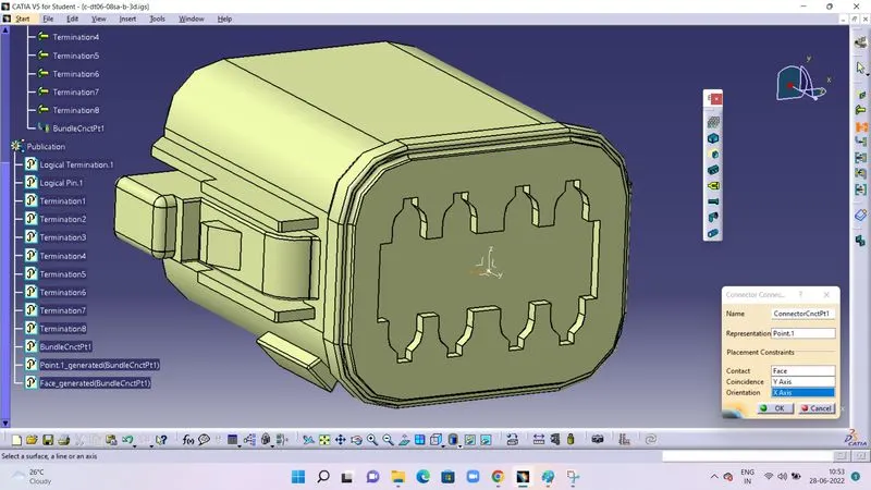
Ensure that the mating connector also has the same coincidence and orientation as the y axis and x axis.
Save the File. The same procedure should be used when defining other connectors.
Incase ,there is a connector which has a cavity for a mounting clip , the additional cavity definition is to be done for both , the connector and the mounting clip.
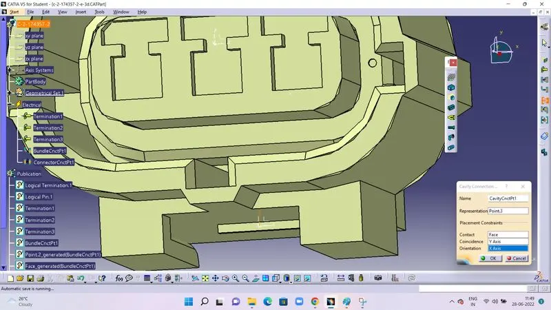
5. Cavity definiton for connector : First we define the cavity connection point for the connector. Check the locking mechaninism of the connector. This lock will be used to define the cavity connection point. Go to the connector window in tools and follow the process for Point and Axis definition at the locking face which will mate the mounting clip. This is done in part Design workbench. After the point and axis definiton go to the Electrical part design workbench. Click on Define cavity connection point and then click on the connector. A window named Cavity connection... opens up. In representation select the point defined. In contact select the mating face. Coincidence is y axis and orientation is x axis. Save the file. see image below.
6. Cavity definiton for mounting clip : Now, we have to define the mounting clip as a cavity. In part design workbench open the .igs file of the mounting clip. Define the Point and Axis system. Ensure that the direction of all the axes is in the same direction as that of the connector lock. Click ok. Now , we define the clip as an electrical part.
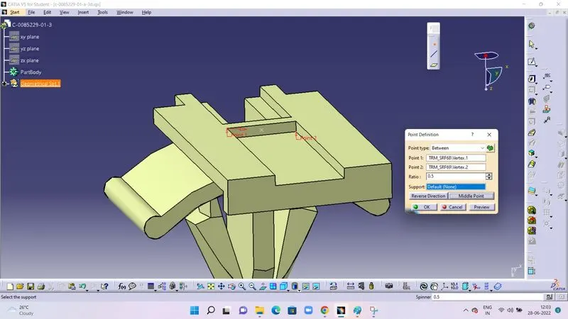
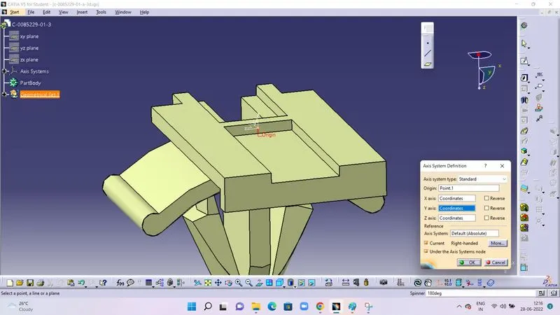
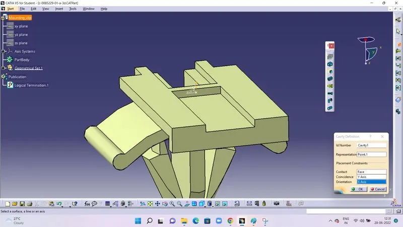
Go to Electrical part design workbench and then go to Define mounting equipment. Click on the part and click ok.
Go to Define cavity and then click on the part. In representation selct the point and in contact select the mating face. In coincidence select y axis and in orientation select x axis.click ok and save the file.
Conclusion : Below is the link to google drive where the .CATPart files are present.
https://drive.google.com/file/d/1VQqGM-vL_RYVfELDlofEvwoZEbSnxcWW/view?usp=sharing