Wiring harness routing & packaging Rules Week 3 Challenge
Aim :
1. Define the given component (P Clamp) as a Electrical support using Electrical part design workbench and define all necessary parameters.
2. Define Backshell as Electrical back shell using Electrical part design workbench and define all the necessary properties.
3. Create a Catalogue for the given Corrugated tubes and add them under the " Slit COT' family.
1. Defining the P Clamp as a Electrical support :
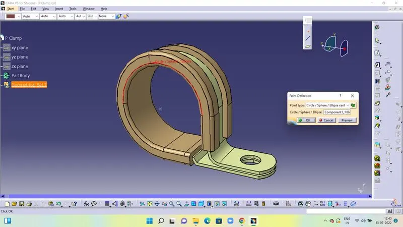
First we open the downloaded .igs file of the P Clamp in Part Design. Before Starting , delete any previously defined planes and points. After that we go to point definition and then create point definition on both ends of the P Clamp. Click Ok.
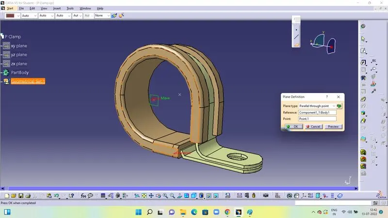
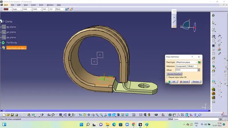
Now we have to create plane definition for the Entry , Exit and Base of the P clamp. Click on Plane and a window named plane definiton opens up. Select the plane type. select parellel through point. For the Entry and Exit plane definition the Reference will be the Entry and Exit face. Then in the point option select the point defined for that particular plane. Click ok. Now we have to define the base plane. Click on plane. In plane type select offset from plane. In the reference select the face of the base. Enter the offset distance of the plane from the base. here we have taken as 2 mm. click ok. Save.
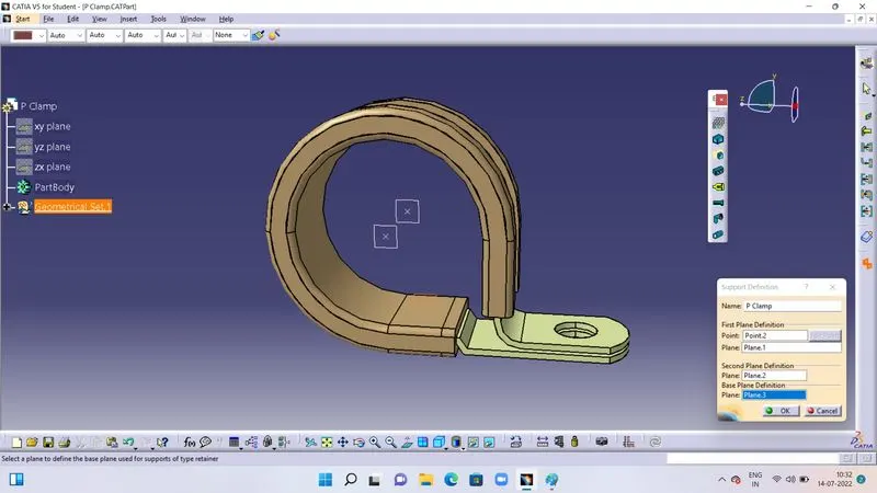
After the clamp has been defined for the properties, we have to define the clamp as an electrical part. First we define as an Electrical support. Go to Electrical part design workbench. go to Define support part. A window named support definition opens up. In the first plane definition (Entry) select entry point and then the entry plane. Then in the second plane definition select the exit plane. In base plane definition select the base plane. click ok. Since there are 2 entry and 2 exits we have to define from the other side also. You will see the updated tree structure. Save the file. The P Clamp is electrically defined.
2. Defining Back Shell as an Electrical Part :
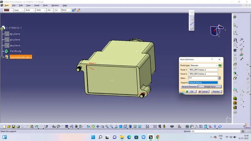
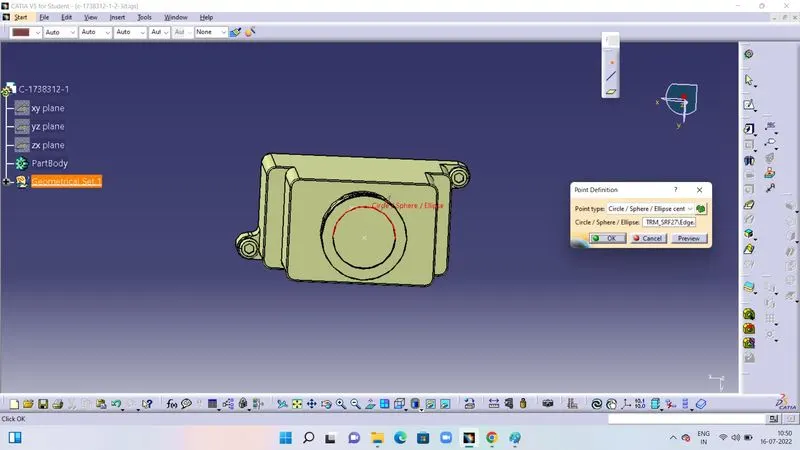
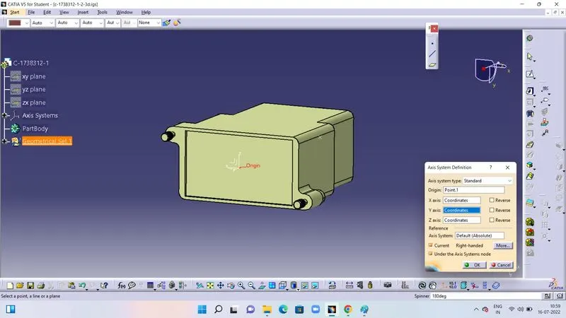
We open the .igs file in the part design workbench. First we define points for the connector end(ie the mating surface) and then we define for the bundle entry end. Next we define the axis at the connector end. Origin of the axis system should be defined on the location which is going to be the mating surface of the connector.
Point definition for connector end.
Point definition for bundle entry end.
Axis Definition.
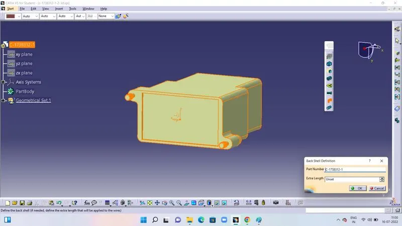
Now we go to Electrical part design workbench. Click on Define Backshell. A window named BackShell definition opens up. We keep the settings as it is. click ok. Now the part is defined as an electrical part.
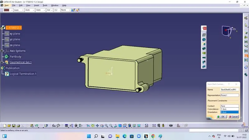
Next we click on Define Back Shell connection point. A window named BackShell connection opens up. We keep the name as it is. In representation we select the point created at he exit point. In contact we slect the mating surface. Coincidence is y axis and orientation is x axis. Click ok and save the file.
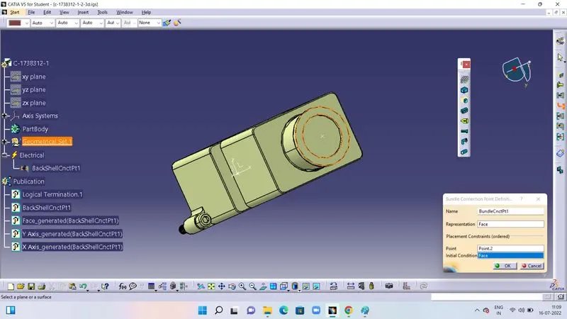
Now we go to Define Bundle connection point. Click and then a window named bundle connection point definition opens . Name as it is. Representation is the mating surface. point is the point defined at entry of bundle end. Initial condition is again the face. Click ok and save the file.
Now the part is fully defined as an BackShell.
3. Creating Corrugated tubes , Catalogue and adding them in the catalogue :
Corrugated tubes come under the category of protection covering , conduits. In the case of protection covering we are not going to deal with downloading data from TE.com. Instead we create a corrugated tube based on the size or the diameter required for the creation of the covering.
Creating a corrugated tube :
First we go to file and click on new. Then we select 'part' from the list of types . A window named New part opens. Name the covering based on the dimension to be created ,example COT_10mm,COT_15mm , COT_20mmetc. Enable hybrid design . click ok.
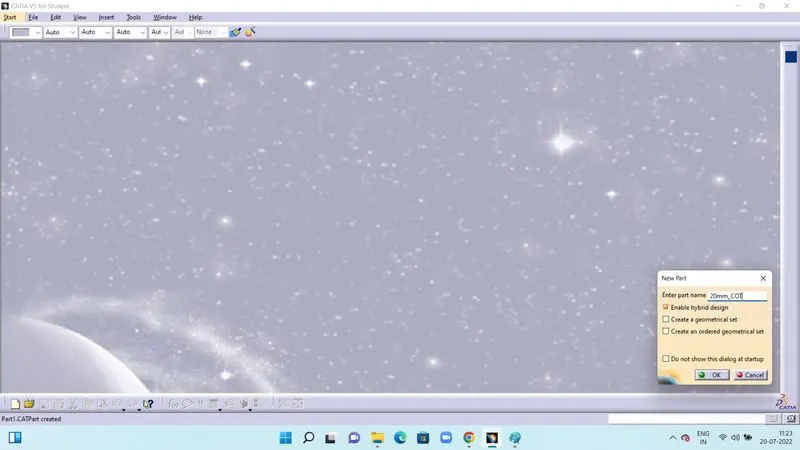
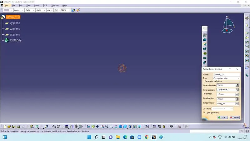
Next we switch to Electrical part design workbench. Click on Define protection part. Then in the tree structure click on the part body name ie example COT_20mm. A window named Define protection part opens. Keeping the name as is. Select the type as Tape or Corrugated tube. Here we select corrugated tube. Inner diameter is already given , hence we select as per given dimension. Inner section is automatically calculated based on the Inner diameter. Thickness is also given as per dimension. Bend radius is 1.5 times of the given external diameter. We select the various line type based on the requirement. Keep light geometry enabled. click ok. save.
Creating a Catalogue document :
Go to File and select new. Select 'catalogue document'. Click ok. A new window opens. Go to Add Family and a window named Family Definition opens. Here, in the Name we write it as CORRUGATED_TUBES. Select type as Conduit. Click Ok. Save the catalogue Document where we have stored the Corrugated tube parts.
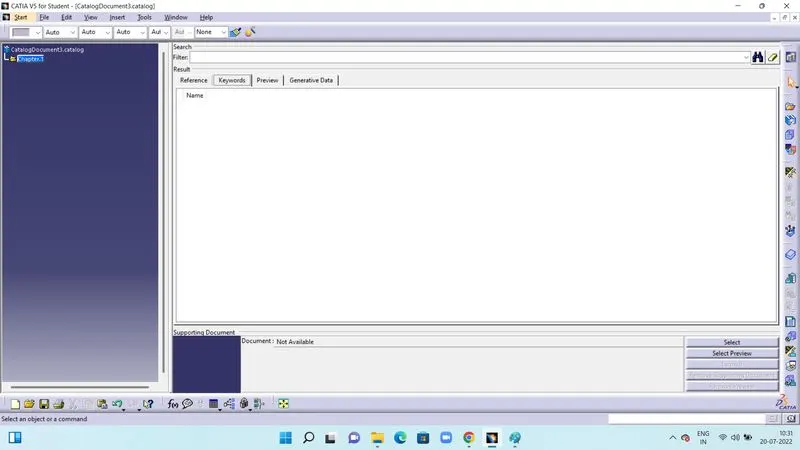
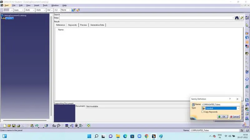
Adding the Corrugated Tube in the Catalogue Document :
Go to Store device. A window named Device Storage opens. In Catalog , browse the Catalogue Document created and saved for Corrugated Tubes and select it. Select the family as SLIT COT as mentioned. Click ok. Similarly save rest of the Corrugated tubes in the catalogue document.
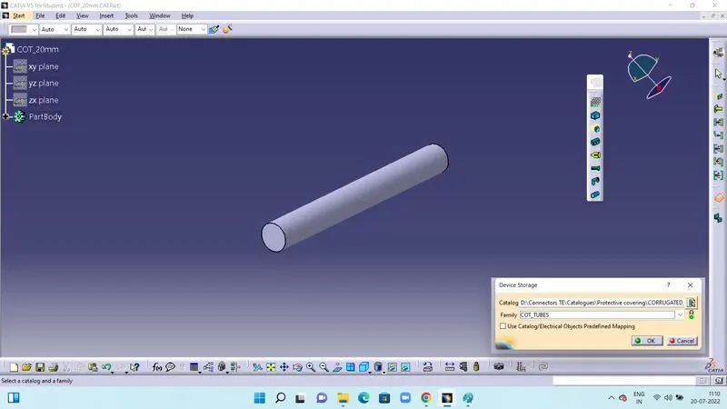
To check whether the tubes are stored in the catalogue first we go to part design workbench. Then we click on catalog browser. In the current folder go to saved document folder. We will find all the saved Corrugated tubes.
The SLIT COT catalogue document is attached in the attachments.