Wiring harness design in CATIA V5 - 3D modeling Week 2 Challenge
Wiring harness design in CATIA V5 - 3D modeling
AIM:
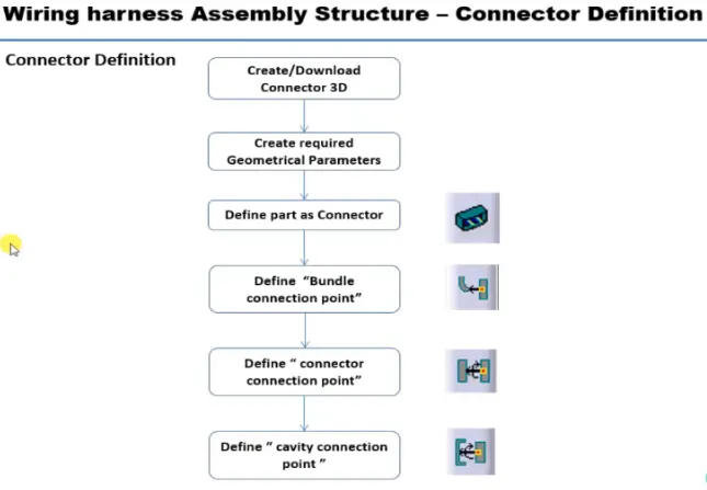
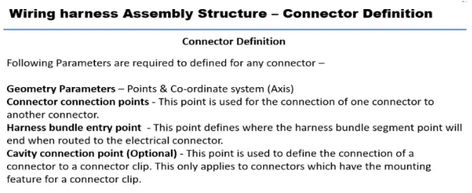
To Download following connectors & Connector clip cad data from given link & define it as Electrical Connector using Electrical Part design Workbench. Define all the necessary properties to Connectors & Clip.
- Deutsch DT06 – 08SA
- Tyco 174357-2
- Tyco 85229-1
PROCEDURE :
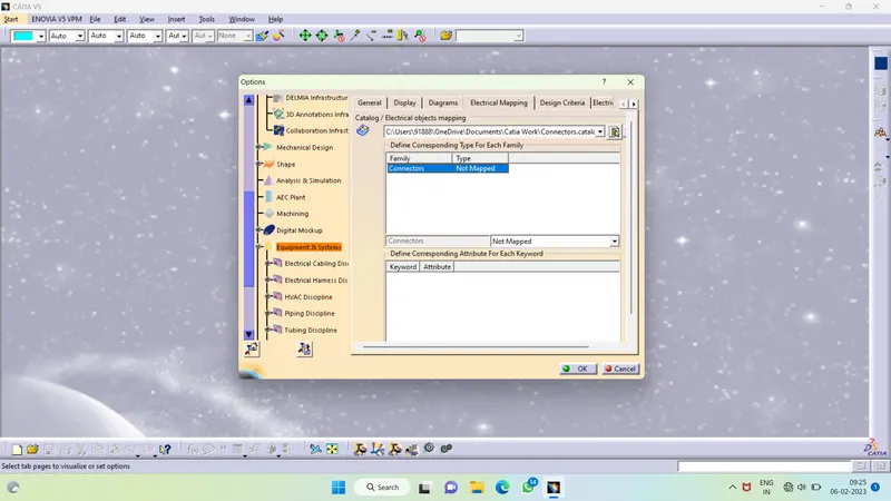
Creating a catalog for connectors :
Go to File>New>CatalogDocument
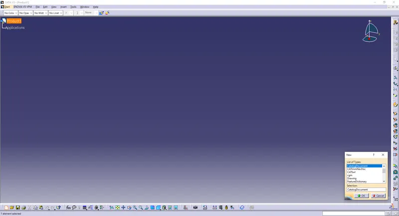
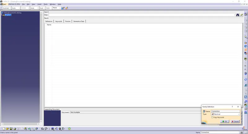
Name it Connectors
Type : Electrical
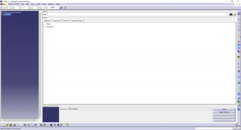
Save it to the desired location.
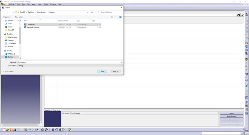
Now, we can save the imported or downloaded connector in the connectors catalog to use it in the future.
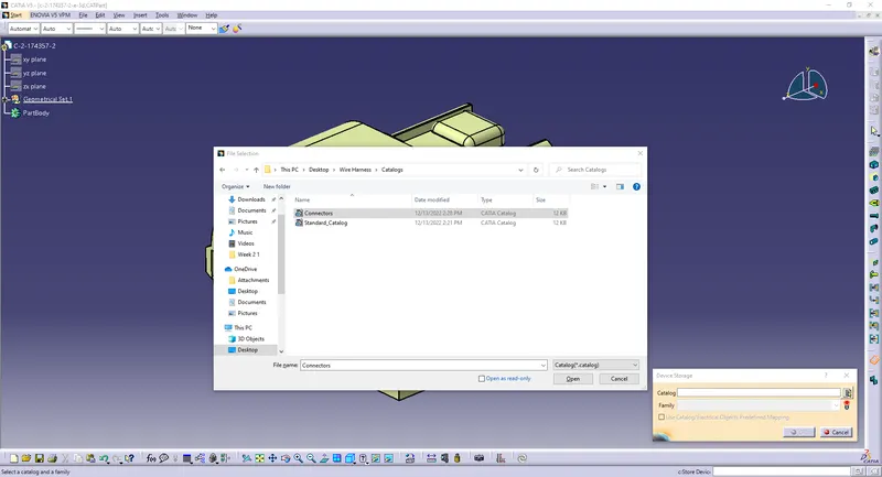
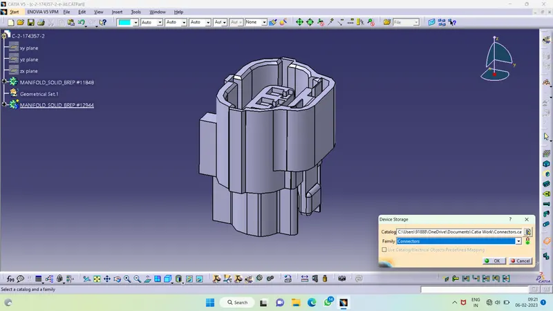
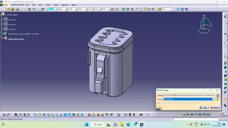
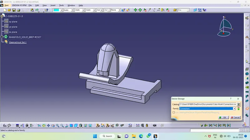
Then add connector family for electric mapping
Routing Procedure :
- First download the given CAD data.
- Define it as electical connector or cavity depending upon how the component is going to work.
- Then create a mounting point on the connector and create axis system on the point.
- Make sure that the direction of the axis system should be lie according to the conectors.
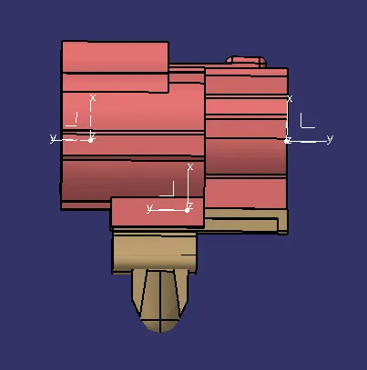
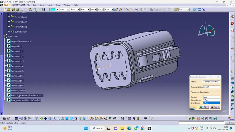
- Here X is point toward the left because the locking mechanism is in the sides of the connector and Y should point the direction from where the bundle and mating part is going to connect. According to the X and Y we can direct the Z.
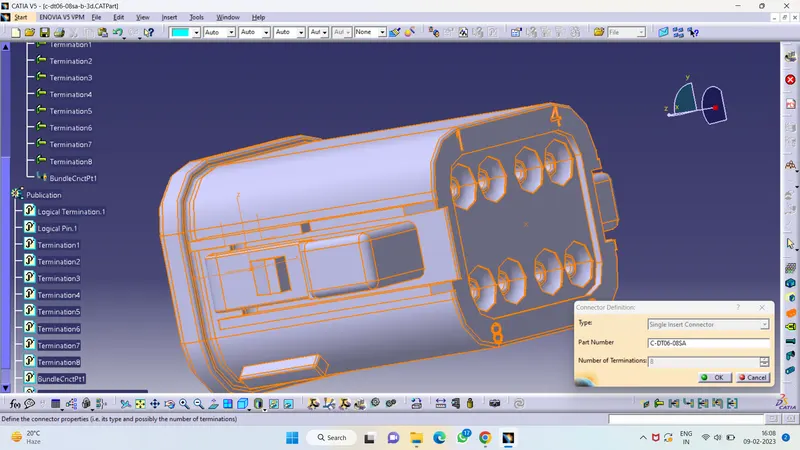
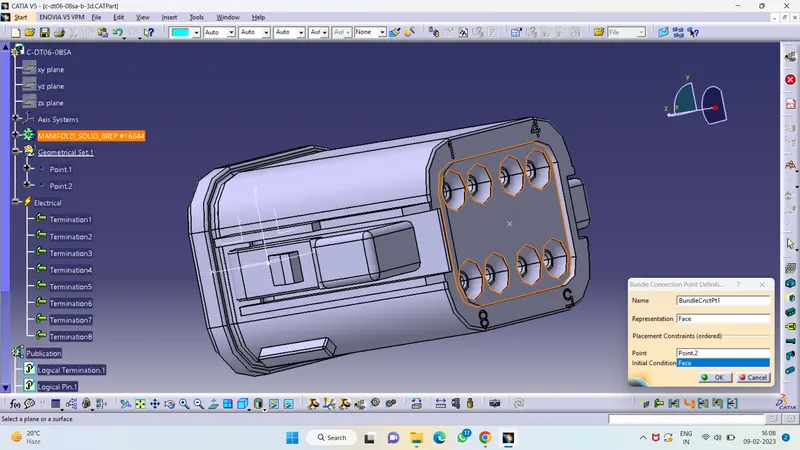
- Then using the Electrical part design we have to define the bundle and connector connection point.
Bundle Connection:
Connector Connection :
Connector:-
- First download the given CAD data.
- Define it as electical connector or cavity depending upon how the component is going to work.
- Then create a mounting point on the connector and create axis system on the point.
- Make sure that the direction of the axis system should be lie according to the conectors.
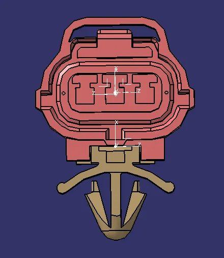
- Here X is point toward the up because the locking mechanism is in the top sides of the connector and Y should point the direction from where the bundle and mating part is going to connect. According to the X and Y we can direct the Z.
- Then using the Electrical part design we have to define the bundle and connector connection point.
Bundle Connection:
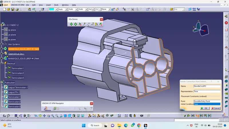
Connector Connection Point:
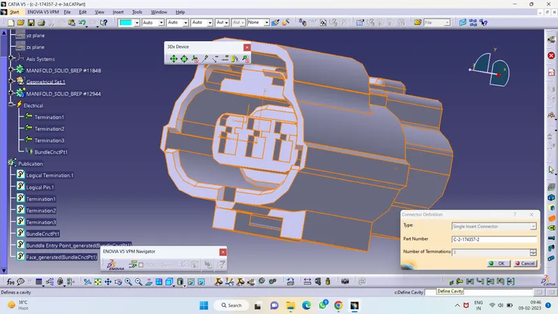
Cavity Connection Point:
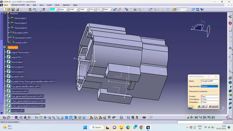
Mounting Clip:-
- For the mounting clip we have to define it as cavity.
- Then create a cavity point on the mounting and create axis system on the point.
- Make sure that the direction of the axis system should be lie according to the Connectors.
- Here X is point toward the up because the locking mechanism is in the top side of the connector and Y should point the direction from where the bundle and mating part is going to connect. According to the X and Y we can direct the Z. In the mounting we have to give the axi system like how the axis system in the connector.
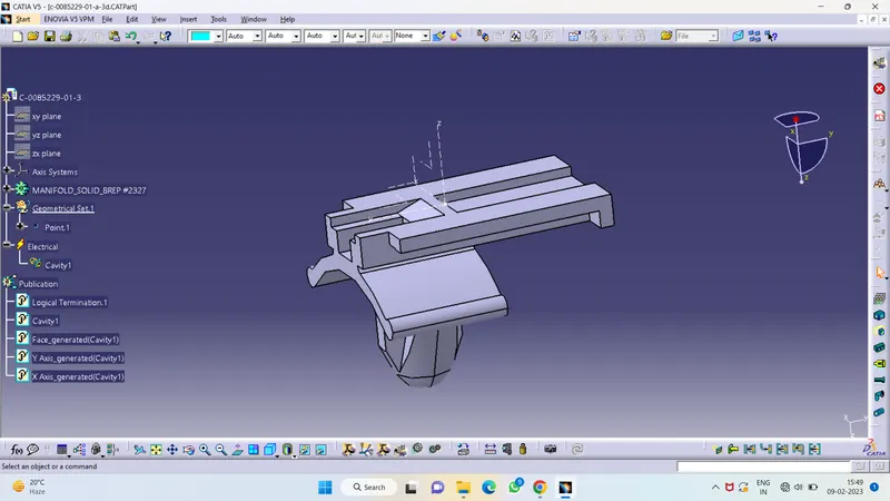
- Then using Electrical Assembly Design we have to give the constrais between the connector and mounting clip.