Wiring harness design in CATIA V5 - 3D modeling Week 2 Challenge
Wiring harness design in CATIA V5 - 3D modeling Week 2 Challenge
WIRING HARNESS DESIGN IN CATIA V5
CONNECTOR MODELING
Connector 1
Step 1:
Download the specified connector from te.com. In this part, the design workbench provides the center point and axis system to the wire inserting end and connection end. The axis must be given in a specified way:
X-axis: Towards the clamp
Y-axis: Towards the connection
Z-axis: up or down to the connector.
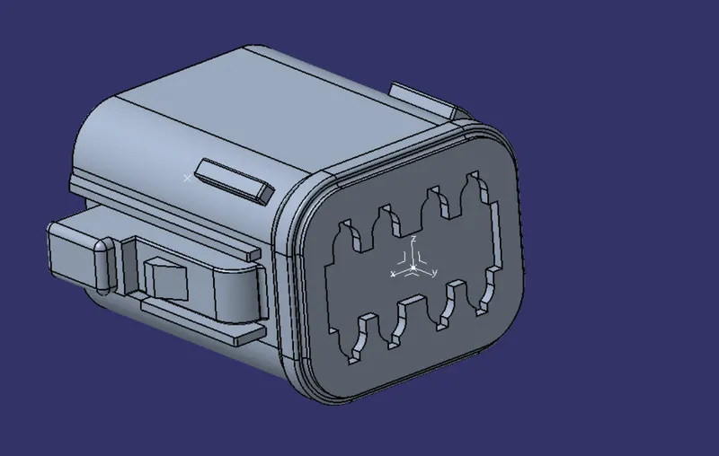
After creating Axis and Points on both the front and rear sides of the connector open the Electrical Part Design to define the Electrical properties of the connector.
Step 2:
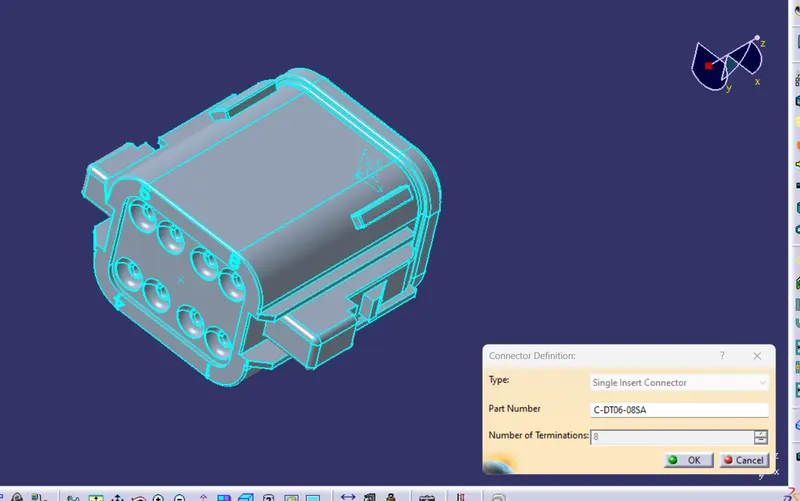
Step 3:
Define Bundle Connection Point.
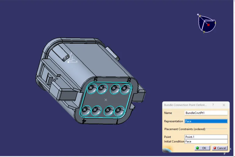
Step 4:
Define Connector Connection Point
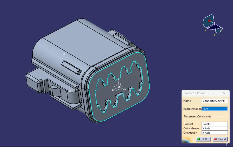
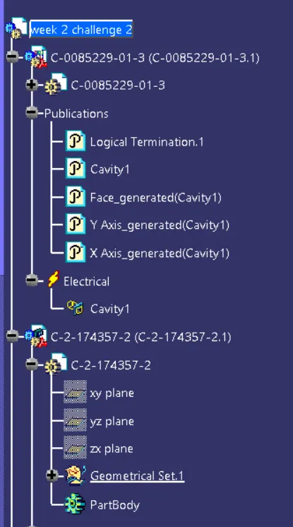
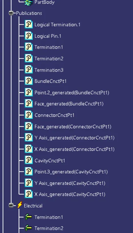
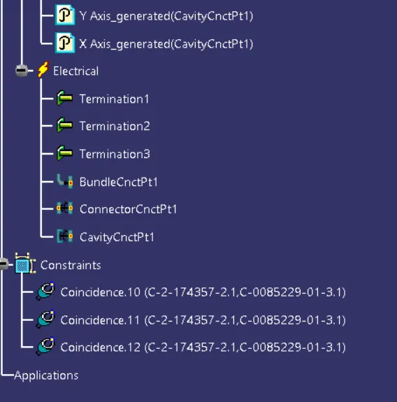
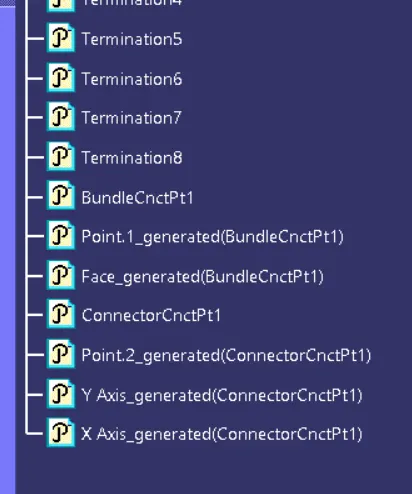
Tree Structure of Connector 1:
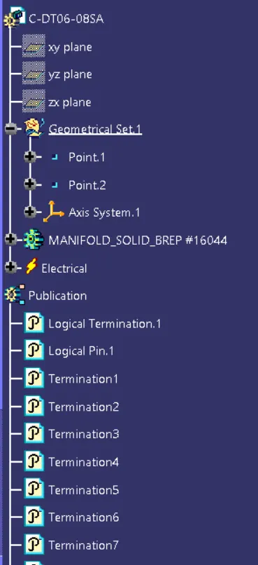
Connector 2
Step 1:
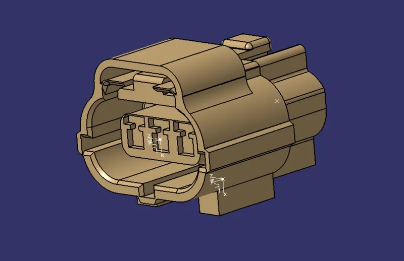
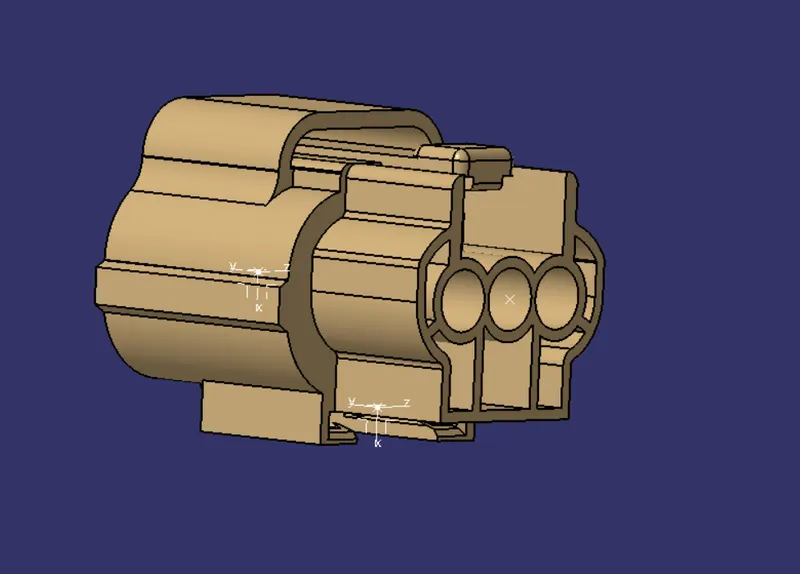
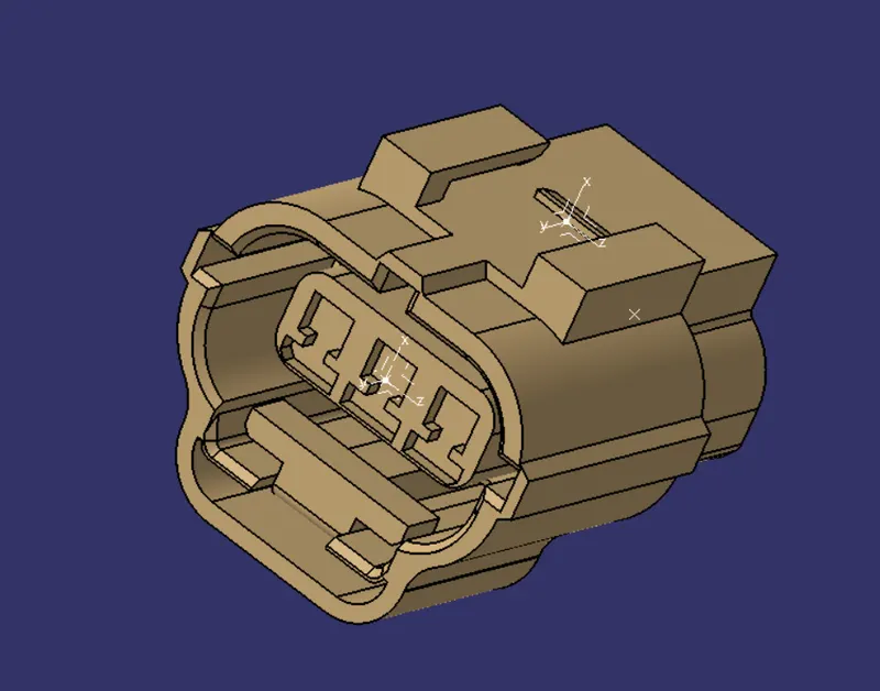
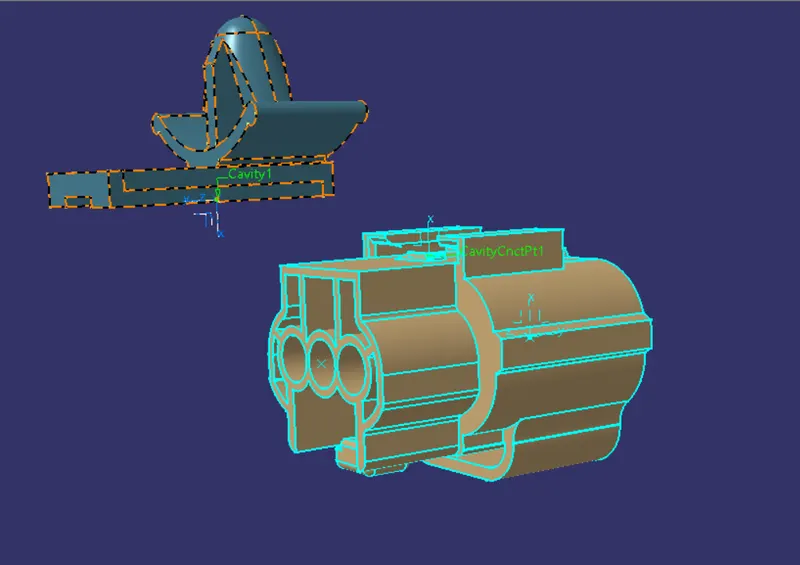
Create points on the front and rear connecting the face of the connector and on the edge connecting the mounting pin of the connector.
Create an Axis on the front point and point on the edge connecting the mounting pin.
The axis must be given in a specified way:
X-axis: Towards the clamp
Y-axis: Towards the connection
Z-axis: Left or Right sides of the connector
Step 2:
Define Connector
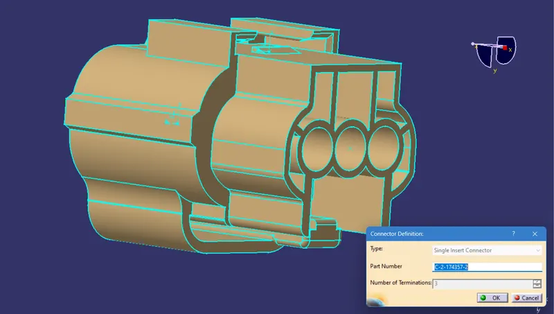
Step 3:
Define Bundle Connection Point.
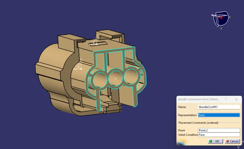
Step 4:
Define Connector Connection Point
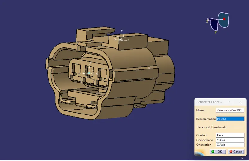
Step 5:
Define Cavity Connection Point
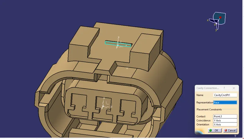
Step 6:
Save the connector in a specific folder
Step 7:
Open MOunting Clip In CATIA and create a point and an Axis on the edge connecting the connector
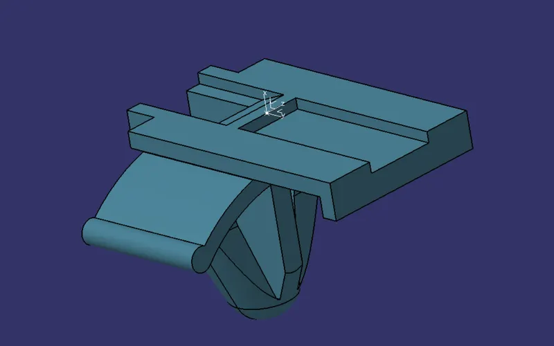
Step 8:
Define as Mounting Equipment
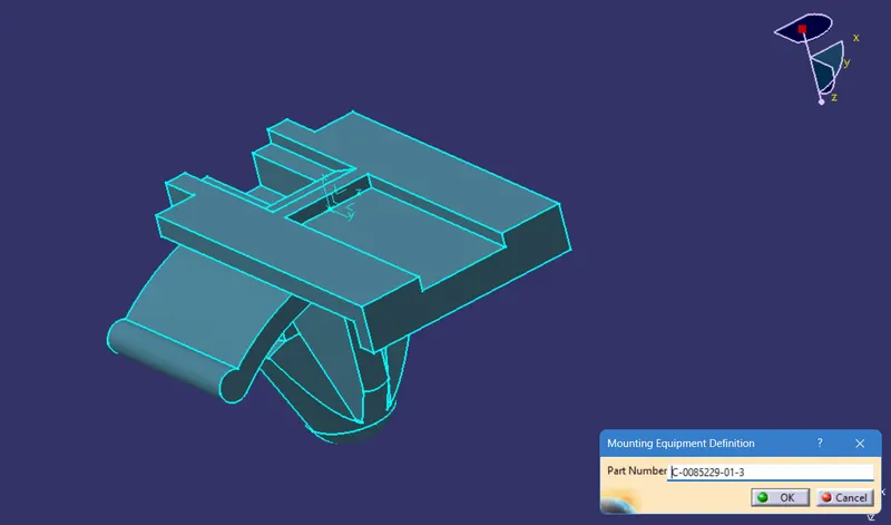
Step 9:
Define as Cavity
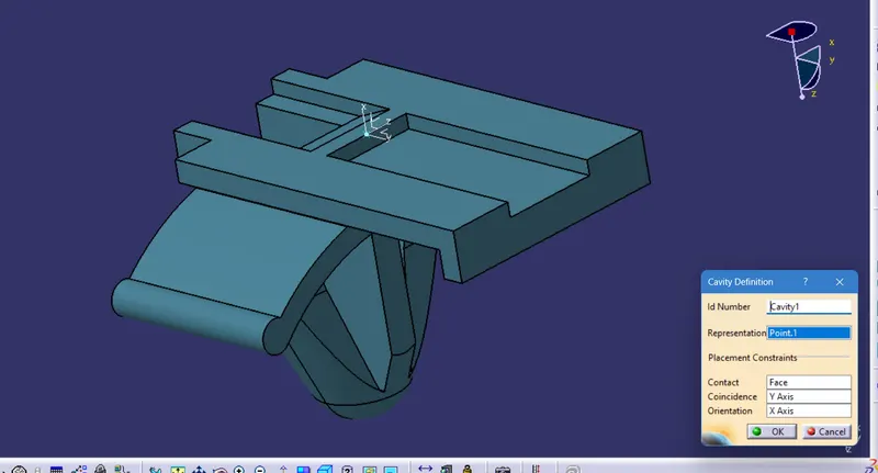
Step 10:
Save the Clip in the Specific folder
Step 11:
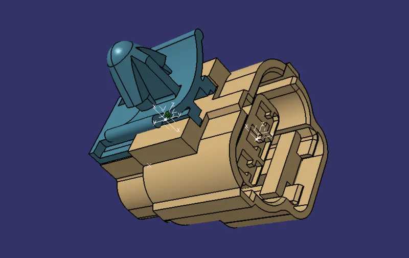
Open both the Connector and Clip in the Electrical Assembly Design
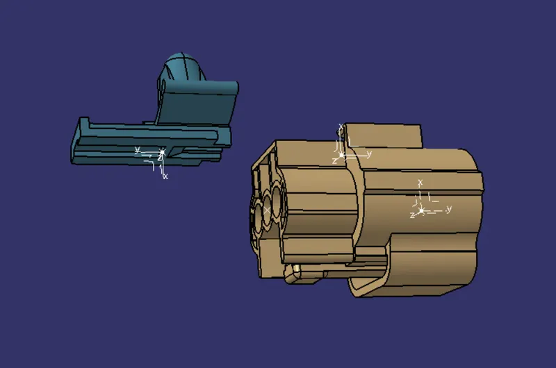
Step 12:
Use Connect Electrical Devises to join both the connector and clip
Tree Structure:-