Wiring harness design in CATIA V5 - 3D modeling Week 2 Challenge
- 1. Deutsch DT06 - 08SA
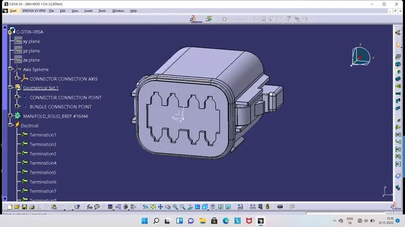
- Connector : Its Electro-Mechanical device used to connects the terminals of wire bunddle and holding the wire bunddle safely for long duration.
- For define the above shown Connector as a electrical part, we have to first download it from open source websites.
- Then we required Points, Axis at mating and mounting side of the Connector and Points at bunddle entry side of the Connector.
- So we have to first give the Points and Axis at required places on the Connector by using Part Workbench.
- Y Axis always should be normal to the desired face and X Axis should be towards the locking sides.
- Then shift to Electrical Part Workbench, now we have to click on 'Define Connector' tool.
- As we click on it, then we have to click on to the Connector, so one box will be open in screen, there we have to give the information about number of ports in the Connector.
- Here its 8 ports in this Connector.
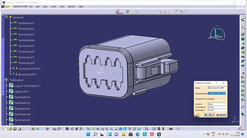
- Then we have to define the Connector Connection Point and Bunddle Entry point, if there is any mounting on Given Connector, then we have to define it also.
- So now click on to Connector Connection Point tool, so one box will be dislpay on screen as shown in above image.
- There we have to fill all the data which has been asked.
- In Name section, we can give name as per our ease, in Representation, we have to select point which we have created at mating side of the Connector.
- In Contact section, select the mating face and in Coincidence select Y Axis and in Orientation, select X Axis.
- We can see that in tree structure, Connector Connection Point added in Electrical and also all data in Publication.
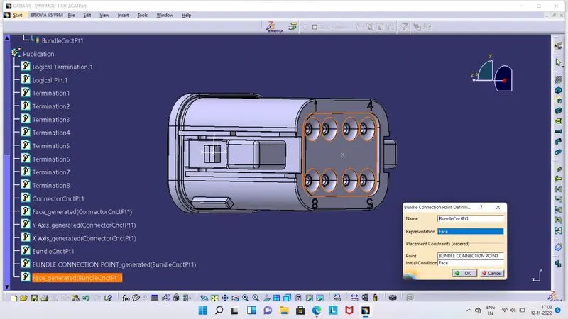
- Now we have to define Bunddle Entry Point, here end wires are connected to a respected ports of the Connectors. For that we have to click on Bunddle Connection Point tool.
- As we click on it, one box will appear on screen as shown in above image.
- Here we have fill the required data in this box.
- So we can give Name as per our ease, in Representation, we have select a face which is normal to the Connector.
- Then in Point section, we have to select a point which we had created for Bunddle Entry Point and in Initial Condition, select the face which is normal to the Connector.
- We can see that in tree structure, Bunddle Connection Point added in Electrical and also all data in Publication.
- 2. Tyco 174357-2
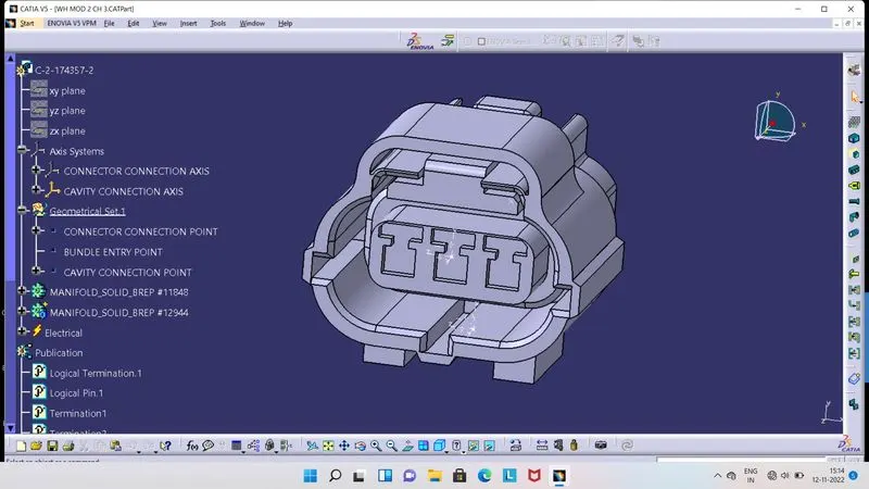
- For define the above shown Connector as a electrical part, we have to first download it from open source websites.
- Then we required Points, Axis at mating and mounting side of the Connector and Points at bunddle entry side of the Connector.
- So we have to first give the Points and Axis at required places on the Connector by using Part Workbench.
- Y Axis always should be normal to the desired face and X Axis should be towards the locking sides.
- Then shift to Electrical Part Workbench, now we have to click on 'Define Connector' tool.
- As we click on it, then we have to click on to the Connector, so one box will be open in screen, there we have to give the information about number of ports in the Connector.
- Here its 3 ports in this Connector.
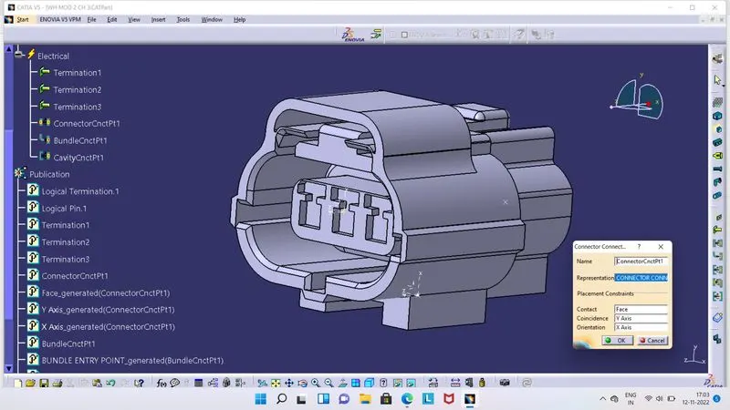
- Then we have to define the Connector Connection Point and Bunddle Entry point, if there is any mounting on Given Connector, then we have to define it also.
- So now click on to Connector Connection Point tool, so one box will be dislpay on screen as shown in above image.
- There we have to fill all the data which has been asked.
- In Name section, we can give name as per our ease, in Representation, we have to select point which we have created at mating side of the Connector.
- In Contact section, select the mating face and in Coincidence select Y Axis and in Orientation, select X Axis.
- We can see that in tree structure, Connector Connection Point added in Electrical and also all data in Publication.
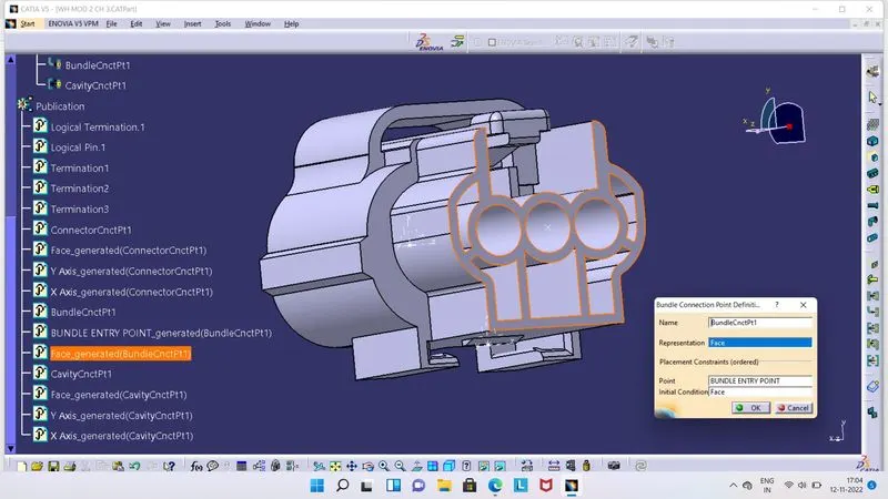
- Now we have to define Bunddle Entry Point, here end wires are connected to a respected ports of the Connectors. For that we have to click on Bunddle Connection Point tool.
- As we click on it, one box will appear on screen as shown in above image.
- Here we have fill the required data in this box.
- So we can give Name as per our ease, in Representation, we have select a face which is normal to the Connector.
- Then in Point section, we have to select a point which we had created for Bunddle Entry Point and in Initial Condition, select the face which is normal to the Connector.
- We can see that in tree structure, Bunddle Connection Point added in Electrical and also all data in Publication.
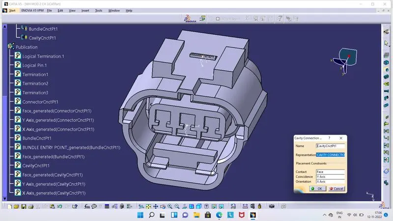
- Here in this Connector, mounting clip also available, so we have to define it by the help of created point and axis there.
- So to define Cavity Connection Point, click on the Cavity Connection Point tool, as we click on it, a box will be appear on screen as shown in above image.
- Here we have to fill required data, we can give name as per our ease and in Representation, select a point which we have created for Cavity Connection point.
- In Contact, we have to select face which will be make contact with face of of the mounting component's and in Coincidence, select Y Axis and in Orientation, X Axis.
- 3. Tyco 85229-1
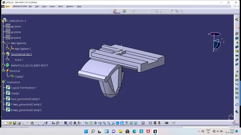
- Cavity Clip : To fixed the the connector at particular place, so wire bunddle will get more safety as connector not get moves.
- To define Cavity Clip as a electrical part, we have to first create points and axis at respected places over it in Part Workbench.
- Then shift to Electrical Part Workbench, here we have to first click on define a mounting equipment tool and then on Cavity Clip.
- So at tree structure in a Publication we can see it.
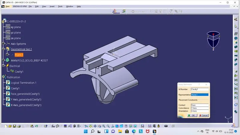
- Then we have to click on Define Cavity tool, as we click on it, a box will get appear on screen as shown in above image.
- Here we have to fill required data in this box, in representation, select the point which we had created for it in Part Workbench and in Contact, select the face which will make contact with respected face of the Connector.
- In Coincidence, select the Y Axis and in Orientation, Select X Axis.
- So at tree structure it will get apply, in Electrical and Publication, we can see that from above image, properties are add there.