Wiring harness design in CATIA V5 - 3D modeling Week 2 Challenge
REPORT
Catelogue creating
catelogue is create, click file and new then catelogue document and add family then the given name to standard catalogue and then click tool option and catelogue editior then the and the standard catlogue and ok
Then create a new catelogue file and again add family then give electrical and name is connectors. next click equipment and system then electircal mapping add the file in connector then ok.
After that add all the connectors in the electrical bench to using store device tool.
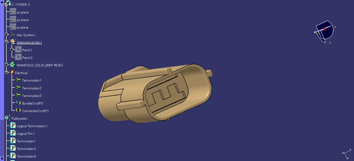
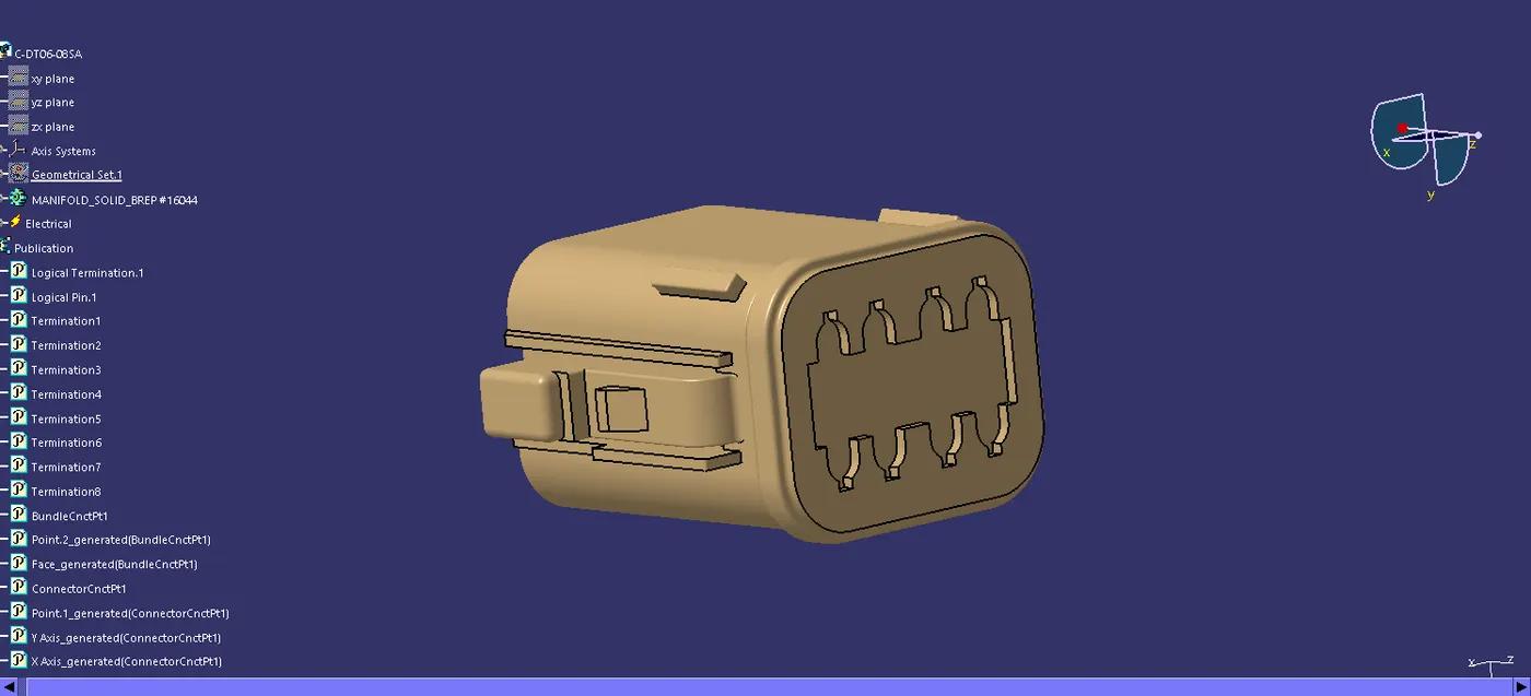
Step 1 : Import the design form the given link and then open in catia software using the using the part design work bench.
Step 2: create the point in between the two point of connector and then wire connecting side also followed the same process of the point creation
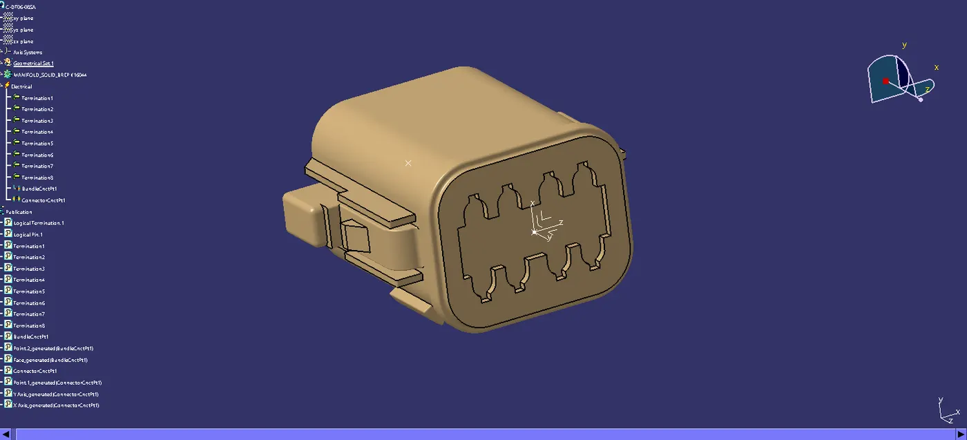
Step 3: creating the axis with the connector connecting side with thwe Y axis is coincidence direction and X axis is the oreintation.
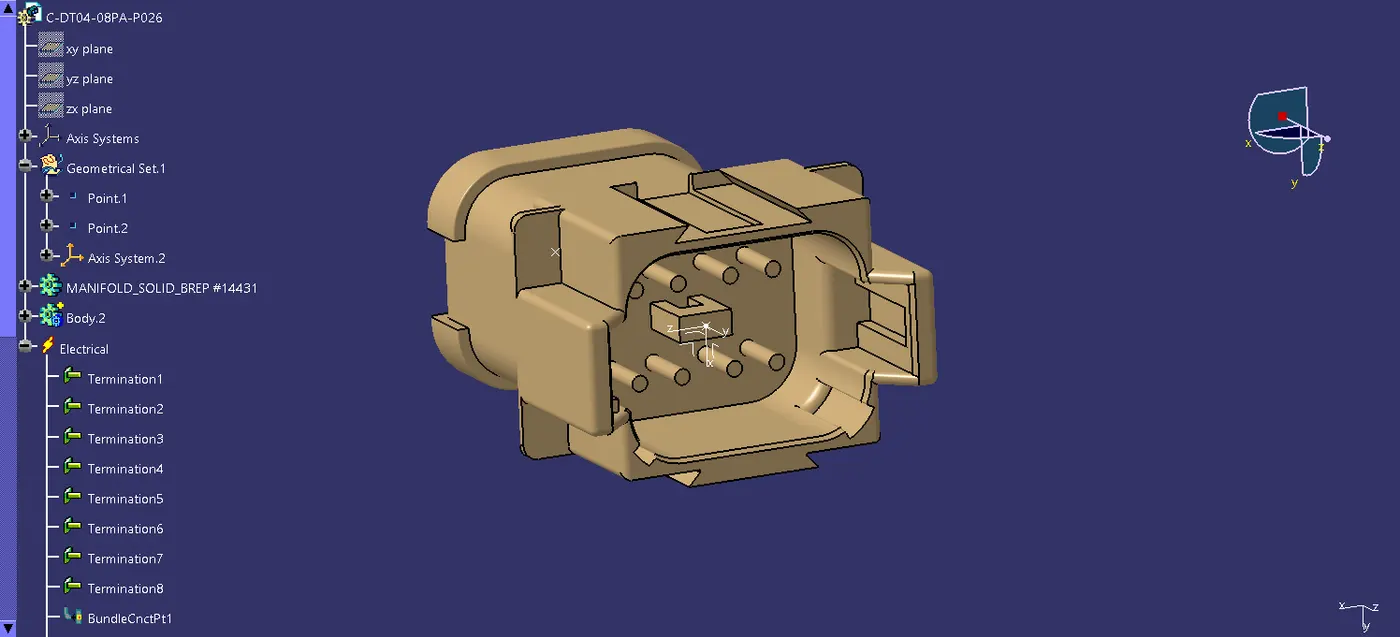
Step 4: move to the electrical part design work bench and define the connector , then define connector connection point with using the already created point.
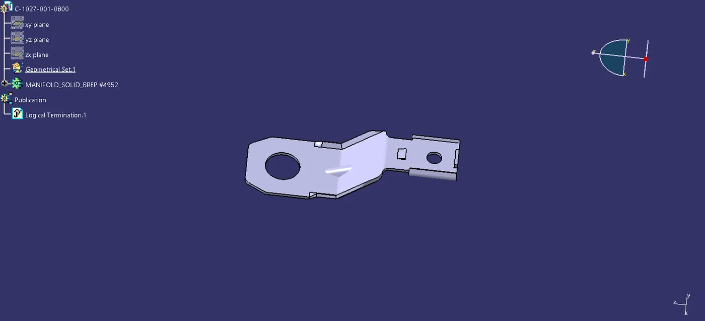
Step5: next step is the define bundle connection point with using the point and face.
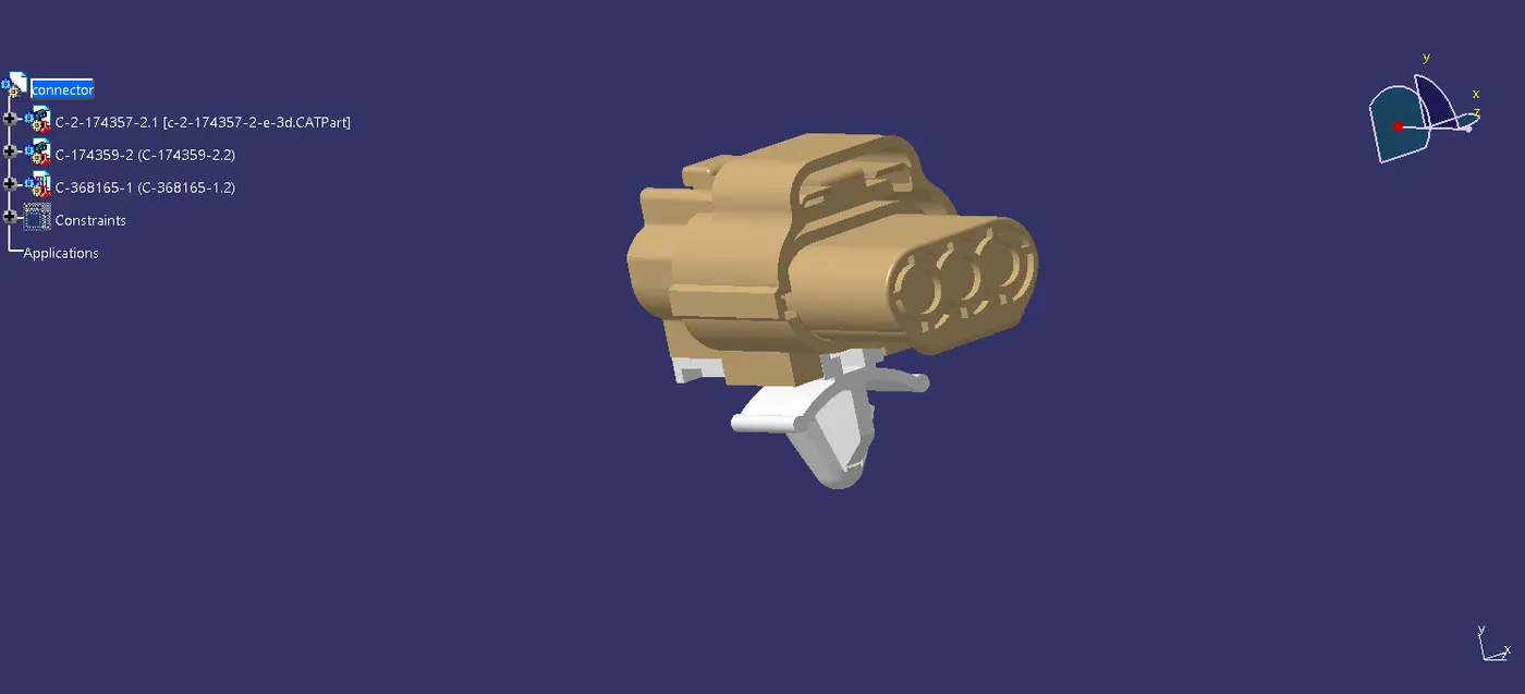
Step6: Import the part of in electrical assemble design bench then the male and female connector is the connect with the posible way of the connector.
Step7: Using the connect electrical device tool to connect the connectors and also this process is doing in part assembly bench also.
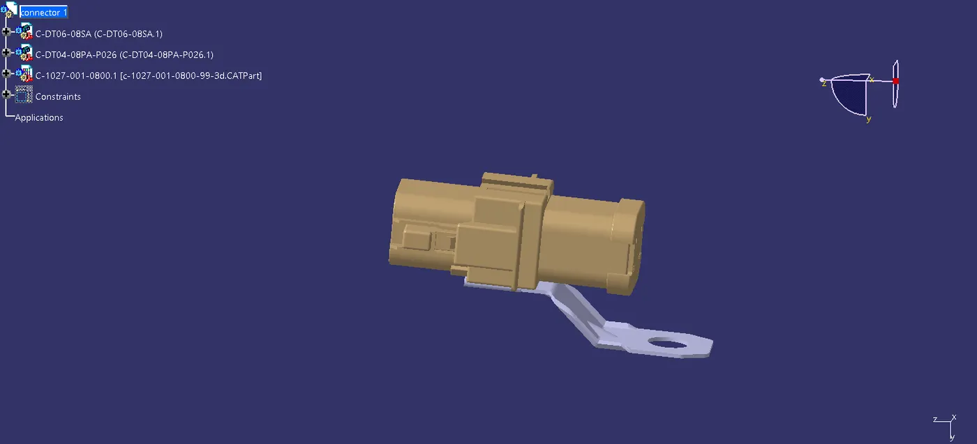
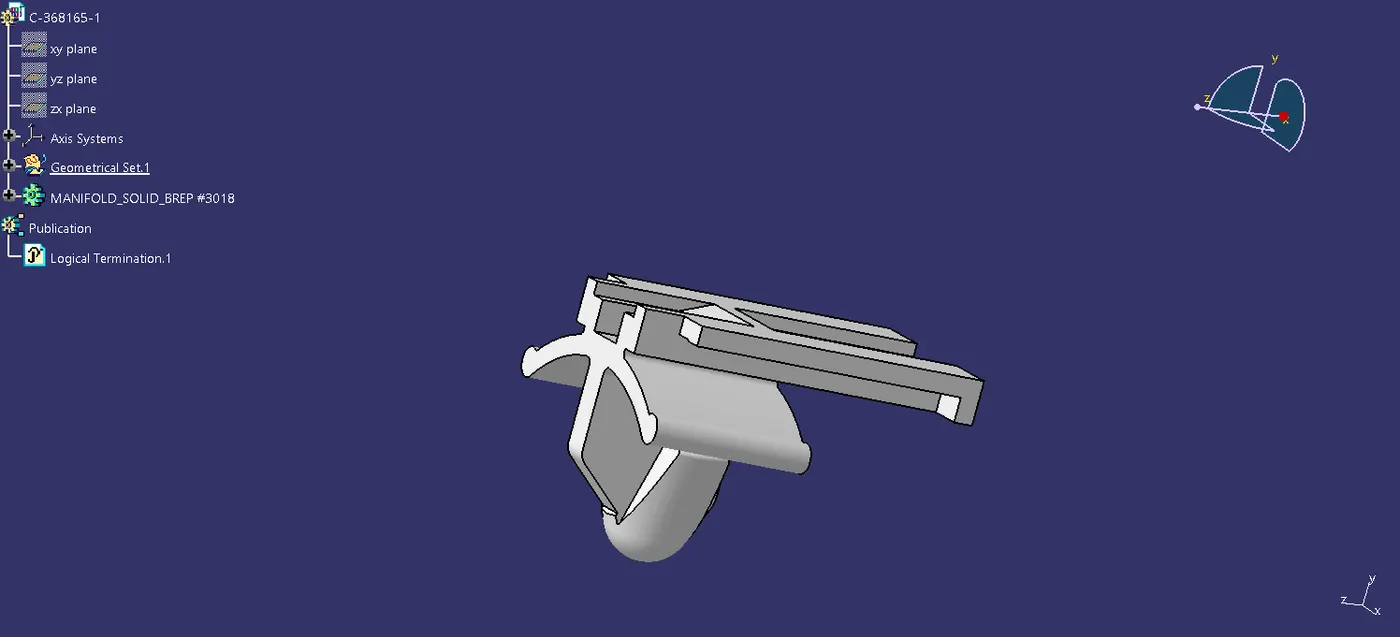
Step8: And then the connector monting plate is mounted with using the assembly bench and before that part also the defined wusing the define mounting equipment tool.
Step 9: in above used method of cammands is used in this connector also .