WELD STRENGTH CALCULATION USING EXCEL SHEET
ABSTRACT: Welding is the most common process which is widely used when two metal parts are required to be joined together for some engineering application. In some cases, the strength of the welded joints is required to be calculated. The permissible stresses for welded joints in certain structures, such as unfired pressure vessels, framework of buildings, ships or bridges, are covered by national or international codes. While designing such structures or their parts, it is obligatory on the part of the designer to use the values of permissible stresses given in the relevant standards. When the components are made of materials, such as high carbon steel or alloy steel, the weld deposit is weaker than the strength of the connected components. In such cases, the properties of weld deposit, such as tensile strength or yield strength, are considered as a criterion for determining permissible stresses.
INTRODUCTION:
Welding can be defined as a process of joining metallic parts by heating to a suitable temperature with or without the application of pressure. Welding is an economical and efficient method for obtaining a permanent joint of metallic parts. A welded joint is a permanent joint which is obtained by the fusion of the edges of the two parts to be joined together, with or without the application of pressure and a filler material. The heat required for the fusion of the material may be obtained by burning of gas (in case of gas welding) or by an electric arc (in case of electric arc welding). The latter method is extensively used because of greater speed of welding. Welding is extensively used in fabrication as an alternative method for casting or forging and as a replacement for bolted and riveted joints. It is also used as a repair medium e.g., to reunite metal at a crack, to build up a small part that has broken off such as gear tooth or to repair a worn surface such as a bearing surface.
WELDED JOINTS:
A welded joint is a permanent joint which is obtained by the fusion of the edges of the two parts to be joined together, with or without the application of pressure and a filler material. The heat required for the fusion of the material may be obtained by burning of gas (in case of gas welding) or by an electric arc (in case of electric arc welding). The latter method is extensively used because of greater speed of welding. Welding is extensively used in fabrication as an alternative method for casting or forging and as a replacement for bolted and riveted joints. It is also used as a repair medium e.g., to reunite metal at a crack, to build up a small part that has broken off such as gear tooth or to repair a worn surface such as a bearing surface.
WELDING PROCESSES:
Welding processes are broadly classified into following two groups:
- Welding processes that use heat alone to join the two parts e.g., fusion welding
- Welding processes that use a combination of heat and pressure to join the two parts e.g., forge welding
FUSION WELDING:
The welding process that uses heat alone is called ‘fusion’ welding process. In this method, the parts to be joined are held in position and molten metal is supplied to the joint. The molten metal can come either from the parts themselves called ‘parent’ metal or external filler metal is supplied to the joint. The joining surfaces of two parts become plastic or even molten under the action of heat. When the joint solidifies, the two parts fuses into a single unit. Fusion welding is further classified into following three groups:
- Thermit welding
- Gas welding
- Electric arc welding
THERMIT WELDING:
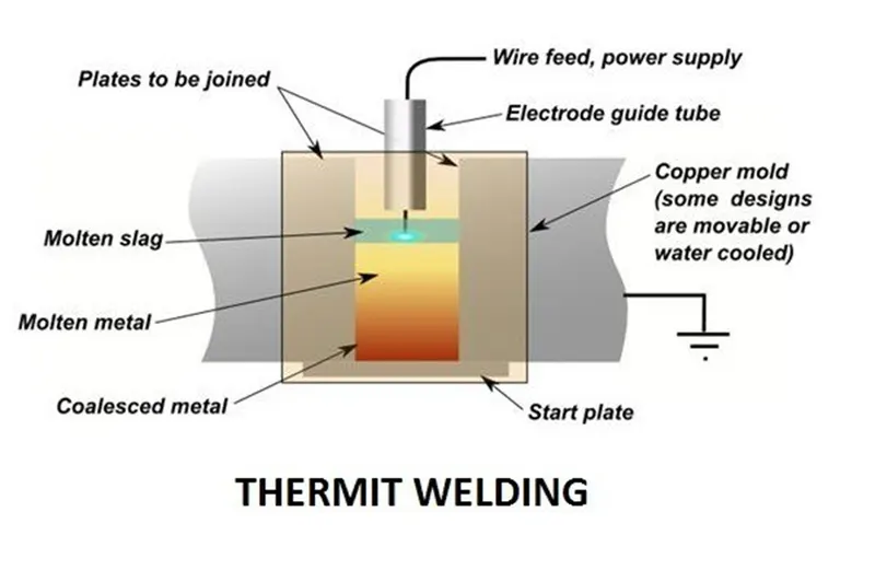
In thermit welding, a mixture of iron oxide and aluminium called thermit is ignited and the iron oxide is reduced to molten iron. The molten iron is poured into a mould made around the joint and fuses with the parts to be welded. A major advantage of the thermit welding is that all parts of weld section are molten at the same time and the weld cools almost uniformly. This results in a minimum problem with residual stresses. It is fundamentally a melting and casting process. The thermit welding is often used in joining iron and steel parts that are too large to be manufactured in one piece, such as rails, truck frames, locomotive frames, other large sections used on steam and rail roads, for stern frames, rudder frames etc. In steel mills, thermit electric welding is employed to replace broken gear teeth, to weld new necks on rolls and pinions, and to repair broken shears.
GAS WELDING:
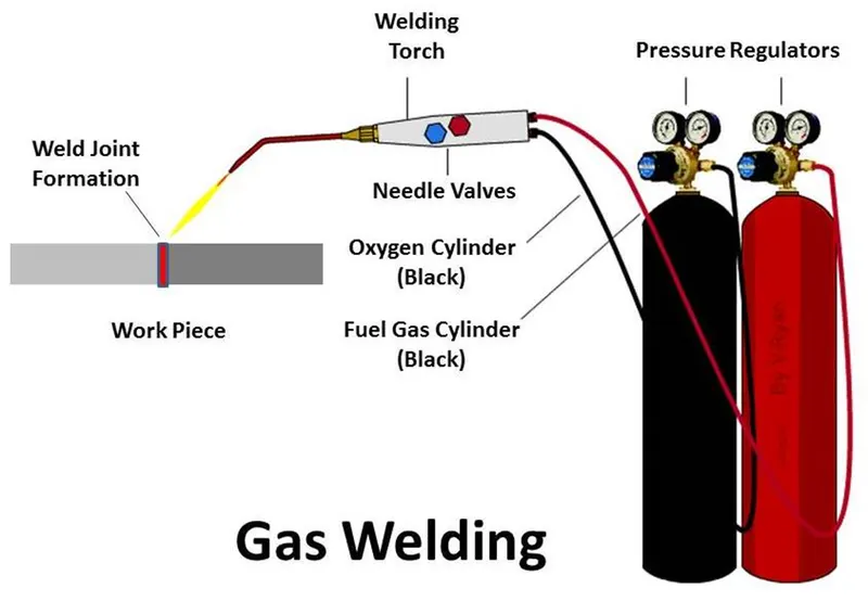
In gas welding process, oxygen-hydrogen or oxygen-acetylene gas is burned in a torch to create a pointed flame. This flame is directed upon the surfaces to be joined. The intense heat of the flame heats the adjoining parts of the joint to fusion temperature and simultaneously melts the welding rod to supply the molten metal to the joint. A flux is used to remove the slag. There is a basic difference between gas welding and electric arc welding. In gas welding, the rate of heating is slow compared with electric arc welding. Therefore, the operator has more control over both heating and cooling rates. The gas welding is preferred for joining thin parts due to low rate of heating.
Electric Arc Welding:
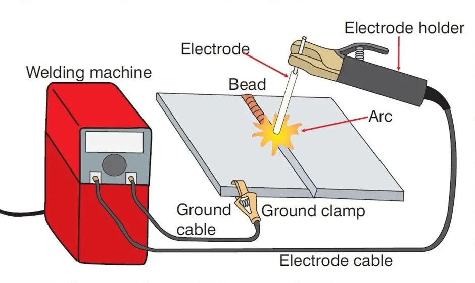
In electric arc welding, the work is prepared in the same manner as for gas welding. In this case the filler metal is supplied by metal welding electrode. The operator, with his eyes and face protected, strikes an arc by touching the work of base metal with the electrode. The base metal in the path of the arc stream is melted, forming a pool of molten metal, which seems to be forced out of the pool by the blast from the arc. A small depression is formed in the base metal and the Molten pool molten metal is deposited around the edge of this Slag depression, which is called the arc crater. The slag is brushed off after the joint has cooled. The arc welding does not require the metal to be preheated and since the temperature of the arc is quite high, therefore the fusion of the metal is almost instantaneous.
There are two kinds of arc welding depending upon the type of electrode.
- Un-shielded arc welding
- Shielded electric arc welding
Welding processes that use a combination of heat and pressure to join the two parts are classified into following two groups:
- Forge welding
- Electric resistance welding
FORGE WELDING:
In forge welding, the parts are heated to reach the plastic stage and the joint is prepared by impact force. The impact force is produced either by a hand hammer or a press. Wrought iron or low carbon steel can be forge welded. This process has limited use in present time. It is used in fabrication of wrought iron pipes.
ELECTRIC RESISTANCE WELDING:
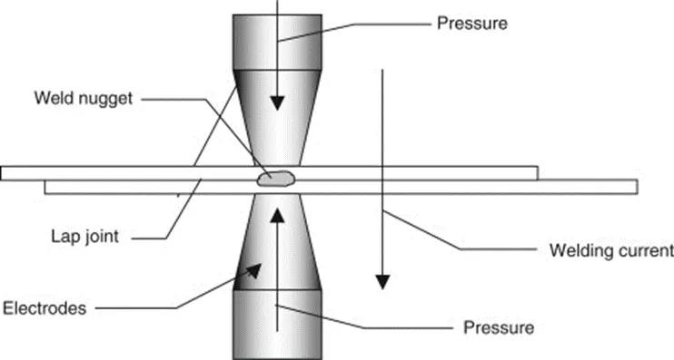
In electric resistance welding, the parts to be connected are clamped together and a high amperage electric current is passed from one part to other. Resistance of metallic parts to electric current creates heat. This heat is utilized for melting the adjoining parts. No filler material is used in this process. There are two terms related to electric resistance welding viz. spot welding and seam welding. When a lap joint is formed by applying pressure by two electrodes, one on each side of overlapped plates, a 'spot' weld is produced. If two rollers are substituted for the point electrodes and the plates are pulled between the rollers, a ‘seam’ weld is produced. Electric resistance welding can be easily automated and is often used as mass production technique. Therefore, it is commonly used in automobile industries.
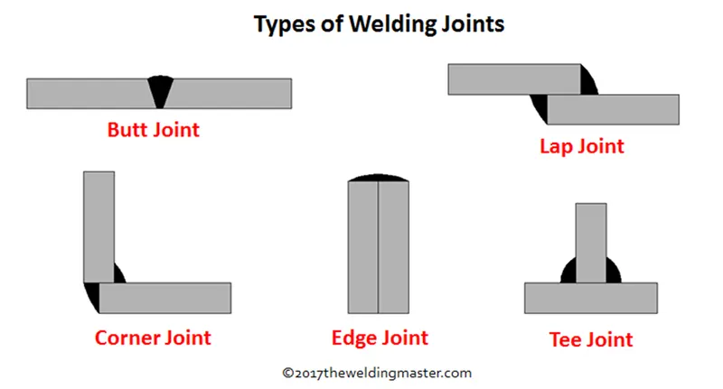
TYPES OF WELDED JOINTS:
- Lap joint or Fillet joint
- Butt joint
- Corner joint
- Edge joint
- T-joint
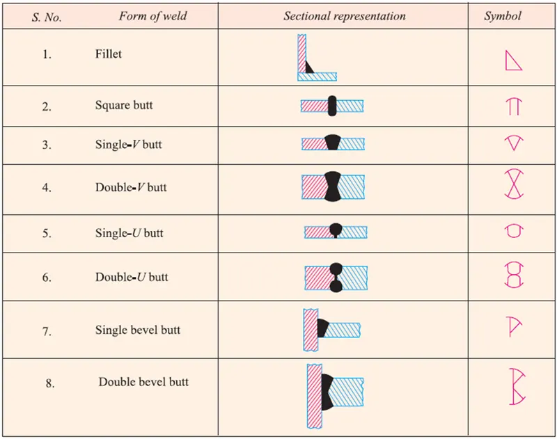
WELD SYMBOLS:
BUTT JOINTS:
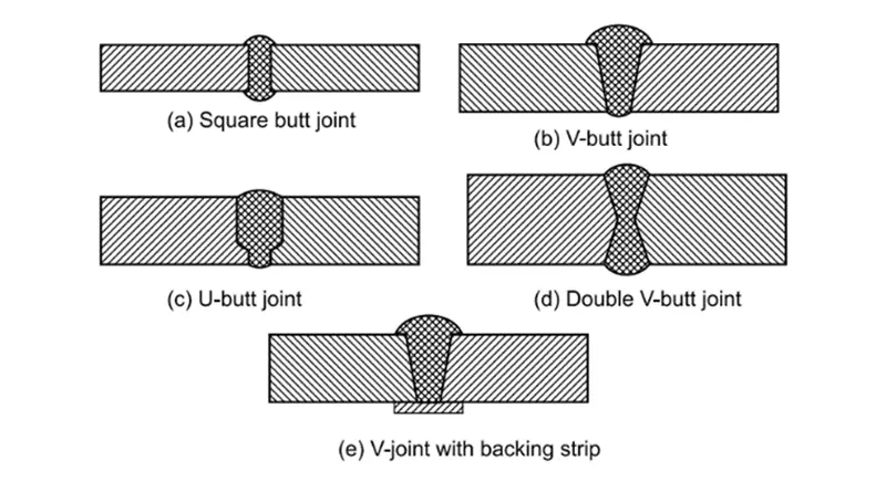
Welded joints are divided into two groups-butt joint and fillet joints. A butt joint can be defined as a joint between two components lying approximately in the same plane. Butt joint connects the ends of the two plates. The selection of the types of butt joint depends upon the plate thickness and the reliability. Some guidelines are as follows:
- When the thickness of the plates is less than 5 mm, it is not necessary to bevel the edges of the plates. There is no preparation of the edges of the plates before welding. The edges are square with respect to the plates. Therefore, the joint is called square butt joint.
- When the thickness of the plates is between 5 to 25 mm, the edges are bevelled before welding operation. The edges of two plates form V shape. Therefore, the joint is called V-joint or single welded V-joint. This joint is welded only from one side.
- When the thickness of the plates is more than 20 mm, the edges of the two plates are machined to form U shape. The joint is welded only from one side. It is called single welded U-joint.
- When the thickness of the plates is more than 30 mm, a double welded V-joint is used. The joint is welded from both sides of the plate.
When the welding is to be done only from one side, a single welded V-joint with backing strip is used to avoid the leakage of the molten metal on the other side. There are two types of the backing strip-permanent steel backing and removable copper backing. In applications like pressure vessels, the reliability of the joint is important consideration. Single welded V-joint is more reliable than square butt joint. Single welded V-joint with backing strip is more reliable than single welded V-joint without backing strip. Double welded V-joint is more reliable than single welded V-joint with backing strip. The cost also increases with the reliability of the joint.
FILLET JOINTS:
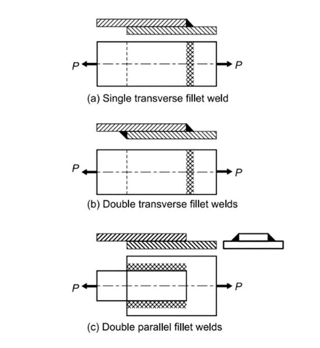
Fillet joint, also called lap joint, is a joint between two overlapping plates or components. A fillet weld consists of an approximately triangular cross-section joining two surfaces at right angles to each other. There are two types of fillet joint-transverse and parallel. A fillet weld is called transverse, if the direction of weld is perpendicular to the direction of the force acting on the joint. Single transverse fillet joint is not preferred because the edge of the plate, which is not welded, can warp out of shape. In Fig (a), the edge of the lower plate is free to deflect. Therefore, a double transverse fillet weld, as shown in Fig (b), is preferred. A fillet weld is called parallel or longitudinal, if the direction of weld is parallel to the direction of the force acting on the joint.
There are two types of cross-sections for fillet weld-normal and convex, as shown in Fig. The normal weld consists of an isosceles triangle – a triangle having two equal sides. It is shown in Fig (a). A convex weld is shown in Fig (b).
Convex weld requires more filler material and more labour. There is more stress concentration in convex weld compared with triangular weld. Therefore, normal weld is preferred over convex weld.
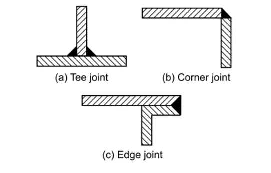
In addition to butt and fillet joints, there are some other types of welded joints, which are shown in Fig. 8.4. A tee-joint is a joint between two components located at right angles to each other in the form of a T. In this case, the end face of one component is welded to the side of the other component by means of a fillet weld as shown in Fig. 8.4(a). A corner joint is a joint between two components, which are at right angles to each other in the form of an angle. The adjacent edges are joined by means of fillet weld as shown in Fig. 8.4(b). An edge joint is a joint between the edges of two or more parallel components as shown in Fig. 8.4(c). It is used for thin plates subjected to light loads.
STRENGTH OF BUTT WELDS
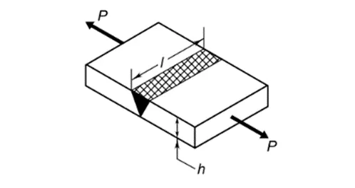
A butt welded joint, subjected to tensile force P, is shown in Fig. The average tensile stress in the weld is given by,
σt = P/hl (1)
where, σt = tensile stress in the weld (N/mm2)
P= tensile force on the plates (N)
h = throat of the butt weld (mm)
l = length of the weld (mm)
The throat of the weld does not include the bulge or reinforcement. The reinforcement is provided to compensate for flaws in the weld. Equating the throat of the weld ‘h’ to the plate thickness ‘t’ in Eq. (1), the strength equation of butt joint can be written as,
P= σt tl
where, P = tensile force on plates(N)
σt = permissible tensile stress for the weld (N/mm2)
t = thickness of the plate (mm)
STRENGTH OF PARALLEL FILLET WELDS
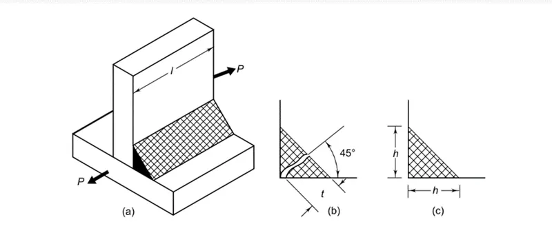
A parallel fillet weld subjected to a tensile force P is shown in Fig.(a). The enlarged view of the fillet weld is shown in (c). There are two terms related to the dimensions of the fillet weld, viz., leg h and throat t. The size of the weld is specified by the leg length. The cross-section of the fillet weld consists of a right-angled triangle having two equal sides. The length of each of the two equal sides is called a leg. As a rule, the leg length h is equal to the plate thickness. The throat is the minimum cross-section of the weld located at 45° to the leg dimension. Therefore,
t = h cos (45°)
or
t = 0.707 h (1)
Failure of the fillet weld occurs due to shear along the minimum cross-section at the throat. It will be proved at a later stage that for parallel fillet weld, the inclination of the plane where maximum shear stress is induced, is 45° to the leg dimension. The shear failure of the weld is shown in Fig.(b). The cross-sectional area at the throat is (tl) or (0.707 hl). The shear stress in the fillet weld is given by,
τ = P/0 707hl (2)
Rearranging the terms of Eq. (2), the strength equation of the parallel fillet weld is written in the following form,
P = 0.707 hlτ (3)
Where,
P = Tensile force on plates (N)
h = leg of the weld (mm)
l = length of the weld (mm)
τ = permissible shear stress for the weld (N/mm2)
Usually, there are two welds of equal length on two sides of the vertical plate. In that case,
P = 2 (0.707 hlτ)
or
P = 1.414 hlτ (4)
In determining the required length of the weld,15 mm should be added to the length of each weld calculated by Eqs. (3) and (4) to allow for starting and stopping of the weld run. In case of a static load, the permissible shear stress for the fillet welds is taken as 94 N/mm2 as per the code of American Welding Society (AWS).
STRENGTH OF TRANSVERSE FILLET WELDS
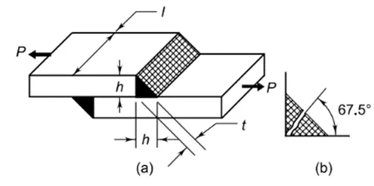
A transverse fillet weld subjected to a tensile force P is shown in Fig.(a). The transverse fillet welds are subjected to tensile stress. The minimum cross-section of the weld is at the throat. Therefore, the failure due to tensile stress will occur at the throat section. The cross-sectional area at the throat is (tl). The tensile stress in the transverse fillet weld is given by,
σt = P/tl (1)
Substituting Eq. (t=h cos (45°)) in the above equation,
σt = P/0.707hl (2)
Rearranging the terms of Eq. (2), the strength equation of the transverse fillet weld is written in the following form,
P = 0.707 hlσt (3)
where,
σt = permissible tensile stress for the weld (N/mm2)
Usually, there are two welds of equal length on two sides of the plate as shown in Fig.(a). In such cases,
P = 2 (0.707 hlσt)
or
P = 1.414 hlσt (4)
The nature of stresses in the cross-section of the transverse fillet weld is complex. The weld is subjected to normal stress as well as shear stress. In addition, the throat is subjected to bending moment, which adds to the complications. Theoretically, it can be proved that for transverse fillet weld, the inclination of the plane, where maximum shear stress is induced, is 67.5° to the leg dimension as shown in Fig. (b). In order to simplify the design of fillet welds, many times shear failure is used as the failure criterion. It is assumed that the stress in the transverse fillet weld is shear stress on the throat area for any direction of applied load. With this assumption, Eqs (3) and (4) derived for parallel fillet welds are also used for the transverse fillet welds.
FORMULAS USED:
STRENGTH OF SINGLE BUTT WELD
P= σt tl
STRENGTH OF DOUBLE BUTT WELD
P= (t1+t2) σtl
STRENGTH OF SINGLE PARALLEL FILLET WELD
P = 0.707 hlτ
STRENGTH OF DOUBLE PARALLEL FILLET WELD
P = 1.414 hlτ
STRENGTH OF SINGLE TRANSVERSE FILLET WELDS
P = 0.707 hlσt
STRENGTH OF DOUBLE TRANSVERSE FILLET WELDS
P = 1.414 hlσt
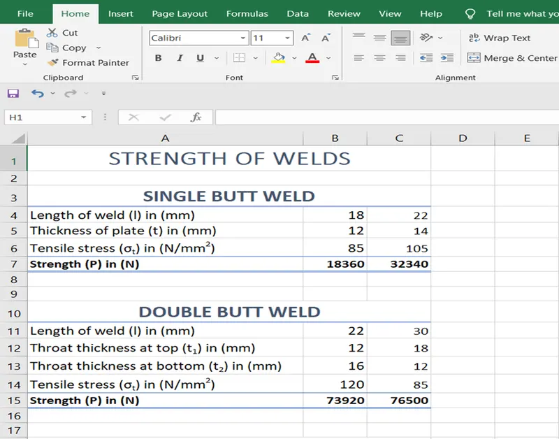
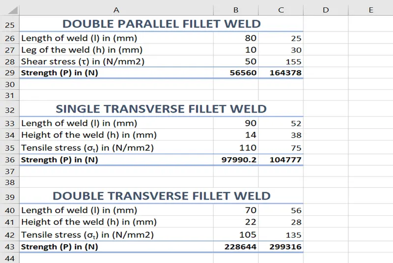
EXCEL SHEET:
PROCEDURE TO CALCULATE WELD STRENGTH USING EXCEL:
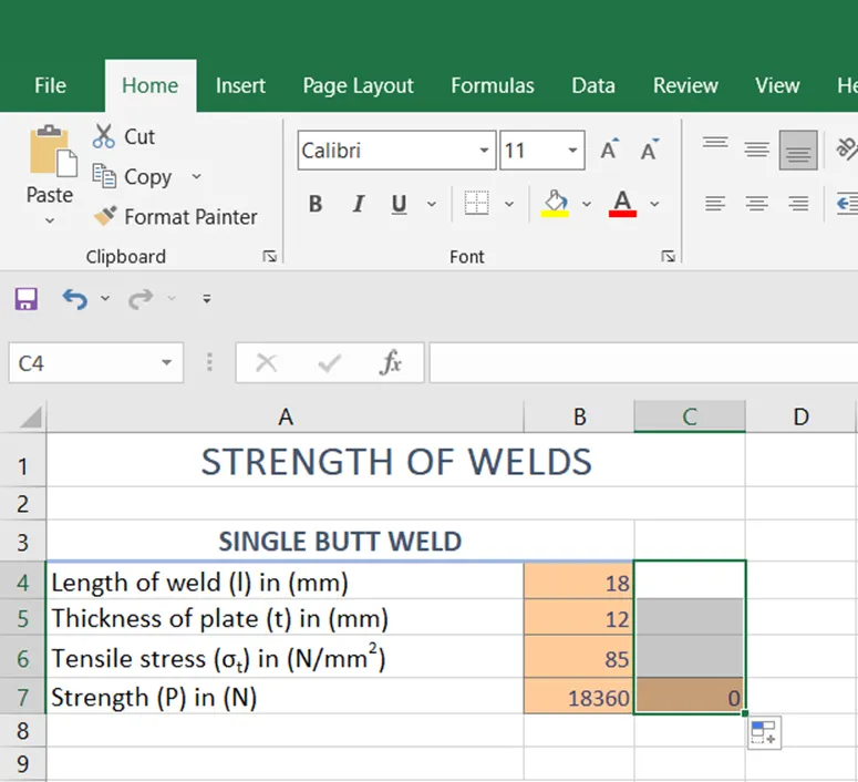
- Select the type of weld
- Enter the length of weld (l)
- Enter in the size of weld (t)
- Input the permissible tensile stress σt or the permissible shear stress τ for the weld
- Press enter and we would get the value for the weld strength (P) of the joint
CONCLUSION:
By working on this project, I have gained complete knowledge about welding and the different types of welding processes, the various weld joins which are used to join two metal components together. It helped me to understand the concept of weld strength and the formulas required to calculate the weld strength for different types of weld joints. With the reference of these formulas a weld strength calculator tool was created in excel. By giving the input values like length, throat value, tensile strength, etc in excel the correct weld strength value was obtained. It was observed that the weld strength (P) readings obtained for all types of weld joints were correct.
REFERENCES:
[1] Bhandari, V. B. Design of machine elements. Tata McGraw-Hill Education, 2010.
[2] Khurmi, R. S., and J. K. Gupta. A textbook of machine design. S. Chand publishing, 2005.
[3] Patil, S. R., and C. A. Waghmare. "Optimization of MIG welding parameters for improving strength of welded joints." Int. J. Adv. Engg. Res. Studies/II/IV/July-Sept 14 (2013): 16.
[4] Anami, Kengo, and Chitoshi Miki. "Fatigue strength of welded joints made of high‐strength steels." Progress in Structural Engineering and Materials 3.1 (2001): 86-94.
[5] https://www.omnicalculator.com/construction/welding