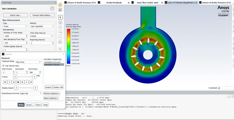
Week 9- Unsteady moving zones Approach
AIM:
To Simulate the motion of blades in a generic turbomachinery component using an unsteady approach.
Solution procedure:
Here there is three domains and two interfaces
Zone 1 = Inlet
Zone 2 = Rotating blades
Zone 3 = Outlet of the turbomachinery
Inorder to transfer data between these zones, interfaces must be defined between zone 1 and zone 2, and Zone 2 and 3.
Solver settings:
Zones >> Append >> Append case file
and click on domain2.msh
and click on display to see the domain 2 which is rotating frame.
Simulation is run at no load boundary conditions.
ie, inlet and outlet is set at ambient conditions. So here flow happens only due to the rotation of the frame
Mesh interfaces >> Create the mesh interface
Uncheck pseudo transient and change Courant number to 10
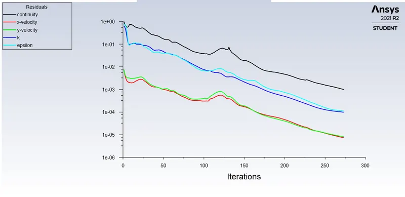
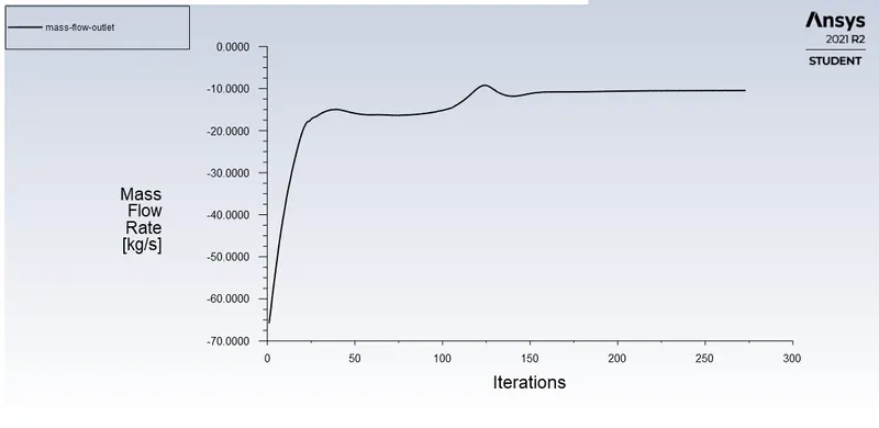
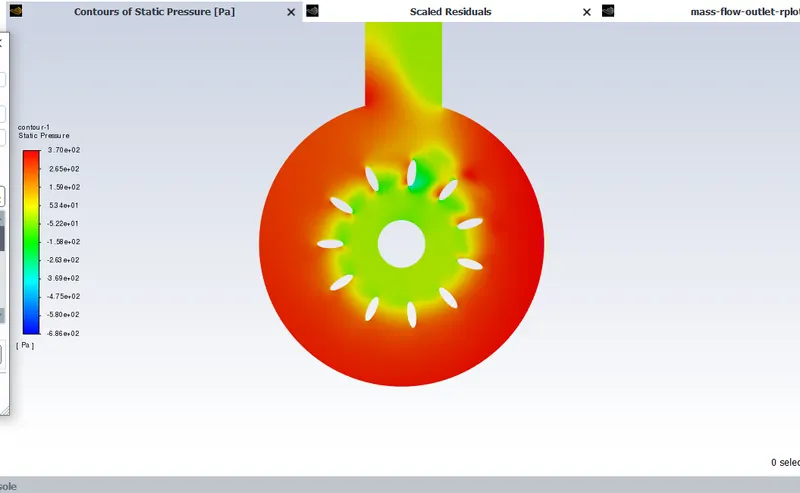
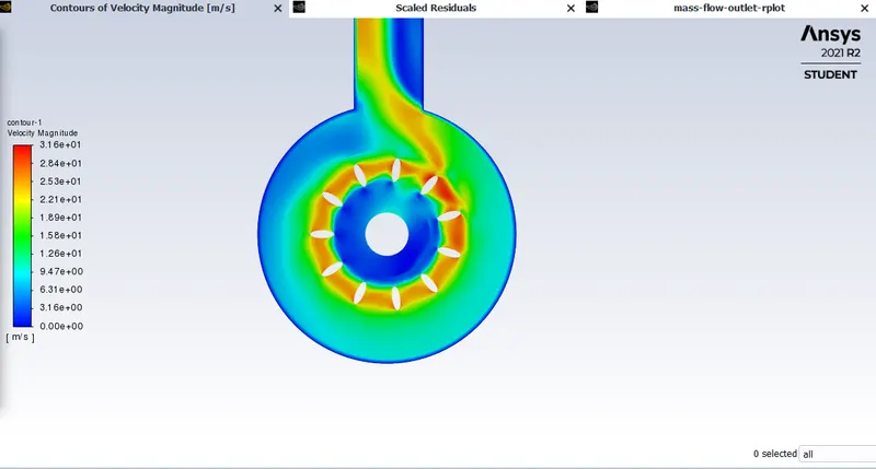
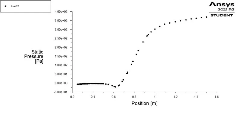
In the static pressure contour shown below:
we can see that as the domain rotates low static pressure is created at the inlet
and high static pressure is created at the outer domain.
Transient analysis
Enable mesh motion for the rotating frame.
Specify 300rpm
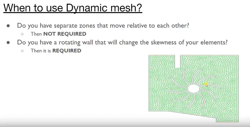
Mesh motion is used when for cases similar to that shown in the below image,
where the rotating wall will effect the skewness o fmesh elements near the wall
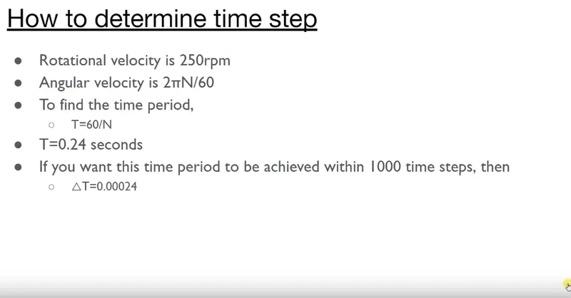
for our case N= 300rpm
T=60/N = 60/300 = 0.2seconds
and time step size, dT=0.0002
- Pressure animation: https://youtu.be/Vr9f2oUcf50
- Velocity animation: https://youtu.be/nCmps7fHfB8