Week 9- Unsteady moving zones Approach
Aim :
To simulate the given turbomachine model using moving zone approach.
Objective :
To obtain velocity and pressure plots for the given model using moving reference frame and moving mesh approaches. And compare the results.
Procedure :
The given mesh geomentry model is imported to the fluent setup, since the entire model is made up of different mesh frames/zones we combine diffrent mesh files using the option "Append" and create a single model. The imported mesh is then used to know the different boundary regions and the interfaces. We choose the k-`epsilon` realizable model to solve,as this model proven best for internal flow and rotating macheinaries.
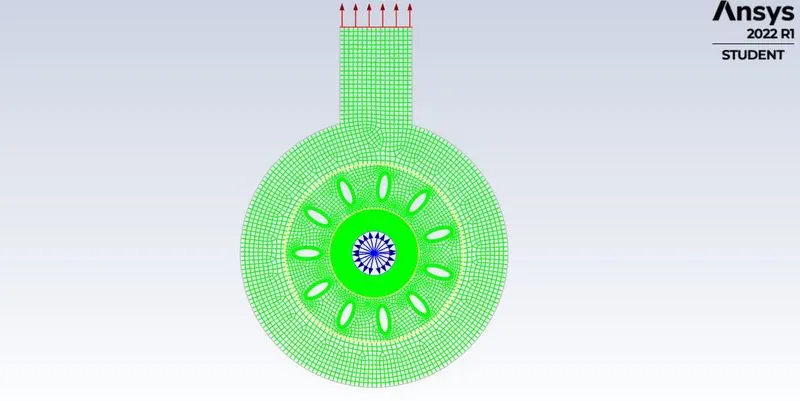
Then for cell zone condition we do it as two cases,
Case 1 - Moving Reference Frame Approach
Case 2 - Moving Mesh Approach
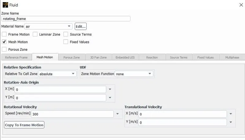
Under cell zone we choose the rotating frame as the moving zone and for case 1 we mention it as the frame motion and for case 2 we choose the mesh motion condition and give the rotational velocity as 300 rpm.
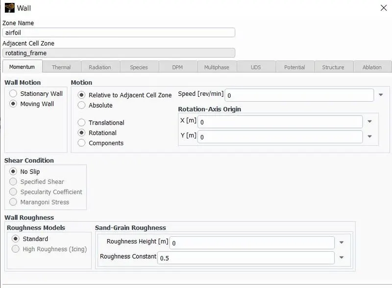
For the boundary condition we mention airfoil/blade as wall. And Since we want the airfoil to be moving we mention it as moving wall and rotational wall, Since for Case 1 it is MRF we mention the airfoil as movement with relative to adjecent cell zone.
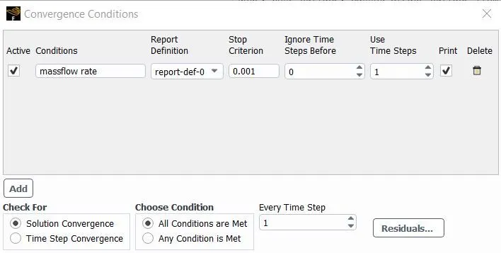
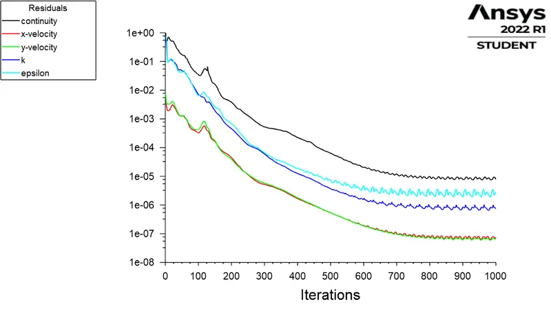
For the convergence condition we introduce the mass flow rate to achive convergence.
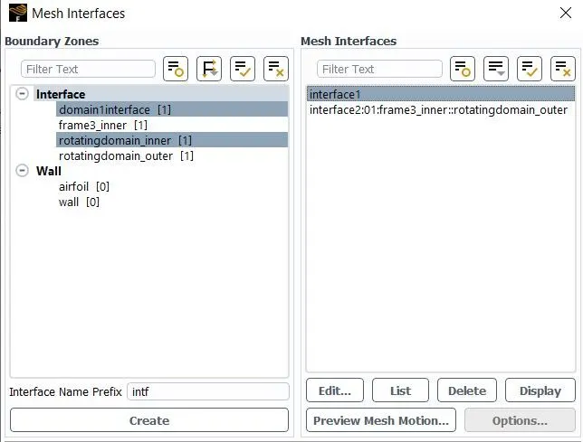
We have to have a interface region so thet the information between adjecent frames/region is transfered to have a better result. For this reason we identify the overlaping boundaries within the model and couple the adjecent boundaries.
`omega =(2pi N)/60`
`(2pi)/T = (2pi N)/60`
`T = 60/N`
N = 300 rpm
T = 0.2
For the no.of timesteps of 1000 , Time step size `Delta`t = 0.0002
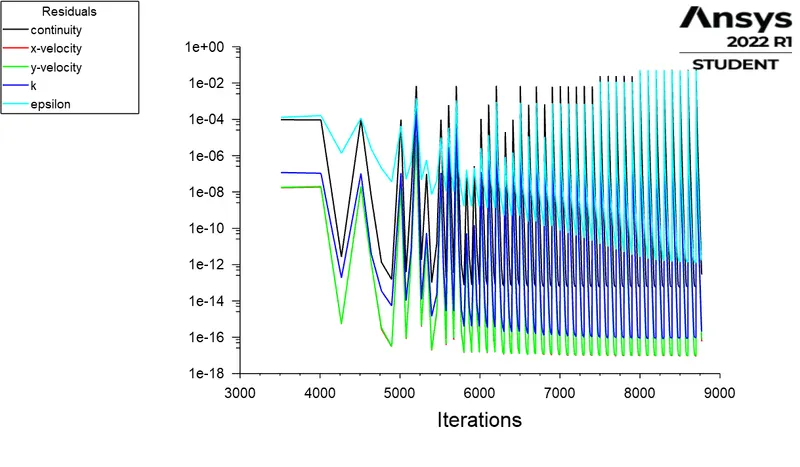
We ran the simutalion for 1000 iterations, for transient mesh condition we gave the time step size as 0.0002.
Result :
Case 1 -
Resuidal -
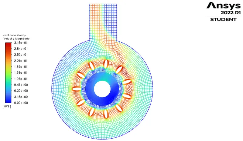
Velocity -
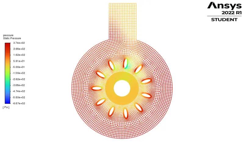
Pressure -
Solution Animation -
Case 2 -
Resuidal -
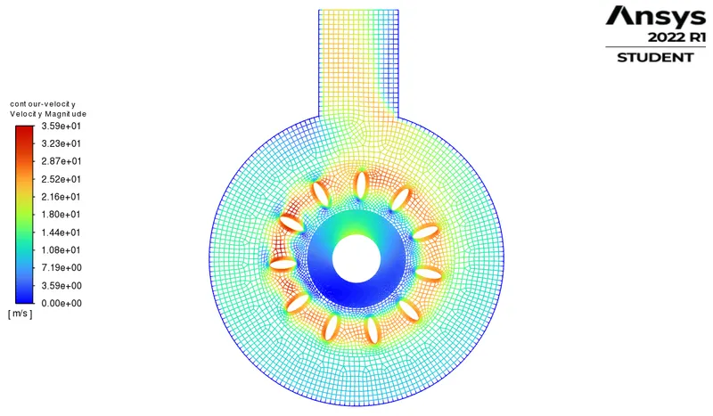
Velocity -
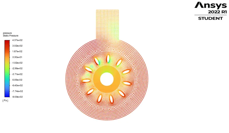
Pressure -
Solution Animation -
Concluison :
The velocity we maximum at the tip of the aerofoil and around the region of it, and the velocity seperation happens at the edge of the aerofoil. The static pressure is less at the inlet and rises as it moves towards the tailing edges of the aerofoil. From the velocity and pressure profile we can say thet the flow happens in anti-clockwise direction.