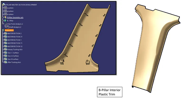
Week 9 - Project - Master Section Development
Aim: To create a manufacturable B-pillar interior plastic trim component from the A-Surface design.
Procedure:
Let us first understand what is a B-Pillar interior trim briefly, before we start modeling our part.
B-Pillar:
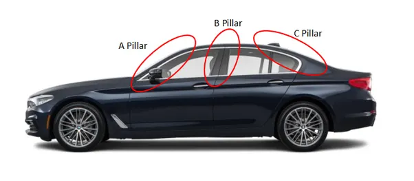
The B-pillar is a multi-layered component that primarily provides structural support to the roof and doors of the vehicle. It also houses the mounts for seat belts, airbags and is engineered for safety in side crashes. It has different alloys/steels of various strengths welded together to the floor panels and roof of the vehicle.
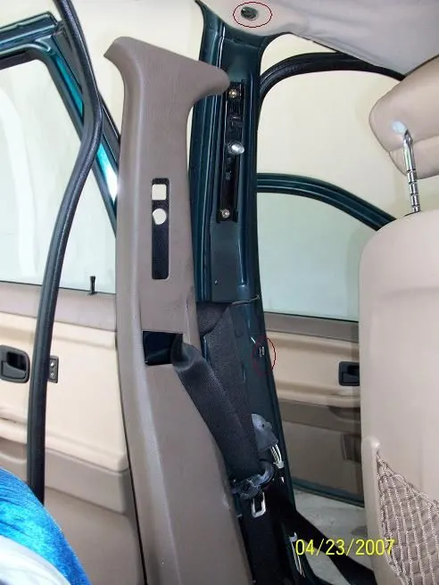
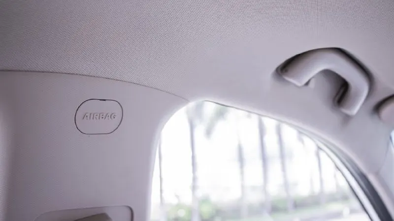
Unless the vehicle is used for races, where weight needs to be reduced, the B-Pillar metallic structures are covered by a plastic component on the interior. This plastic component may be exposed to the occupants or covered with fabric materials to provide a luxurious interior.
We will be designing this, interior plastic B-pillar trim using the provided A-surface and Master sections.
1.A-Surface inspection:
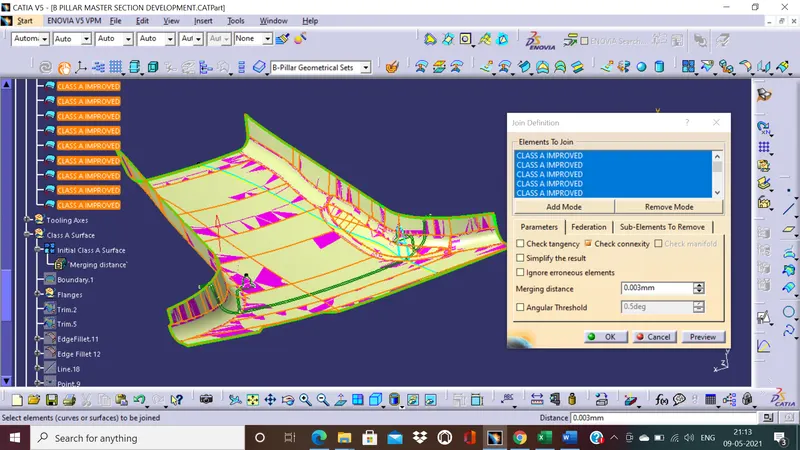
From the given A surface we use the Join operation to join all the surfaces to form one single surface. We check the gaps between the surfaces. If the gap is more than 0.003mm we need to rework on the surface and fill the gaps through various operations. The given surface has no gaps more than 0.003mm and can be joined forming one single surface.
2.Flanges:
The multisection we are given contains flanges which we need to construct on the A surface.
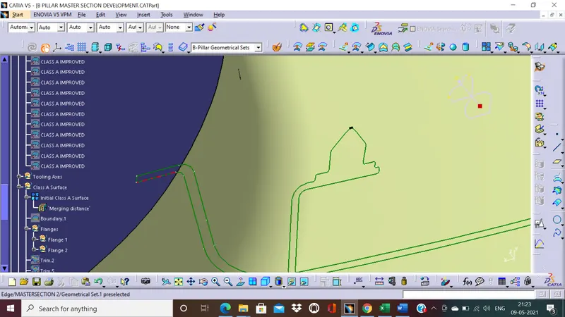
Using the multisection we need to create flanges. We extract the protruding edge surfaces and use the sweep command to trace a sweep that intersects around the multisection as shown below.
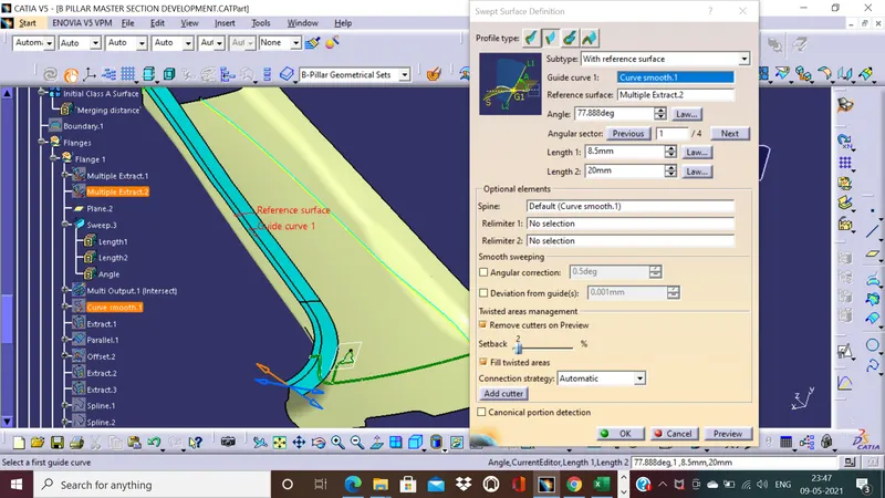
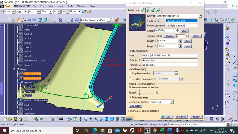
The same is repeated on the other flange.
We trim the two flanges to the surface and finally form the A surface now.
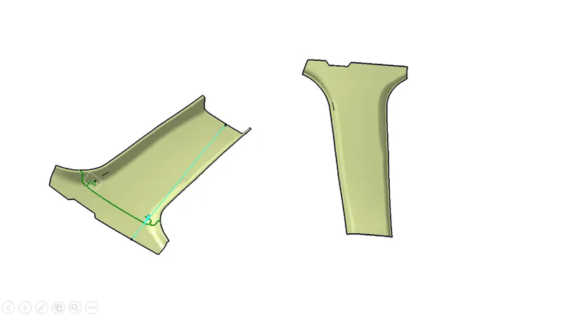
3:Tooling Axes:
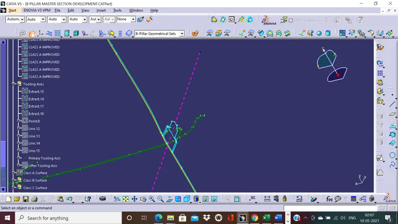
We observe the part in X Y and Z directions and conclude the best estimate for a tooling axis is in the Y direction.
Using the multisection we have, we form the tooling axis by extracting four lines from the master section from the location where a four-way locator exists.
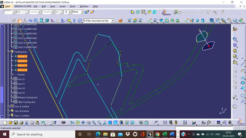
We bisect the lines that are opposite on the same master section line. The resulting lines formed are shown below.
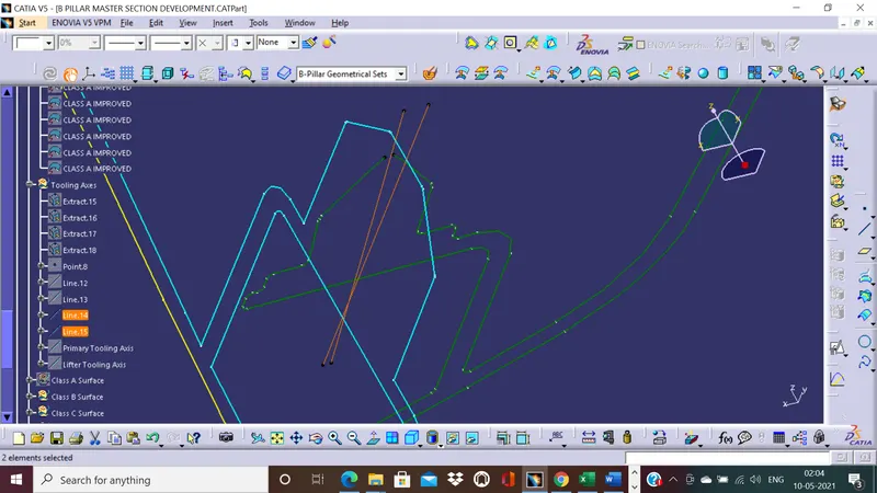
On bisecting these two lines, we have formed a tooling axis that would work. we perform a draft analysis on our A surface at this stage.
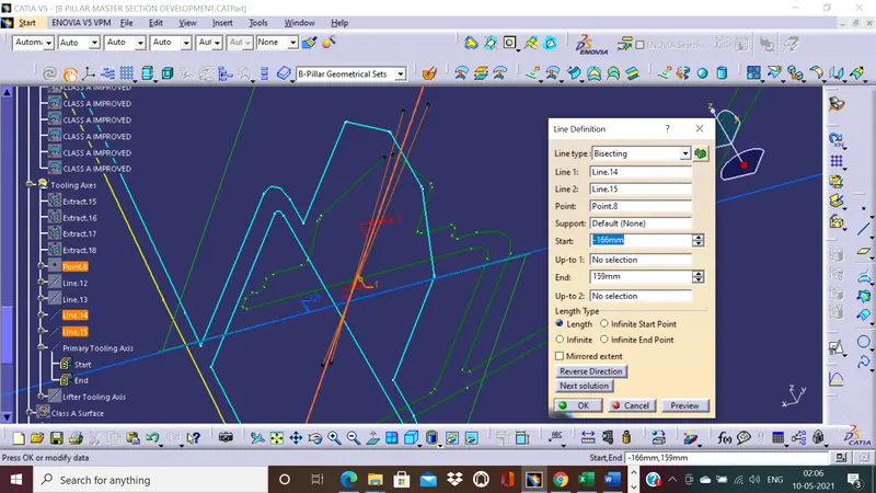
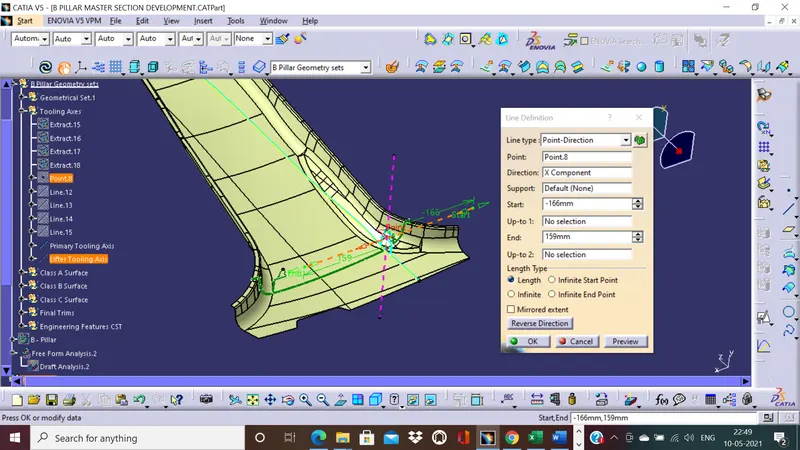
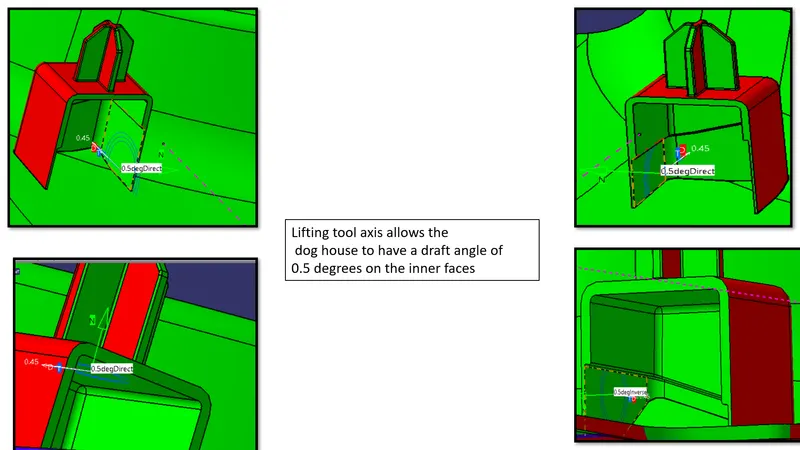
We would also be needing a lifter tooling axis to form the doghouse.
We use the same point used for creating the primary tooling axis and create a line in the X-direction. This line is our lifter tooling axis.
4:Class A Draft Analysis:
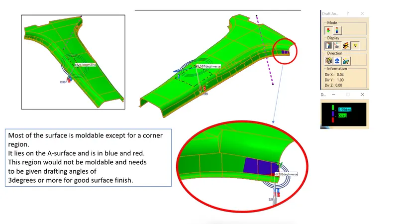
We perform a draft analysis using the A surface and tooling axis we have created. The output is shown below.
Color-Coded regions according to the draft angle from the tooling axis.
Green: Greater than 2.99 degrees
Blue: Between 0 and 2.99 degrees
Red: Below 0 degrees
5: B surface:
Using the Master sections provided, we can conclude that the part thickness is 2mm. We thus need to create the B surface at a gap of 2mm following the master section.
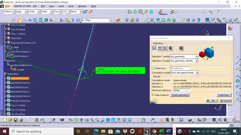
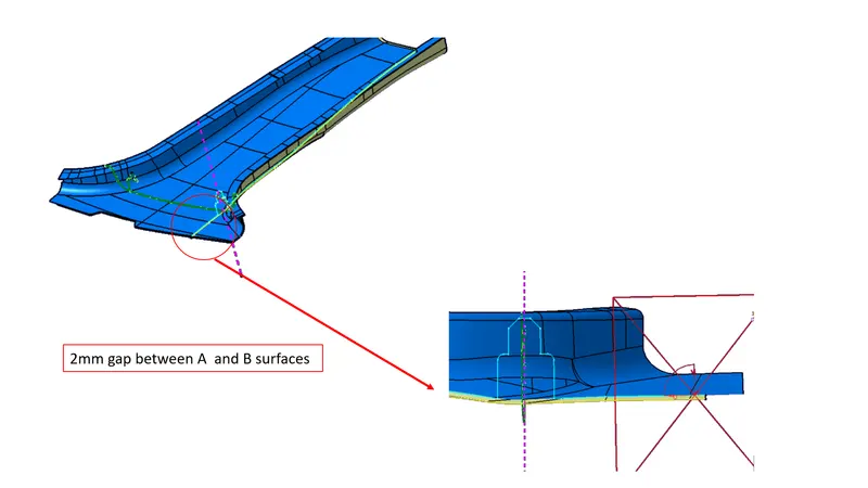
The edges of the B surface are extrapolated so that, it will be easy to trim it with the C surface we are going to make.
6.C-Surface:
To fill the surface gap between the A and B surfaces, we need to create a C surface. The C Surface needs to have a draft angle with the tooling axis we made. A minimum draft of 3 degrees is given to get a moldable part with a good surface finish.
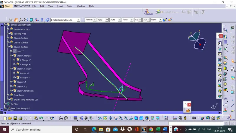
7.Trimming the A, B, and C surfaces together:
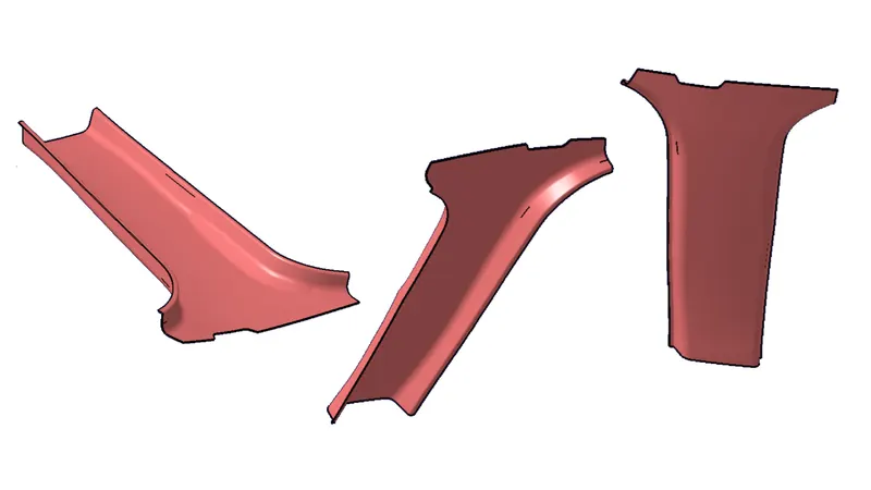
The final steps in forming the closed component are trimming the A, B, and C surface together. It is shown below.
We shift the workbench from the Generative Shape Design to Part design to convert the surface into a closed solid body.
8.Engineering Features:
After a solid body is created, we can add the engineering features to the B-surface side designing them with proper guidelines and drafting angles for tooling.
The engineering features added are - Dog house, 4-way locators, and ribs.
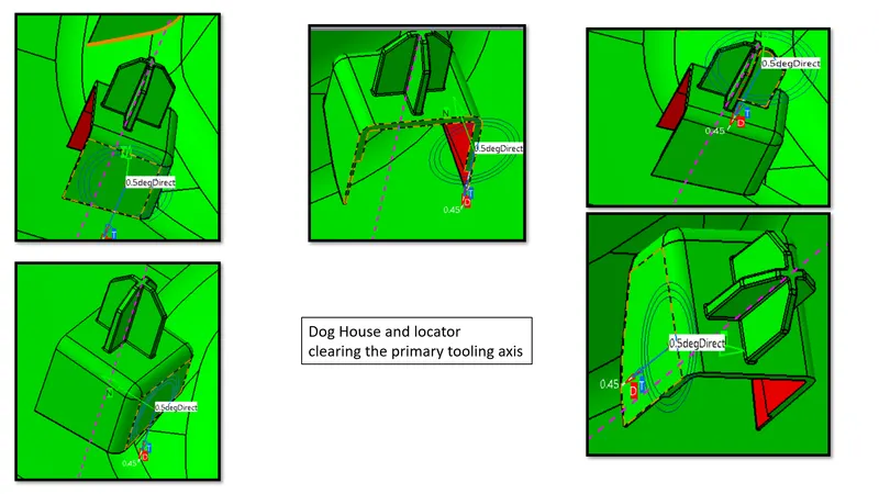
The base thickness of these features would be at 40% of the part thickness and have a minimum draft of 0.5 degrees from their tooling axis.
This is to avoid sink marks on the A-surface.
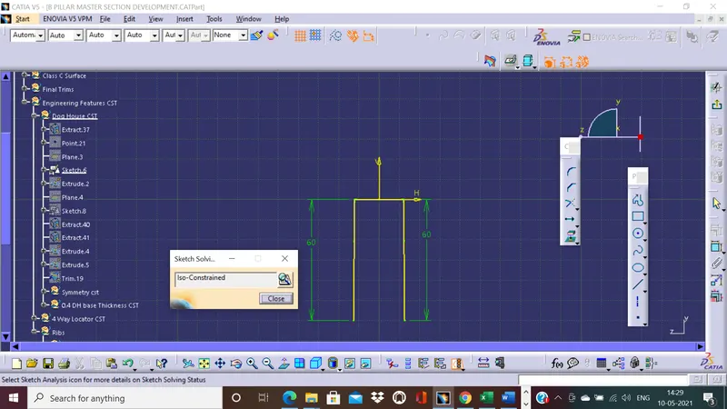
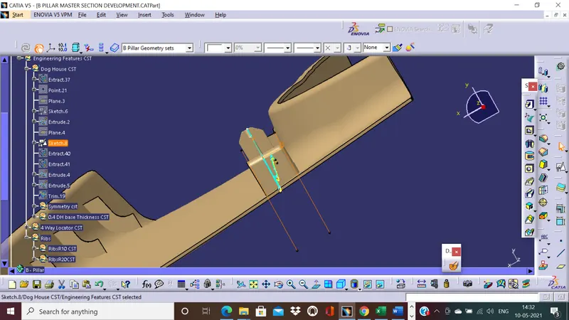
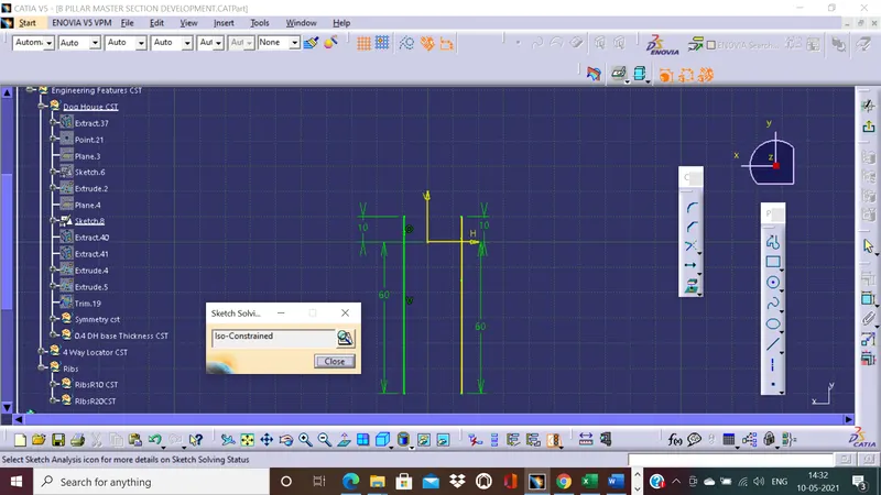
8a.Dog house: Constrained sketches of the dog house and locator following the master section
Base thickness is 40% of the component thickness.
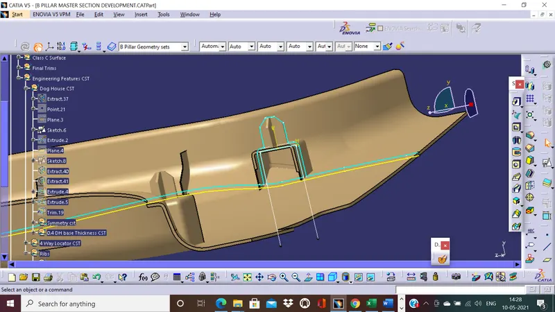
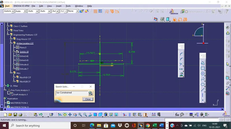
8b.4-way Locator: Constrained sketches of the locator.
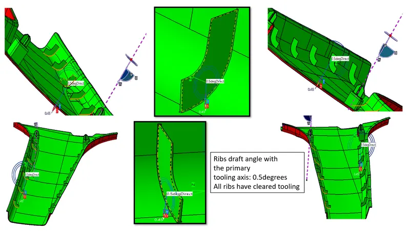
8c.Ribs: Constrained Sketches of the Ribs. Distance between ribs must be at least 50mm.
We have used around 100mm in our case.
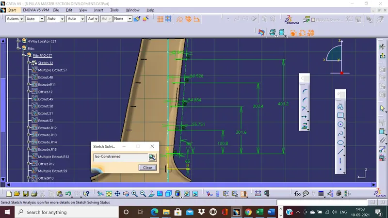

Tree Structure:
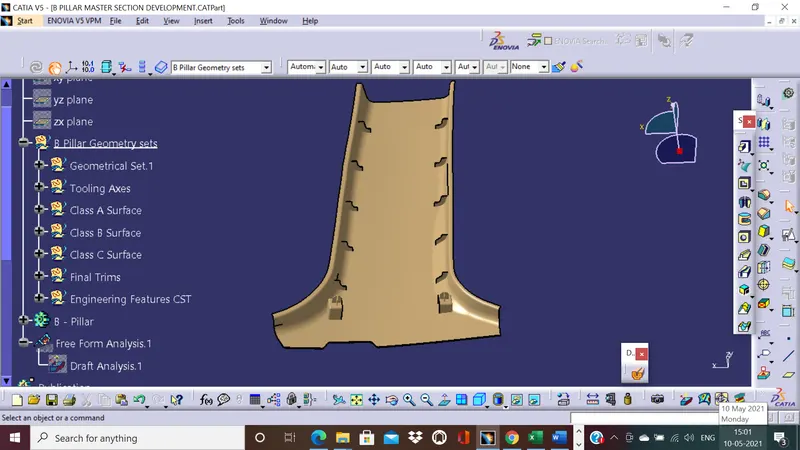
Class-A Tree structure
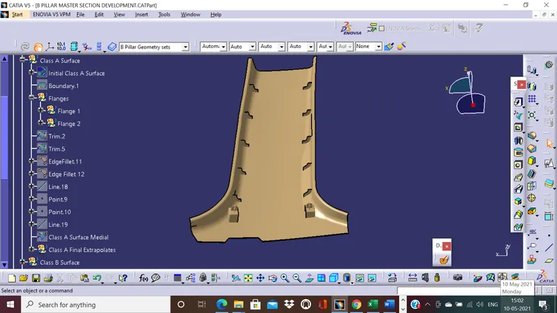
Class-B tree structure
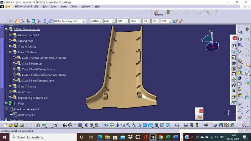
Class-C tree structure
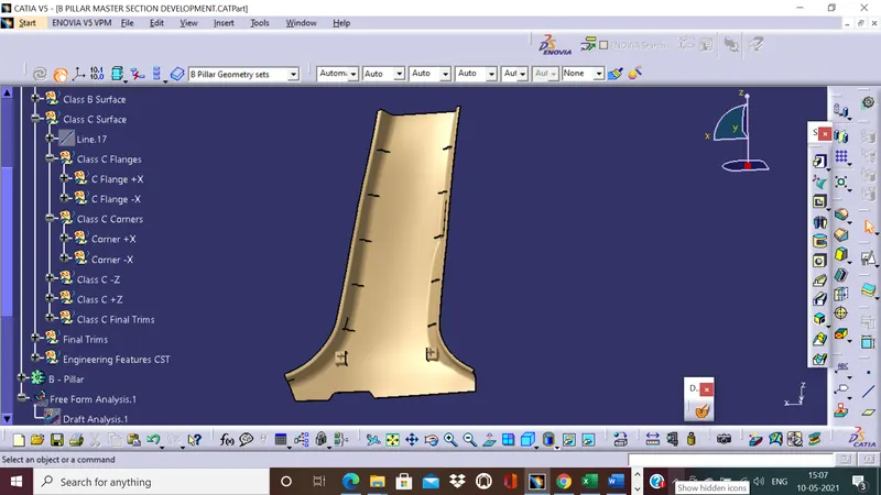
Engineering Feature tree structure
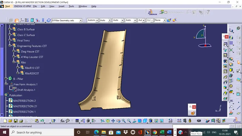
Dog House tree structure
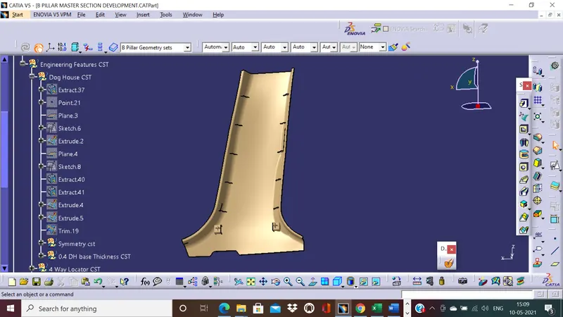
Ribs Tree Structure
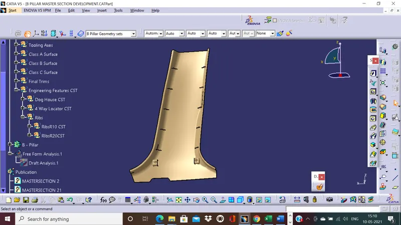
Body union trimmed structure with engineering features
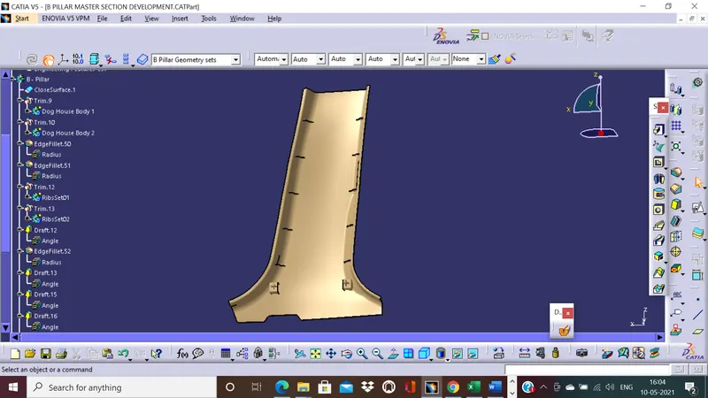
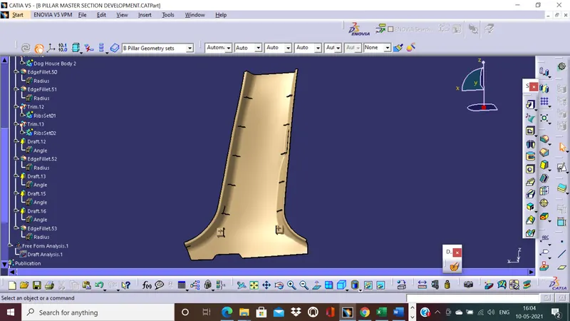
Final Product Draft Analysis:
Color codes with respect to draft angles from the primary tooling axis:
Green >2.9 degrees from the tooling axis
Blue between 0 and 2.9
Red<0 degrees
Observations
A-Surface and C-Surface side of the B Pillar:
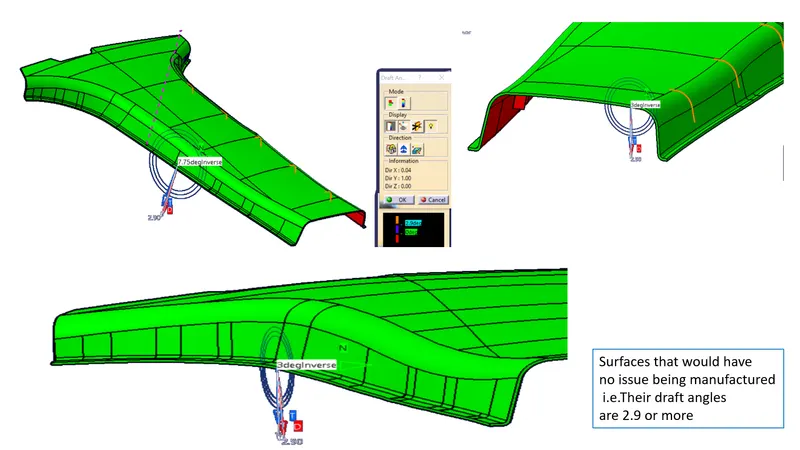
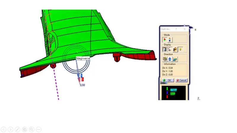
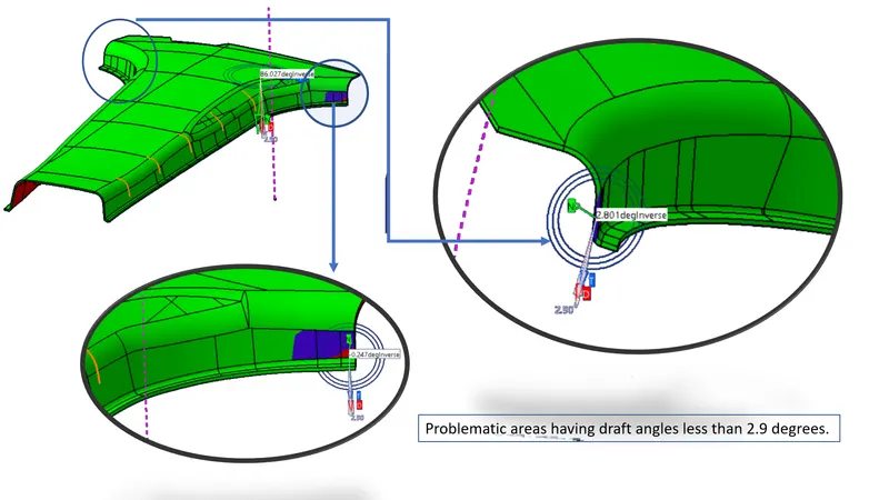
The surfaces above are all having draft angles of more than 2.9 degrees from the tooling axis.
We however have small areas that may be troublesome to mold because the areas are in the blue and red color region. The surface finish would be low and the undercut regions in red would cause issues in getting the component out of the mold. These regions need to have a draft in the A-surface model itself.
B Surface draft observations:
The color-coded draft regions are still the same as in the A and C surface.
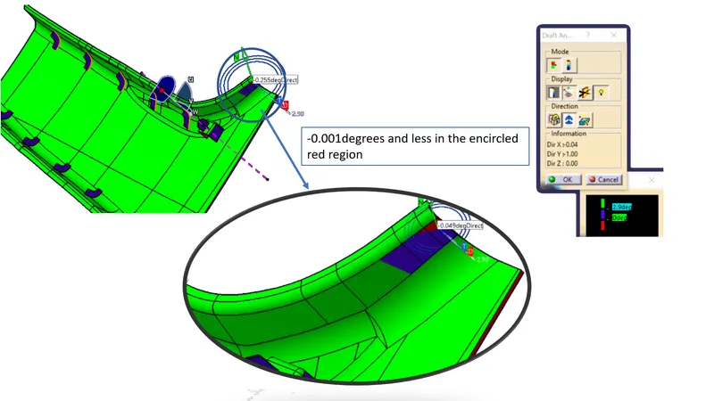
The maximum area on just the B-surface is having a draft angle greater than 2.9 degrees however there are spots displayed in the above pictures displaying problematic areas. This needs to be reviewed by the A-surface designer.
Engineering features color code for drafted regions:
The engineering features do not require a great surface finish; so the drafts for engineering features must be focused on moldability and functionality without damaging the A-surface area.
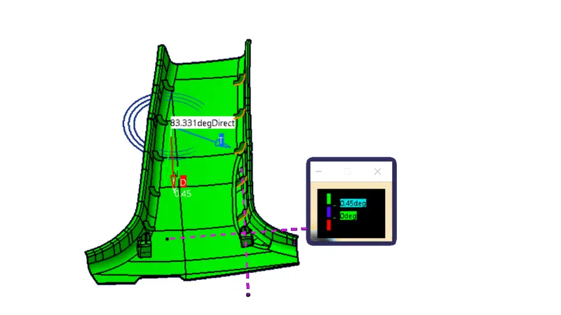
So we can give a lower draft angle of 0.5 degrees from the tooling axes.
New color spectrum:
Green: >0.45 degrees from tooling axis
Blue: between 0 and 0.45
Red:<0 degrees
Dog House and 4-way Locators:
Ribs:
All the created ribs have a draft angle of 0.5 degrees from the primary tooling axis.
They are all cleared for molding. The screenshots are shown below.
Conclusions:
After going through the observations and recorded screenshots, it is best advised to tweak the class A-Surface to reduce the undercuts we seen in our observations.
A minimum draft angle of 3 degrees from the tooling axis needs to be implemented into those two corners. They are shown below again.
Besides these areas of concern, the B-Pillar is moldable and could have an excellent surface finish visible to the occupants of the vehicle.
These corners have a negative draft and would but needs a slight.