Week 8 - Challenge 3 - Switch Bezel Design
Tooling Axis Creation:
1:The first step in creating the tooling axis is observing the Class A surface and joining the different surfaces to form one complete Class A surface.
2.The next step is checking the continuity of the surfaces using boundary operation. There was a discontinuity observed which was between 0.001 and 0.003mm. By increasing the merging distance a continuous Class A surface was created.
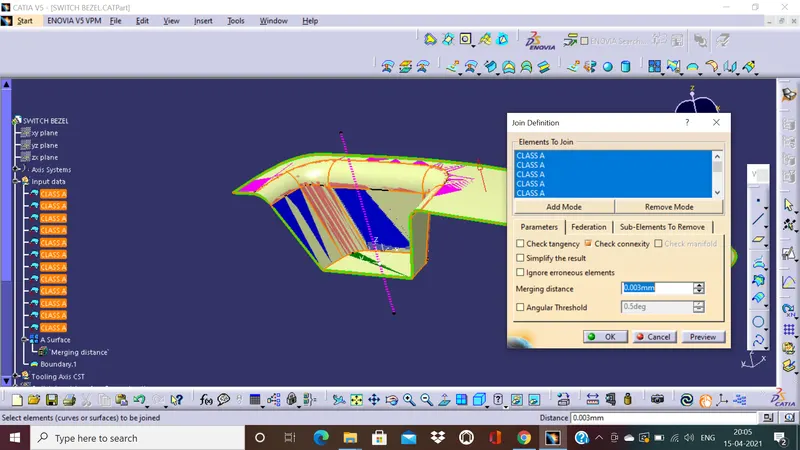
3. Now we create a new geometry set and name it Tooling axis CST. In this geometry set firstly we extract the base surface and create a point at its center. We use this point as the center of our tooling axis because only the surface that has fillets and slopes down would be a problematic area. An axis system is created using this point.
4. Now we intersect the A surface and YZ plane to form an intersection line.
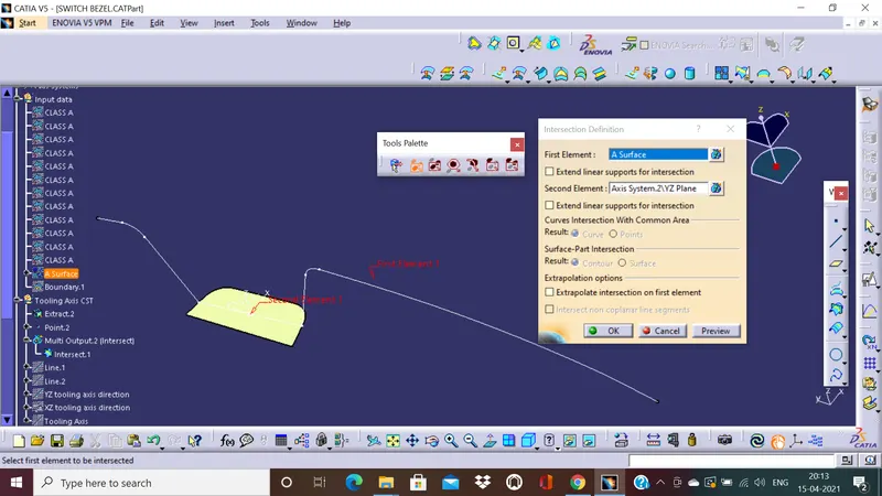
5. We can now create and extend the lines that are almost parallel to the Z-axis.
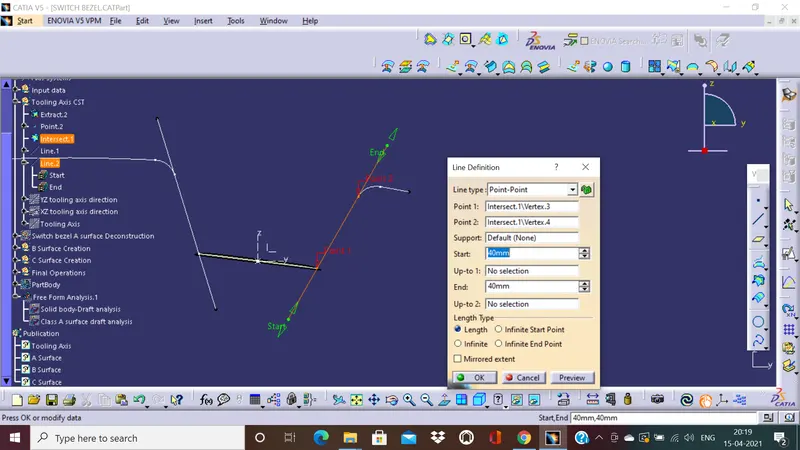
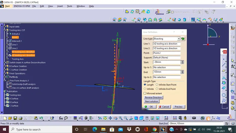
6.Now we need to bisect these two lines. Using the bisect type line, we use Line1, Line2 and the point we created to form the Y direction tooling axis.
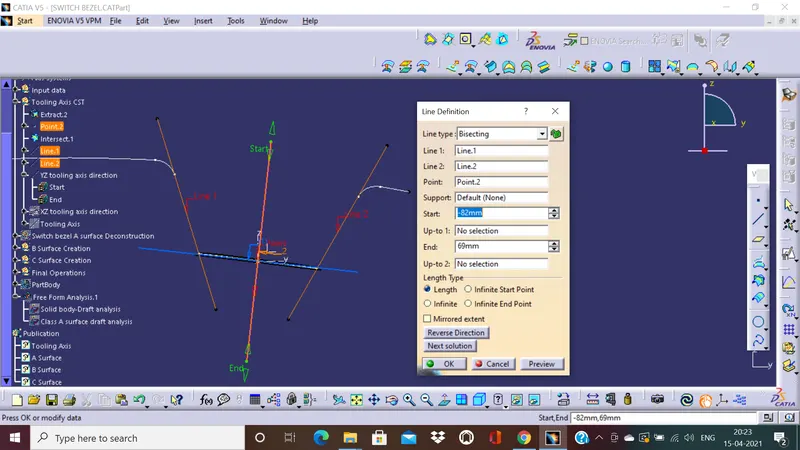
7.Our next step is creating the XZ or X direction tooling axis. We can make a sketch for this line. Using the XZ plane and the point for the sketch support, we can intersect the 3D elements onto the plane and make it a reference line. Using the reference intersections, we create a line that is collinear to it and also a line that passes through the center point. This line is then angled at 6 degrees from the other line. 6 Degrees because we observed in our draft analysis that, we are not clearing our minimum draft angle of 3 degrees sufficiently.
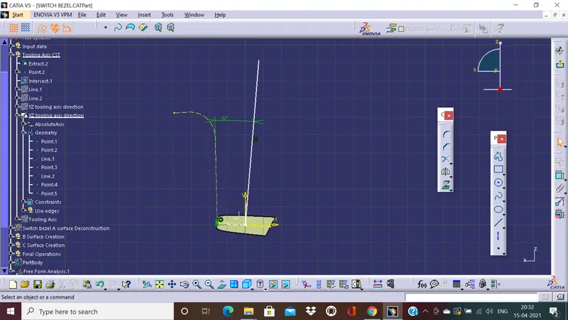
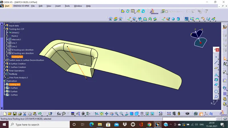
8. Now we come out of the sketcher and are in a position to bisect the two lines, i.e. the Xz direction tooling line and the YZ direction tooling line. We go to the line option and create a line using the bisecting line type. The two lines we created and the center point will provide us the tooling axis we need for manufacturing the part.
Class A Draft analysis:
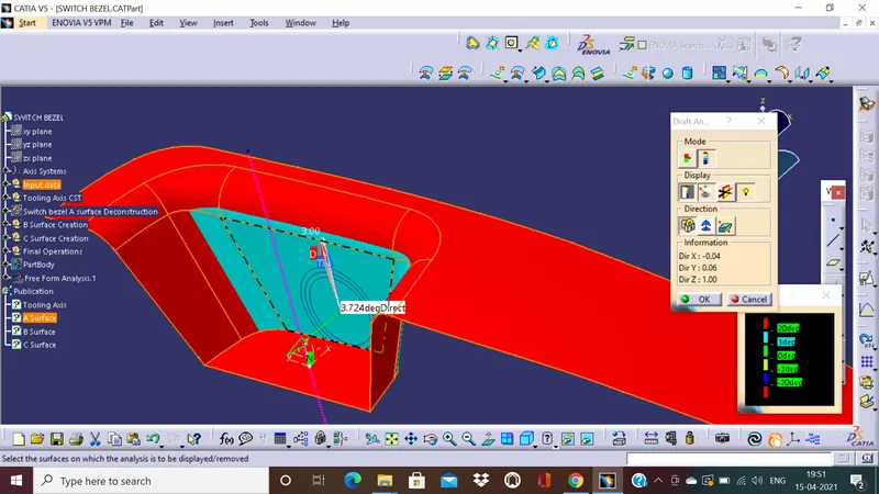
Color region codes for draft angle with the tooling axis:
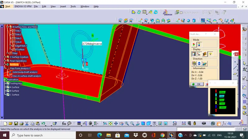
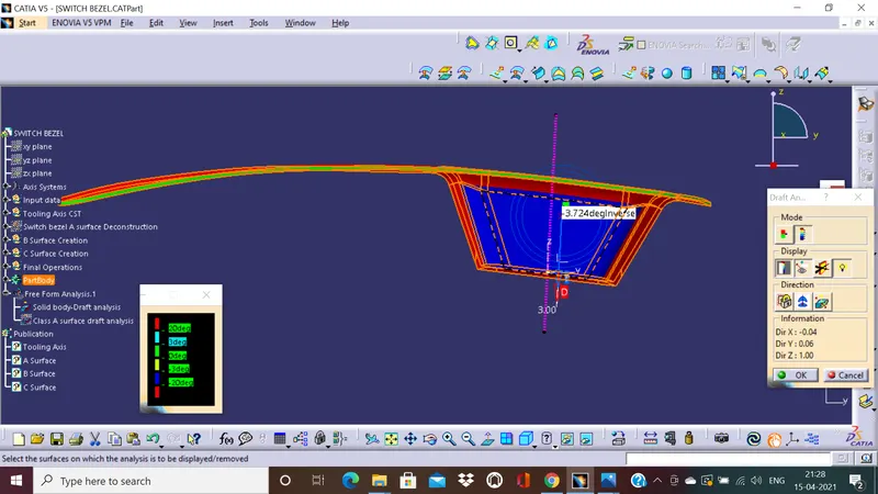
Green : 0 to 3 Degrees; Yellow : 0 to -3Degrees
Cyan: 3 to 20 Degrees; Blue: -3 to -20 Degrees
Red: 20 to 90 degrees and also -20 to -90degrees
From the draft analysis, we see that the lowest draft angle recorded is 3.72degrees for the steep fall of the part. It is the cyan region as shown below.
The other regions have draft angles that would not cause any issues. They are shown below.
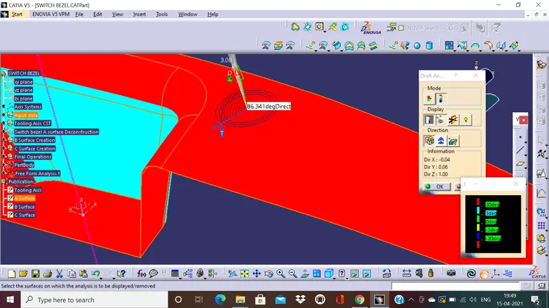
86 degrees at the top armrest surface
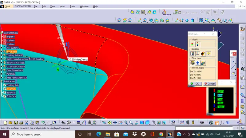
20 degrees at the fillet region.
Overall, the Class A surface can be manufactured with the tooling axis we have set it for.
Final model draft analysis.
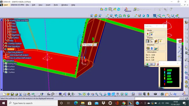
We are getting a draft angle of 2.977 degrees at some of the edges from the C surface. The initial draft analysis for the same spot was 2.5 degrees when the X tooling direction was created with a 3 degree draft in our sketch. By changing that angle to 6 degrees, we have bought it to a range that may be acceptable without causing issues.
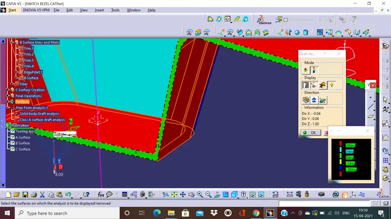
3 degrees at the bottom surface
Orientations of the model during draft analysis:
Side views:
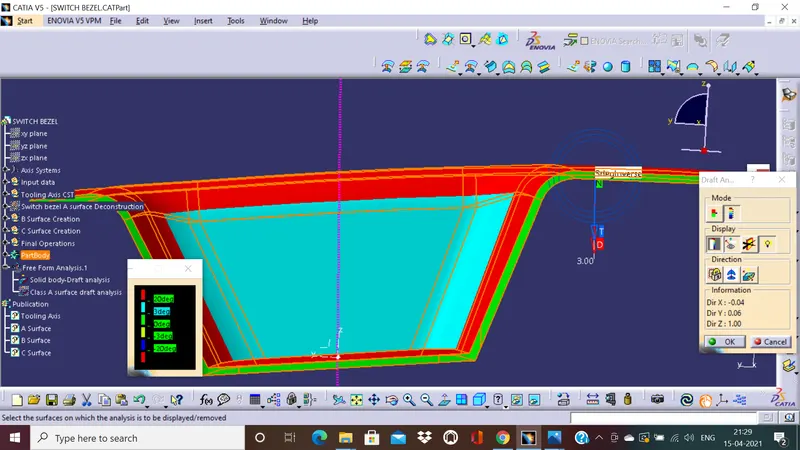
Front views:
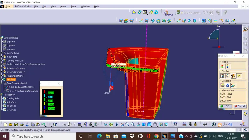
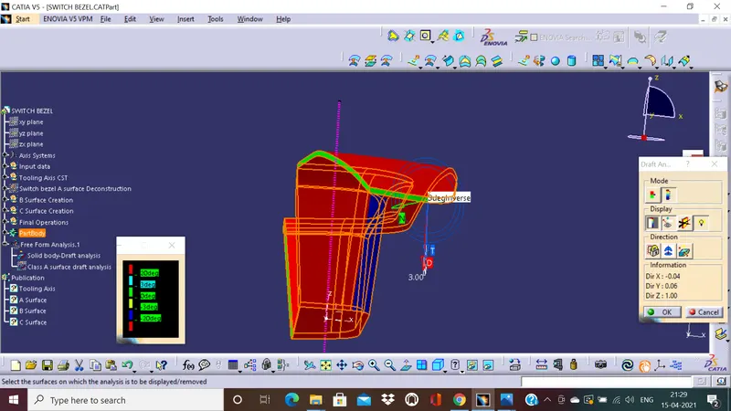
Top views:
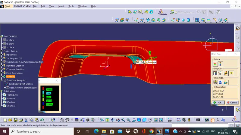
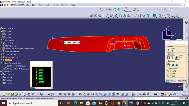
Isometric view:
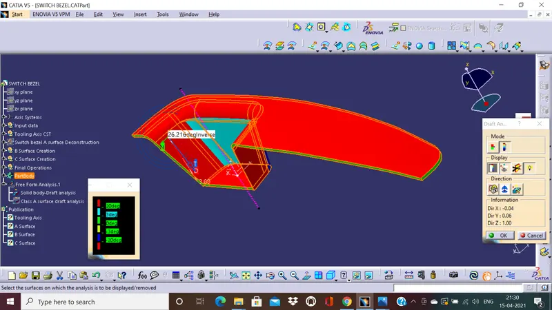
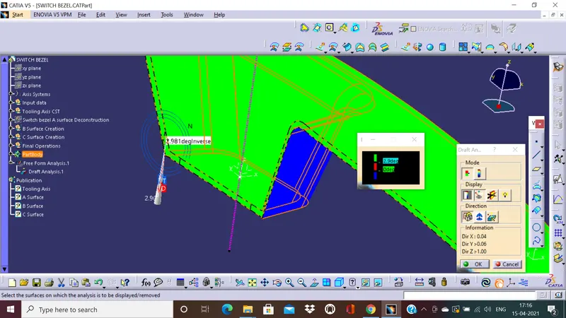
Overall the part can be molded with little to no defects due to the minimum draft angle of 2.9 degrees recorded on the part from the tooling axis.
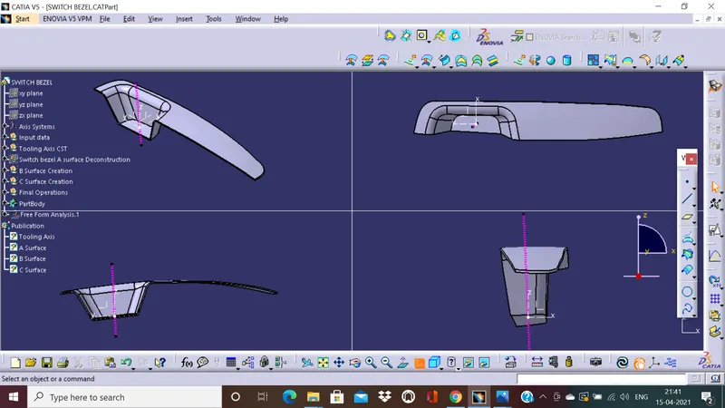
Model views in different Quadrants:
Q1:Top view
Q2: Isometric view
Q3: Side view
Q4:Front view
Please see the cat part in the zipped file. Thank you.