Week 8 - Challenge 4 - Coin Holder Design
Aim: To perform the draft analysis on the given A Surface part and conclude if the part is manufacturable or not.
Procedure:
We need to first create the tooling axis to perform the draft analysis.
Steps in the creation of Tooling Axis:
1.We first extract the surface that is perpendicular to the area or region that we think is almost parallel to an estimated tooling axis.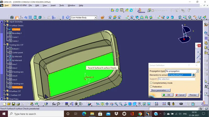
2.Then a point is created at the center of the surface we have extracted.
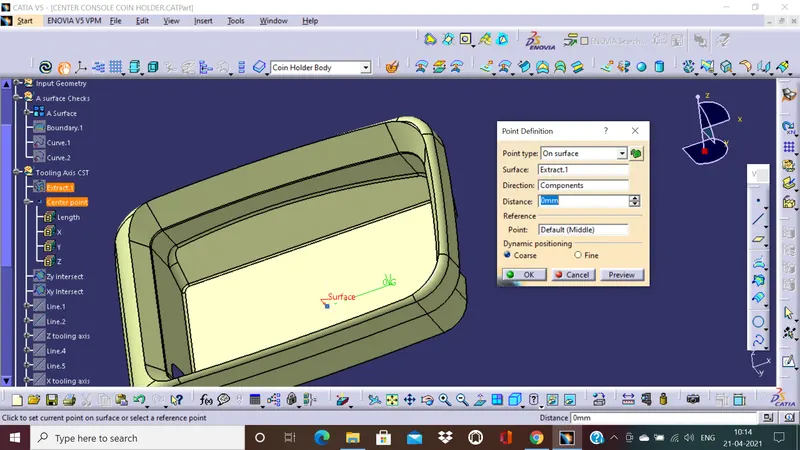
3. We use this point to create an axis system and make sure the current checkmark is unchecked.
4. Now create two intersections of the A surface with the ZY plane and the Xy plane of our axis system.
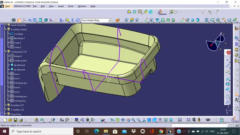
5.We will work on the Zy intersect first and extend two lines by using 4 points that we think are parallel to our estimated tooling axis.
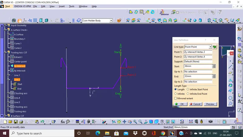
6.A new line is created by bisecting these two lines at the center point and this new line is the Z tooling axis.
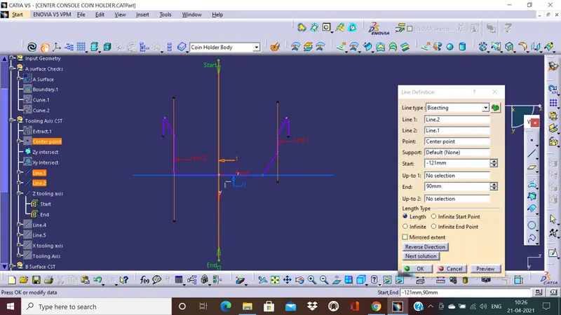
7.Similar steps are followed for creating the X tooling axis.
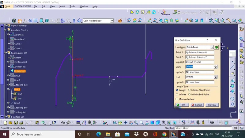
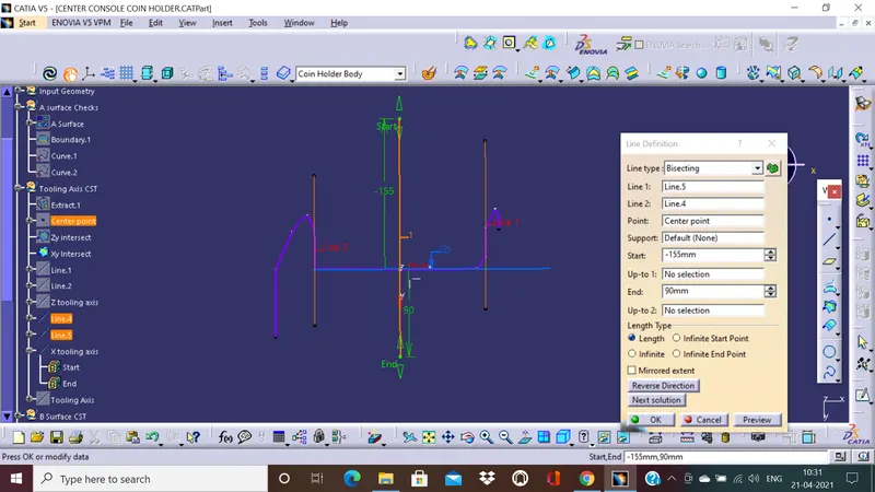
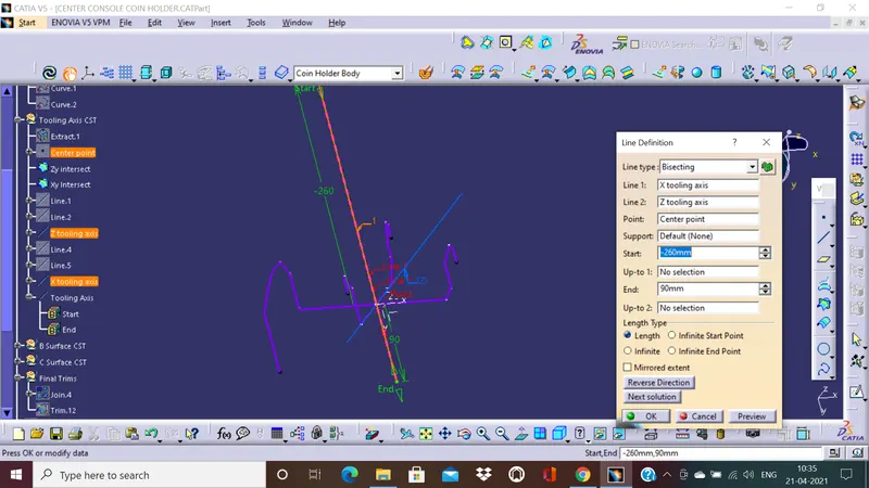
8. The final step in creating the tooling axis is to bisect these two tooling axes i.e. X tooling axis and Z tooling axis, that we have created. We make the new line pass through the center point.
Draft analysis:
1.Using the tooling axis we created we perform the draft analysis on the A surface.
We first need to understand the color codes of the draft with respect to the tooling axis, they are as follows-
Red- 0 to 3 degrees draft angle
Green- more than 3 degrees draft angle
Blue- negative draft angle.
Observations:
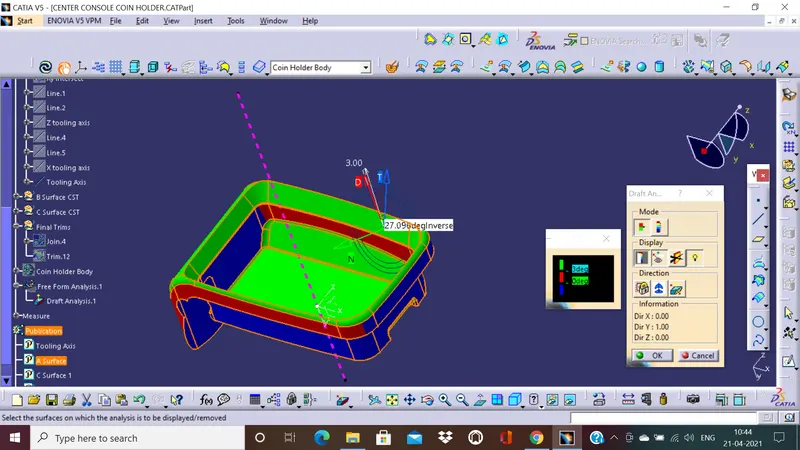
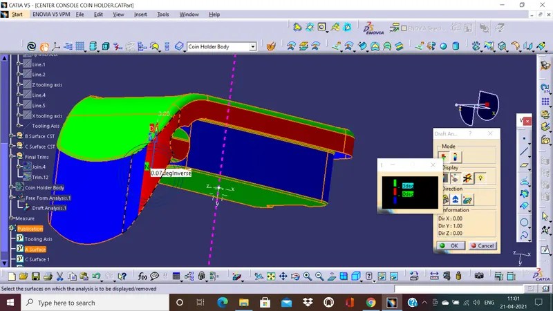
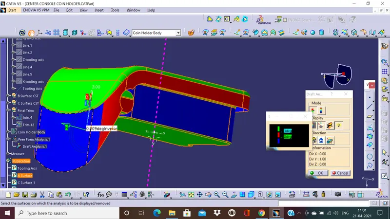
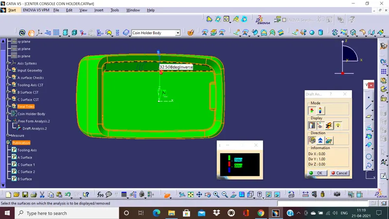
From the color codes, we are observing that the class A surface has been designed without considering draft angles.
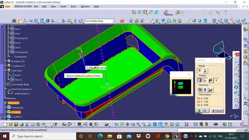
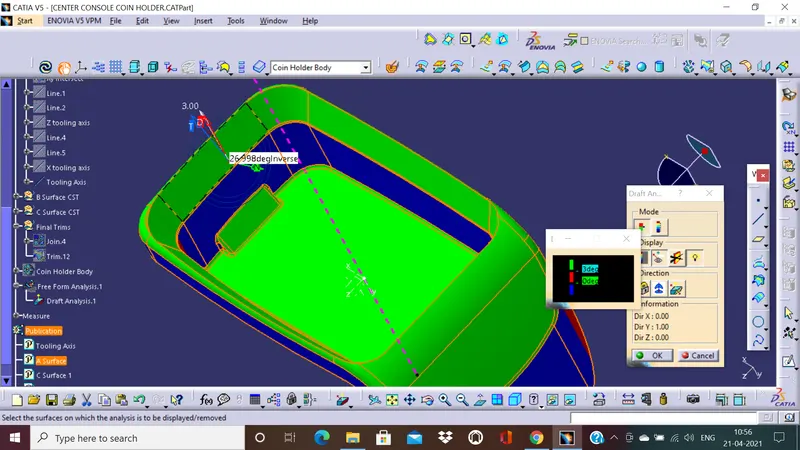
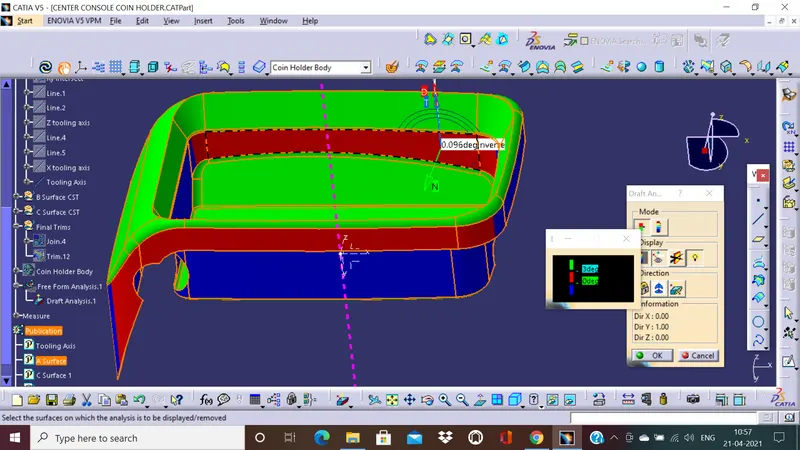
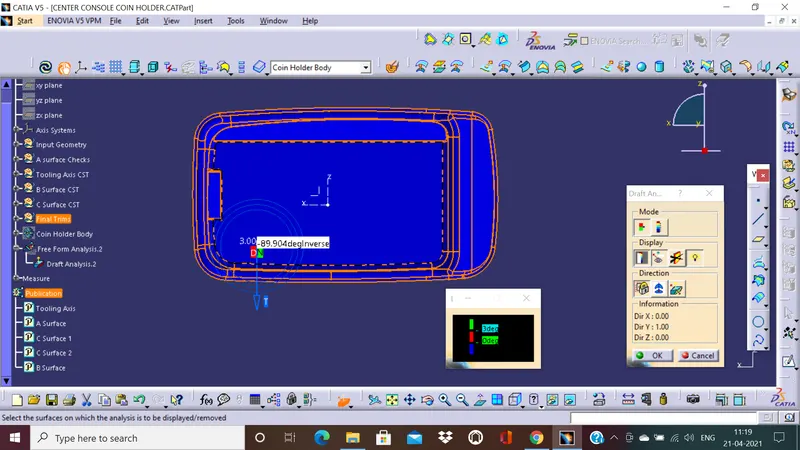
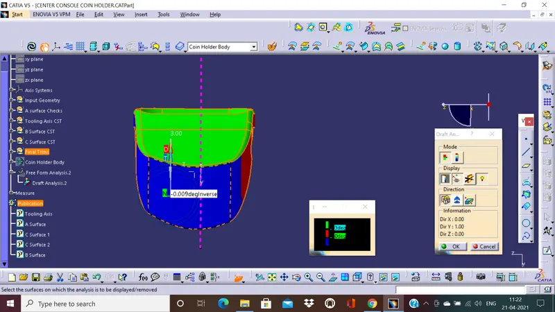
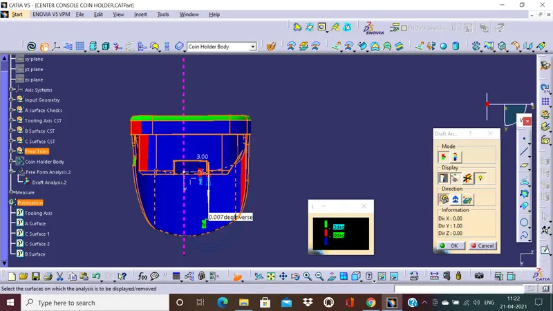
The regions we assumed are parallel to the tooling axis are in blue color which signifies they have a negative tooling axis. We observe this on the inner part of the surface as shown below. The draft angle here is -0.096 degrees. The regions in red have a draft angle of 0.096. We can say that the inner regions of the part are parallel to the tooling axis. The flanges also exhibit the same color codes.
Conclusions:
The regions in red and blue on the model that is between -3 and +3 degrees need to be solved on the A surface if the part has to be manufactured using injection molding techniques.
The A surface design needs to accommodate a minimum of 3 degrees draft angle on all the surfaces from the tooling axis.
Without these draft angles taken into consideration, the A surface finish will not be desired by the customer and the part will be unable to pass quality checks.
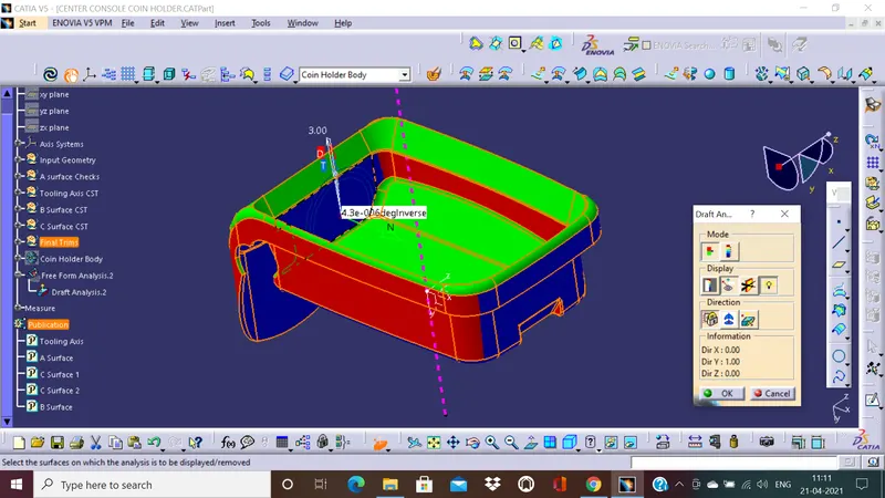
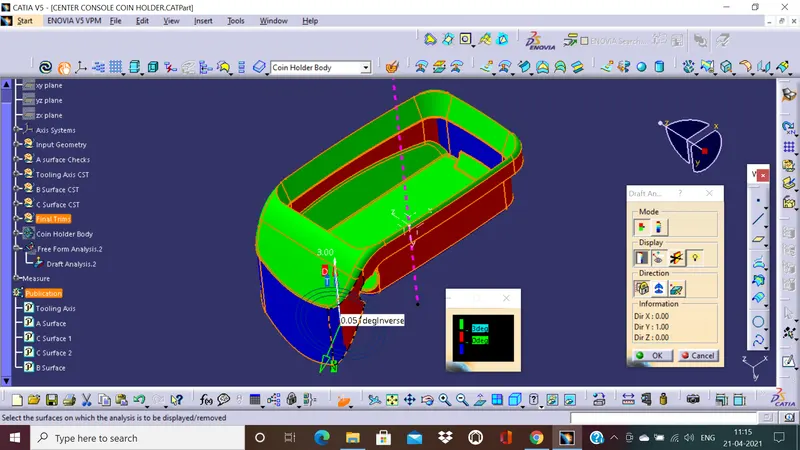
Screenshots of the draft analysis on the 3D model in different orientations:
Isometric views:
Side views:
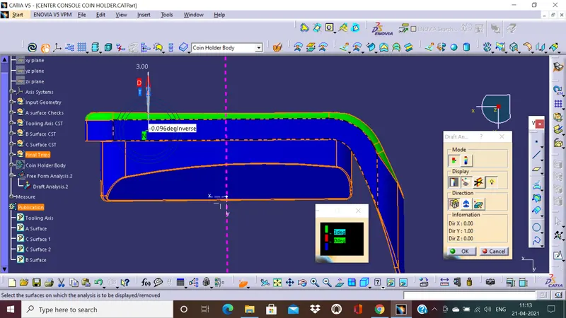
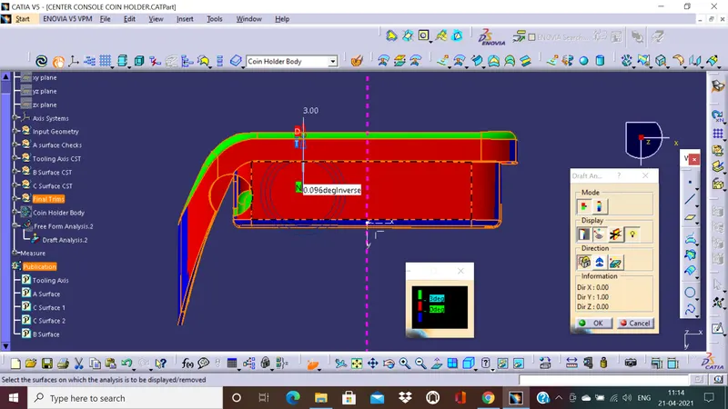
Top and Bottom views:
Front and back views:
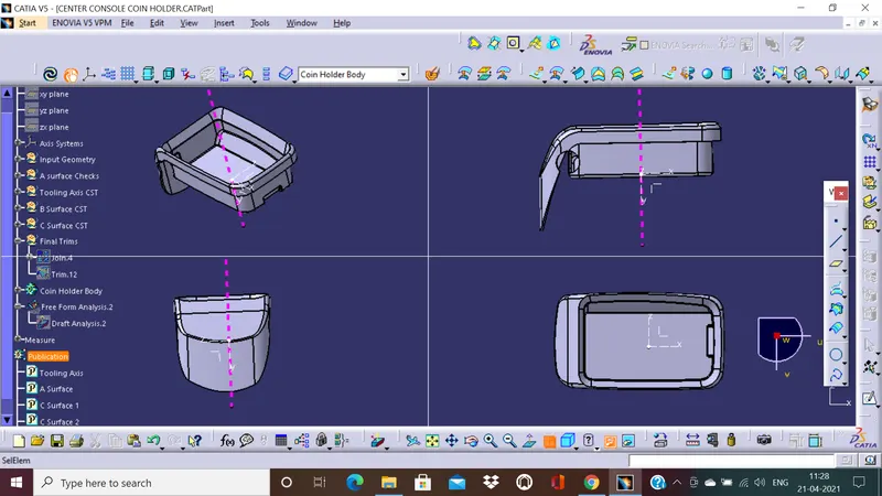
3D Model views:
Q1:Side view
Q2:Isometric view
Q3:Front view
Q4:Top view
Please see the cat part in the zipped file. Thank you.