Door Arm Rest Week 8 Challenge
Door Arm Rest Draft analysis Report:
Aim: To create the required part and perform the draft analysis on it.
Draft analysis:
Before performing the draft analysis, we first need to establish a tooling axis for the part to be manufactured from. The tooling axis will enable us to create the C surface draft angles.
Procedure: Creation of the tooling axis on the A surface.
1.We first need to estimate a tooling axis keeping in mind the surfaces that the customer would be likely to see. The input Geometry shows the door and the orientation of the armrest we need to model.
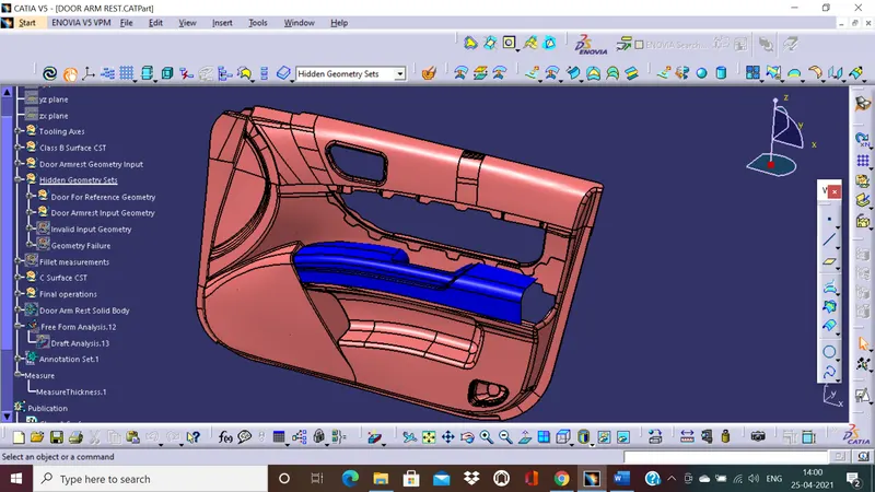
By the reference geometry, we see that the armrest's upper wall and outer wall will be seen by the customer and this should be the surface we give maximum priority to.
2. We form our A surface and estimate a tooling axis that is in the Z-direction passing through the center of the hole in the part.
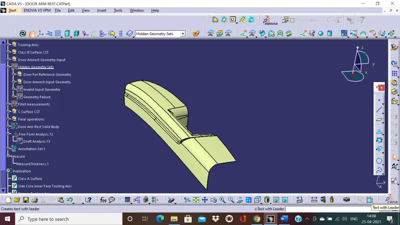
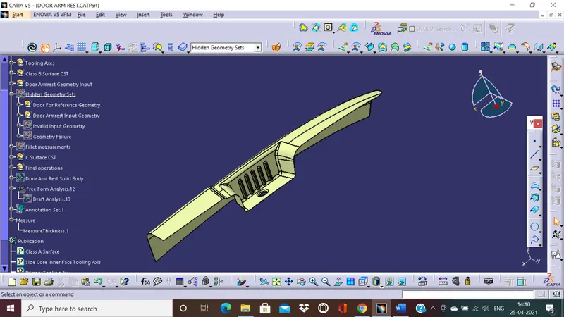
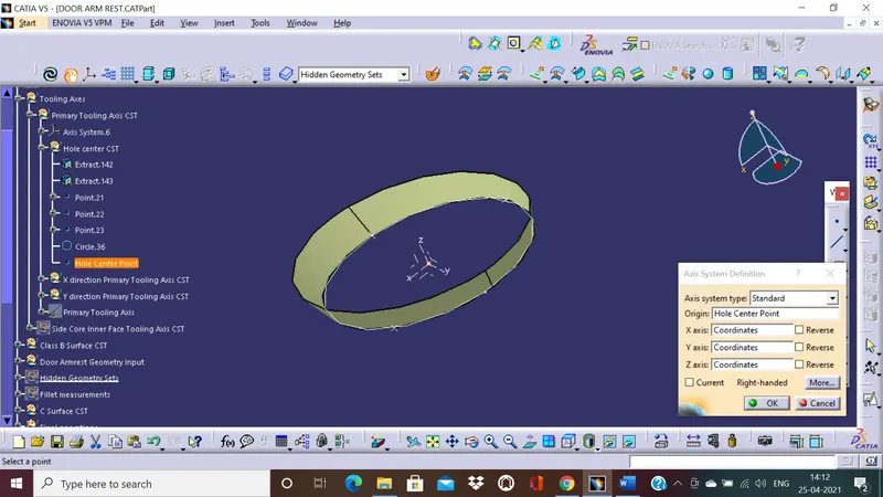
3.We extract the surfaces forming the hole, create three points along the edge, and first create a circle. Once the circle is created, we use its center to form the center point of the tooling axis. A new axis system is created keeping the center point as the origin.
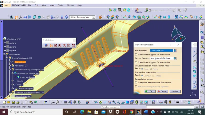
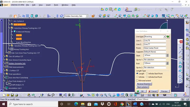
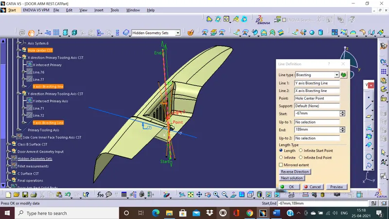
4. Next, we create the X intersect using the ZX plane from our axis system. We extend the lines that are almost perpendicular to the Z-axis. We observe that the hole extracts would have these two lines. We extend them and create another line that bisects both the previous two lines. The new line would be the X tooling axis line.
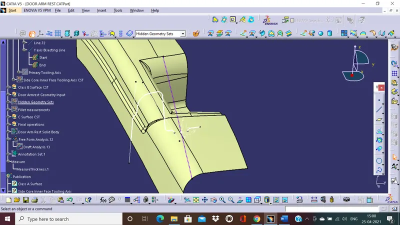
5. Similarly we create the Y intersect and the Y tooling axis. We check the slope of the wall and the hole and realize, the wall has a steeper slope or lesser angle to the Z axis and extend the lines forming the wall on the Y intersect. The Y tooling axis is created bisecting the two extended lines.
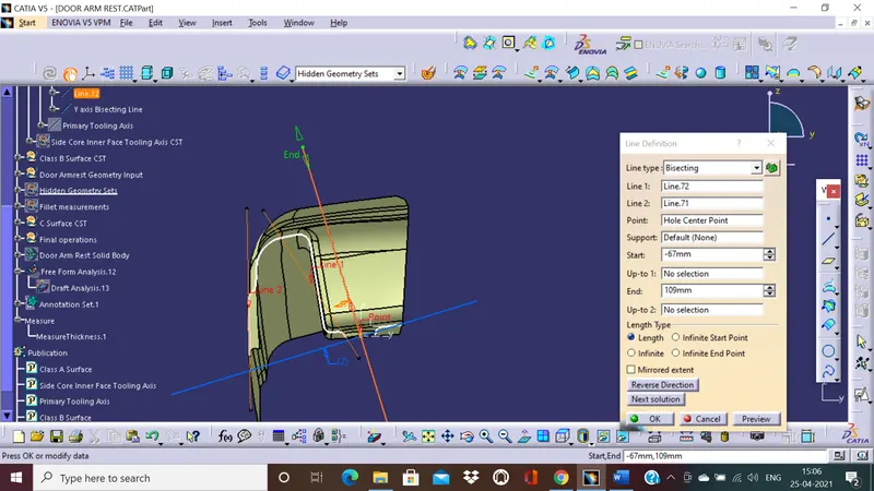
6. We next bisect the Y tooling axis and X tooling axis. The bisecting line can be our preliminary or final tooling axis if it clears the 3-degree drafting angle for the part.
Observations:
Draft analysis of the A surface.
Color Codes:
Greater than 3 degrees - Green Color
0 to 3 degrees - Red color
Less than 0 degrees - Blue color
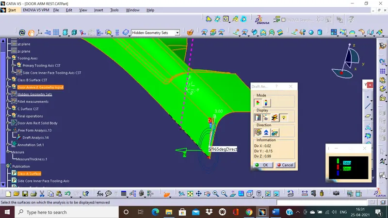
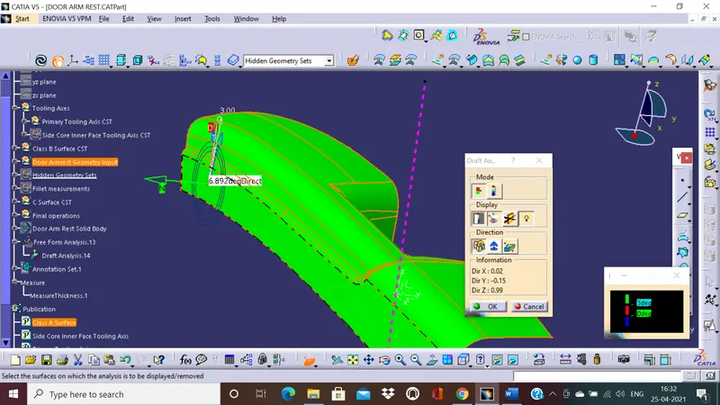
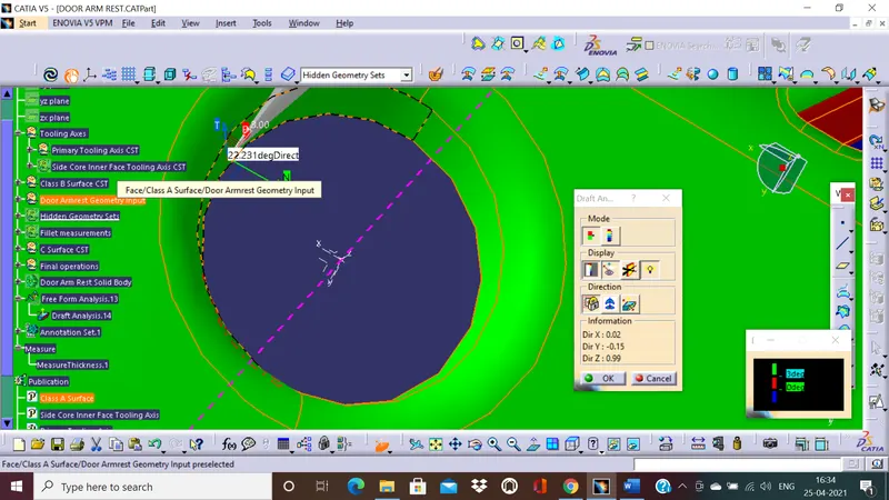
From the above screenshots, it is evident that the tooling axis created using the primary tooling axis line forms a draft angle greater than 3 degrees with the part created in the regions that the customer can see and feel i.e the outer wall and top wall. The surface quality will be of a good finish in these regions.
Problematic areas:
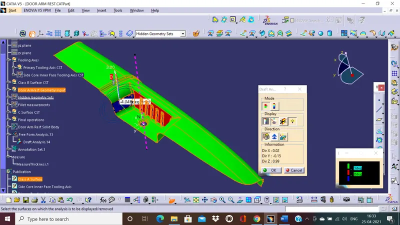
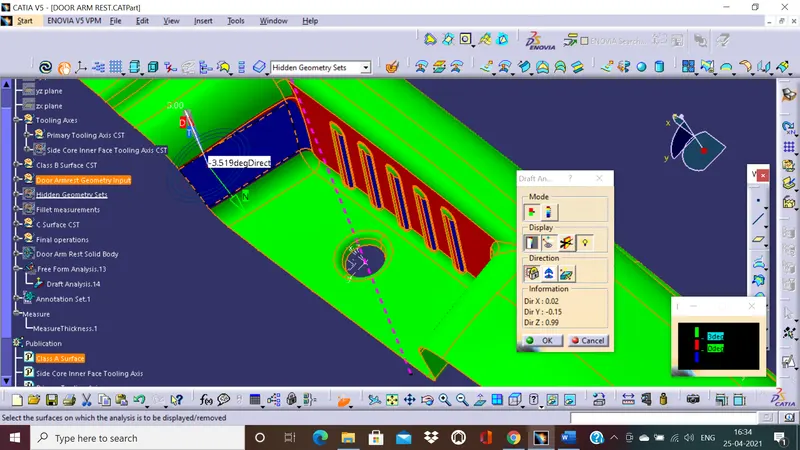
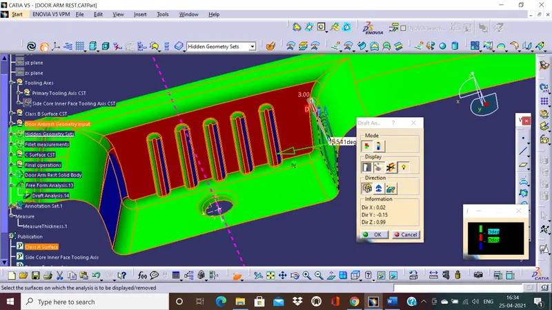
The inner surface of the component has regions colored in red and blue. This indicates that the tooling axis we created, does not clear these areas with a minimum 3-degree draft. The red regions are between 0 to 3-degree draft angles and the blue region is having negative draft angles which means we are having an undercut. If we get an undercut region, the molds will not be able to separate open without damaging the component. After several attempts at modifying the tooling axis, we conclude that we do not have an axis that clears both the inner as well as the outer face of the component.
It is now necessary to consult the A surface designer. We need to consult whether the inner surface can be modified or not.
If no modifications are possible to the A surface, then we need to resolve the issue by making a side core that requires a side core tooling axis for the inner surface.
This tooling axis is created only keeping in mind the inner problematic face and not the outer components.
Side Core tooling Axis:
Procedure:
We create a new tooling axis keeping the inner face perpendicular to our new axis.
1. We first extract the inner face and untrim it. We then create a new point using the untrimmed surface. This new point has to be at 0 and it becomes the origin of a new axis system we create.
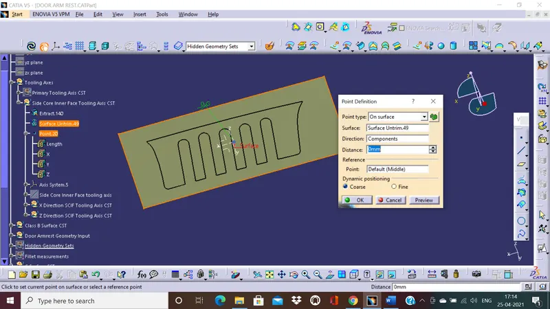
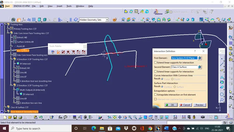
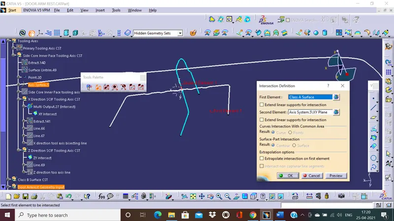
2. Now we are in a position to create the X and Z intersects with the A Surface and the XY and ZY planes.
3 X-direction side core tooling axis
We extend the inner faces of the X intersect that are almost parallel to the Y-axis, and after bisecting them we create the X-direction side core tooling axis as shown.
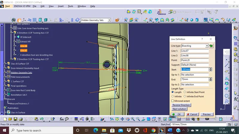
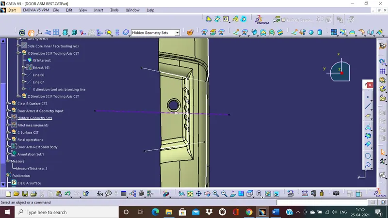
4. For the Z-axis, however, we create a sketch that we can manipulate to obtain an angle that is desirable in our final side core tooling axis. We do this because the top surface of the inner face is open and we only have a bottom surface. We extend the bottom intersect line and then create a line that passes through the side core center point. The sketch line is angled from the bottom face extended line. We manipulate this degree angle to obtain the final side core tooling axis.
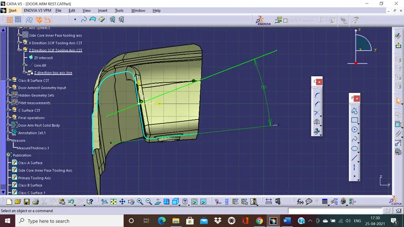
5. We now bisect the X side core tooling axis and Z side core tooling axis to get our final side core tooling axis.
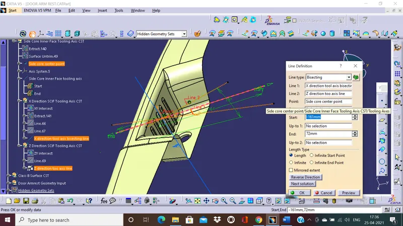
Observations:
Side Core Tooling axis - Draft analysis
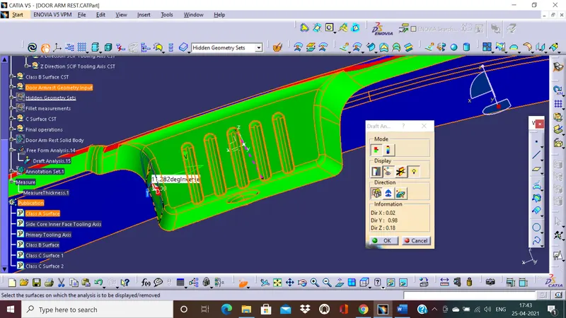
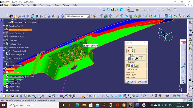
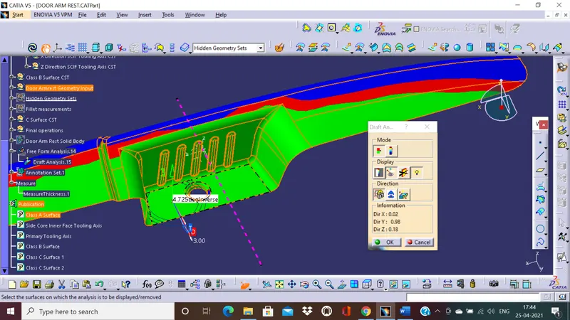
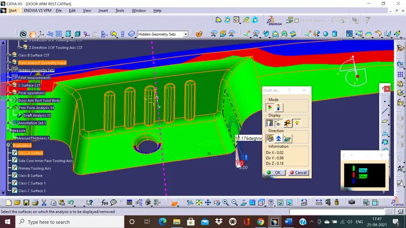
After several manipulations of the Z tooling axis, we have got a side core tooling axis that sufficiently clears all 4 sides of the inner face. The minimum draft angle from the tooling axis is again 3 degrees for the color code to stay green in color.
Final Conclusions of A surface draft analysis:
From the Draft analysis observations, we conclude that-
The A surface component needs to be optimized for a single tooling axis.
If the design cannot be changed, the tooling expense is going to increase as a side core will be needed to create the inner surface. Not only that, the protrusion at the bottom of the component adds more complexity to the molds which would increase expenses.
With increased complexity, the overall costs and also the number of defects may increase.
We must avoid this situation by optimizing the A surface design.
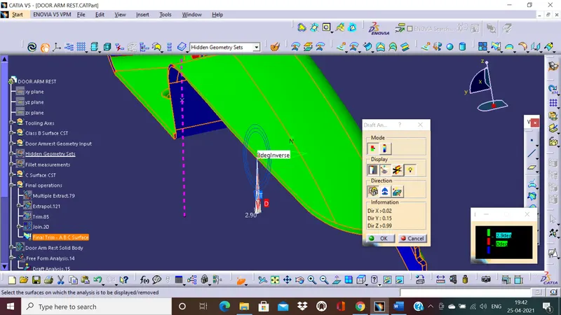
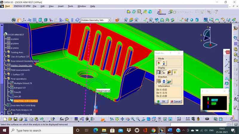
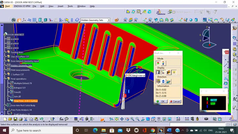
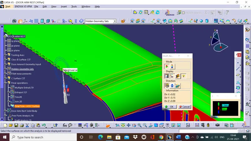
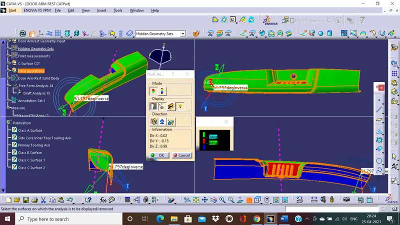
Draft Analysis of the final component:
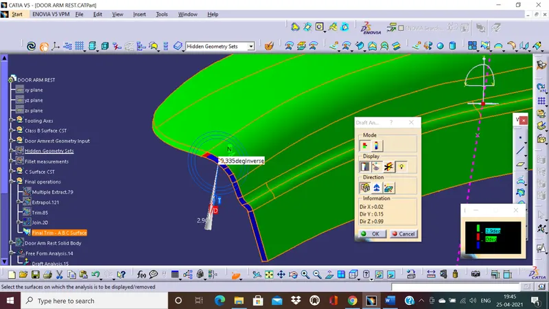
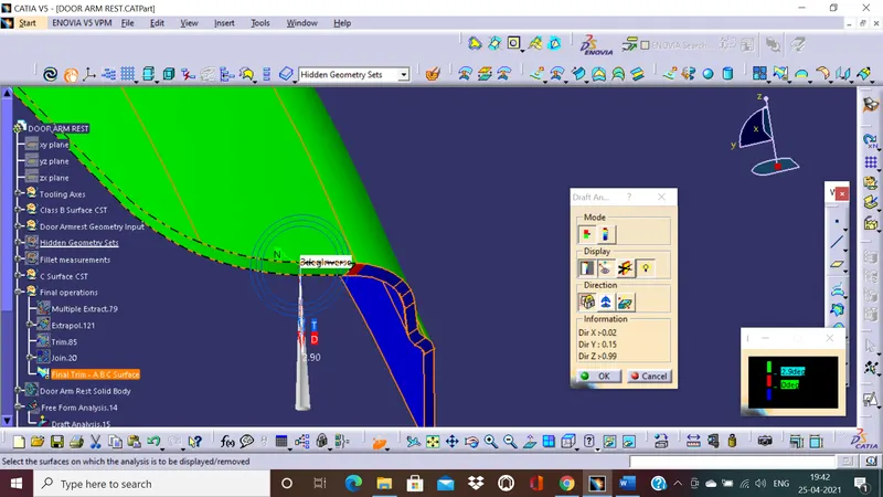
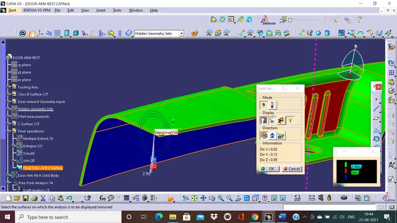
We observe a transition region on the C surface region, this is because the shape of the component is not flat and is curved in a perpendicular direction to the tooling axis.
Side core Draft observations of the component:
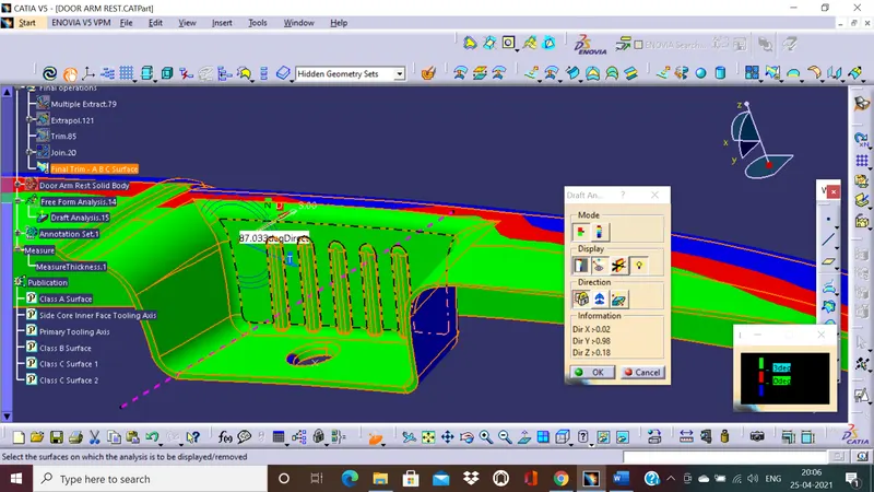
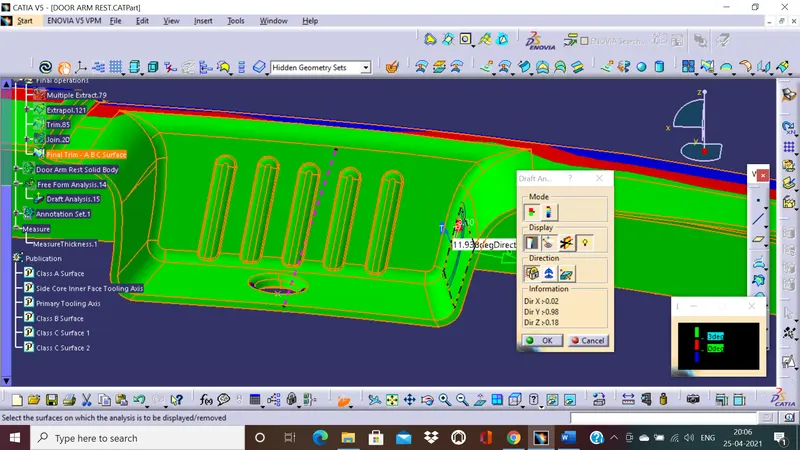
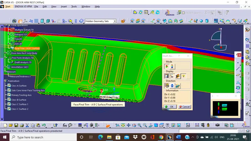
Final conclusions from the draft analysis:
It is observed that there are regions of transition on the C surface. The component is likely to have defects in this region if it is machined using injection molding techniques.
A possible solution that does not modify the Class A surface:
Create another tooling axis perpendicular to the other two tooling axes we have already created.
This is not cost-effective and drastically increases machining costs and defects as well.
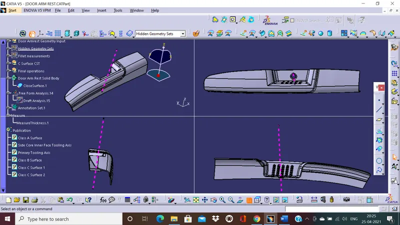
Views of the final component :
Q1:Top view
Q2:Isometric view
Q3:Front view
Q4:Side view
Closed body views:
Q1:Top view
Q2:Isometric view
Q3:Front view
Q4:Side view
Please see the compressed file for the Cat part. Thank you.