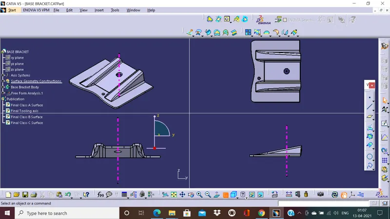
Week 8 - Challenge 2 - Base Bracket Design
For the Class A surface part given, the tooling axis was constructed in the following way.
1. After downloading and opening the part file, check for continuity of the class A surface using the Join operation on all the components provided. I did find an issue with the Class A surface so used the blend operation to join all the surfaces together and create 1 Class A surface. The Boundary operation may then be used to check for any gaps
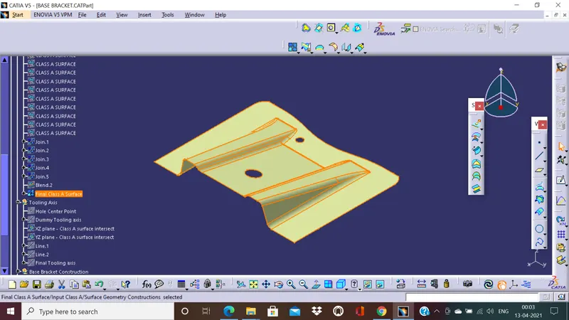
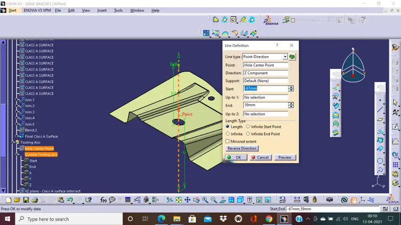
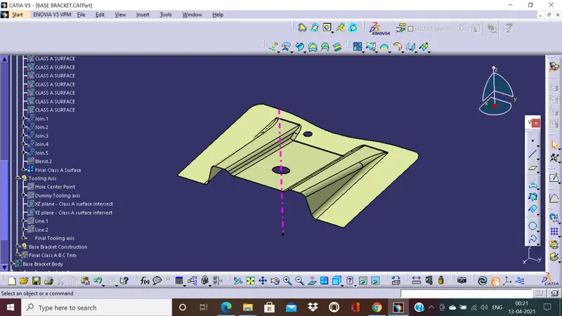
2. I then inspected the surface for the best tooling axis orientation. The holes and ribs do not allow for a single molding axis in two axes as they obstruct ejection in the X and Y-axis directions. The Z-axis does not need side cores and hence would be the least expensive mold to make. So the Z-axis is estimated to be the tooling axis and a dummy tooling axis is created. For this, the Hole center point is created using the hole as the center and along with the Z direction, a dummy tooling axis is made for visualization.
3.Now using the Intersection operation, the Class A surface and YZ plane are used to create the projection of the surface along the YZ plane. The intersection line which is closest to parallel to the Z-axis is extended using two new lines.
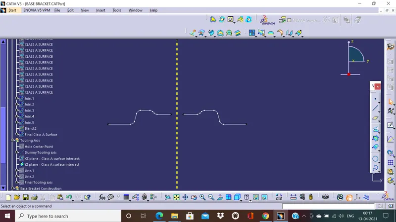
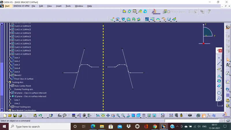
4.Now using these two extended lines, we form the Final tooling axis line by bisecting the two lines and using the Hole Center point.
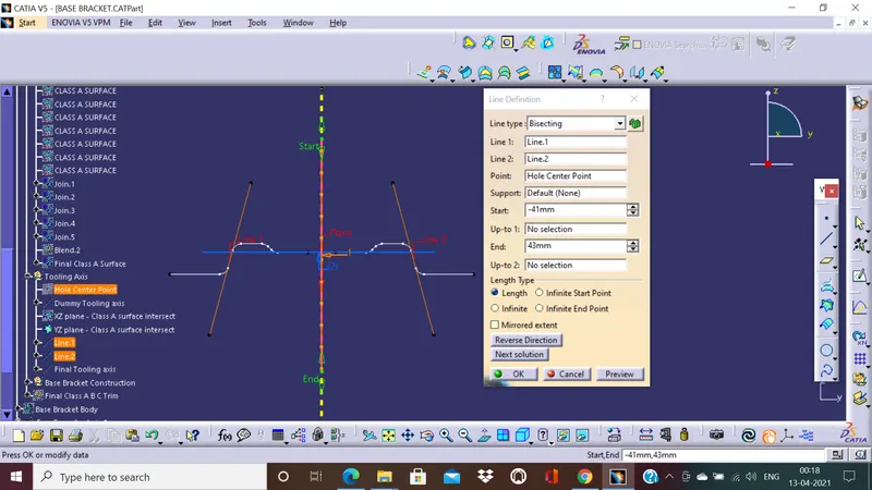
The final tooling axis is thus formed.
Draft analysis of the Class A surface:
Color Range- Draft Degree interpretation:
Green :0 to 3 Degrees; Yellow: 0 to -3 Degrees
Cyan :3 to 20 Degrees;Blue: -3 to -20 Degrees
Red: 20 to 90 Degrees; Red:-20 to -90 Degrees
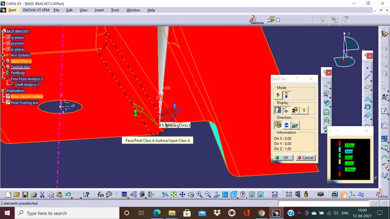
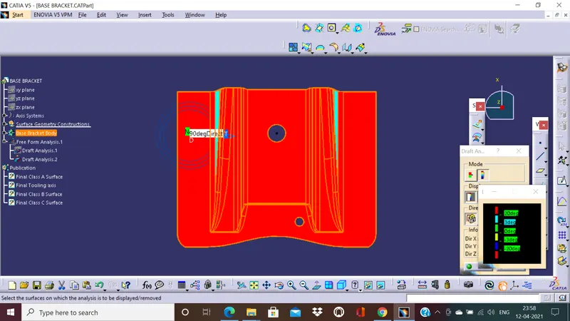
At the flat base, the draft angle is 90 degrees as shown below by the running point.
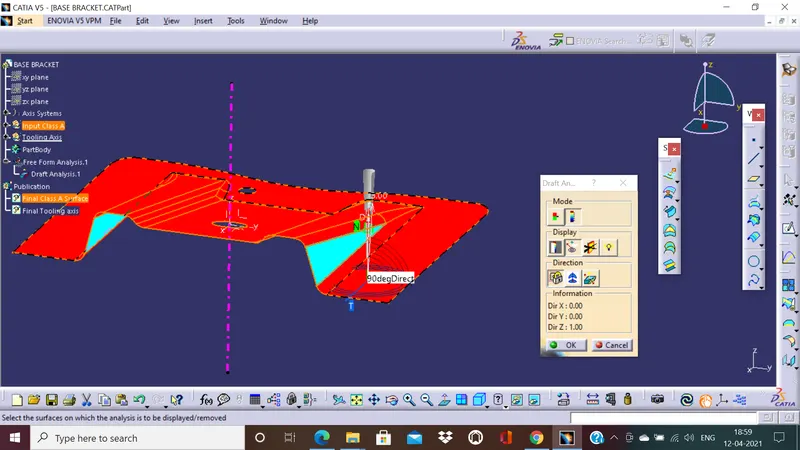
Near the fillet, the angle decreases to 43.582 ~ 43 degrees.
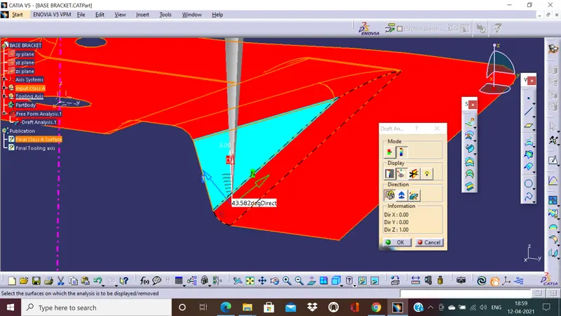
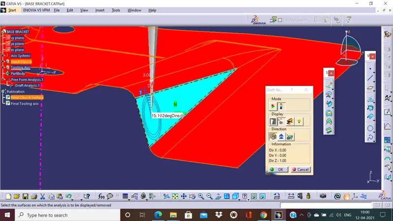
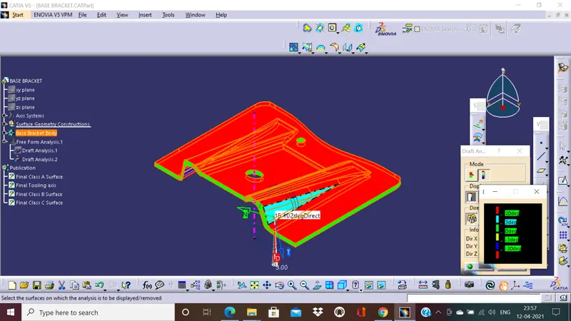
At the ribs which are closest to 0 degrees to the tooling axis, the draft angle is 15 degrees and is cyan color.
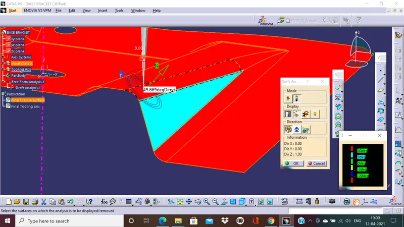
At the top fillet, the draft angle is around 50 degrees and is in red color.
On the other side, the top fillet is at 61 degrees.
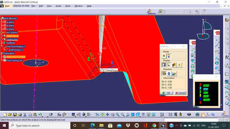
The lower fillet is at an angle of 43 degrees and poses no issue to molding
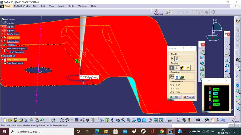
The top angled face is almost perpendicular to the tooling axis and is approximately 80 degrees.
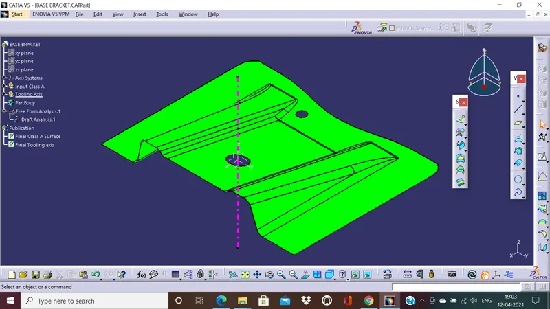
The class A draft analysis is complete and since the minimum draft angle for the machine is 3 degrees, the class A surface can be injection molded without issues because of the draft angle. 15 degrees is the least draft angle recorded on the part.
Draft analysis of the solid part:
After constructing the Class B and Class C surfaces, the solid body part created and analyzed.
The minimum Draft angle set is 3 degrees while creating the solid body.
This is clearly seen in the draft analyser; All the edges are green in color and measure 3 degrees as designed.
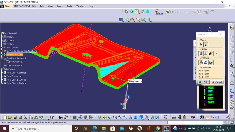
The flat face in red is at 90 degrees.
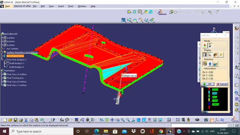
The outer rib area has a draft angle of 15 degrees whereas the inner draft angle is between -13 and -14 degrees.
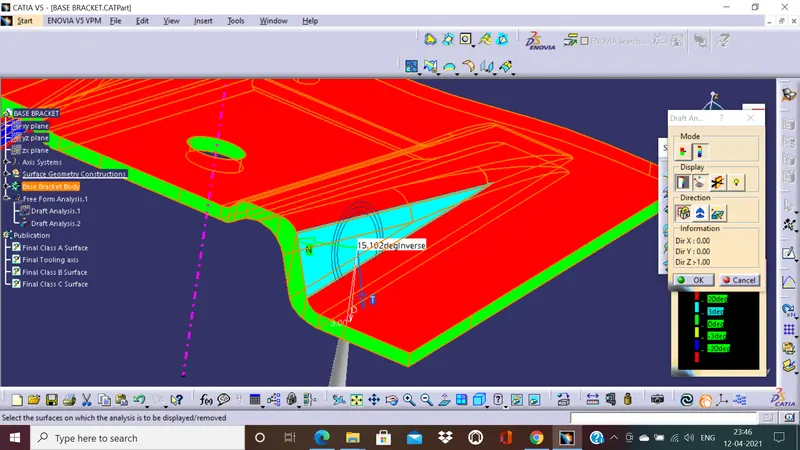
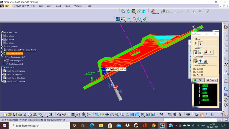
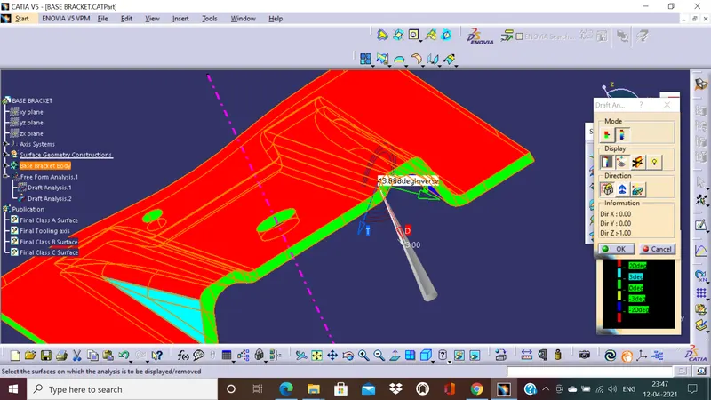
The top inner fillet is at 38 degrees.
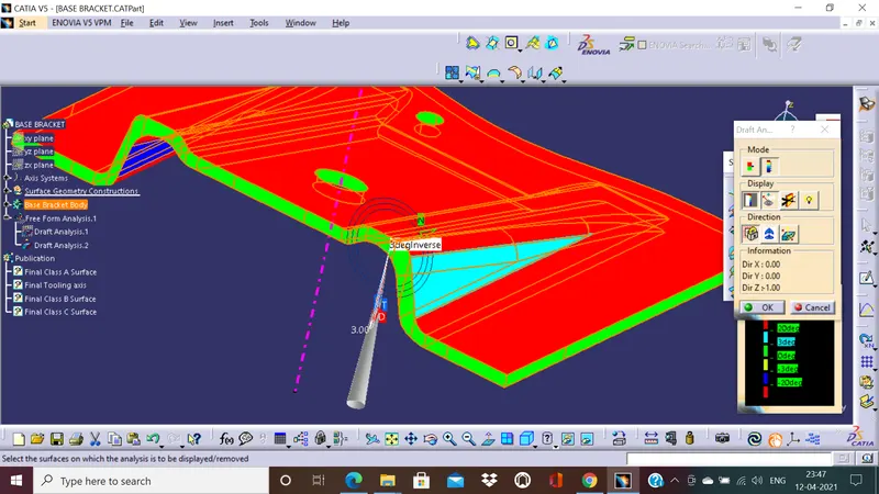
Inner edge fillet is recorded at 55 degrees.
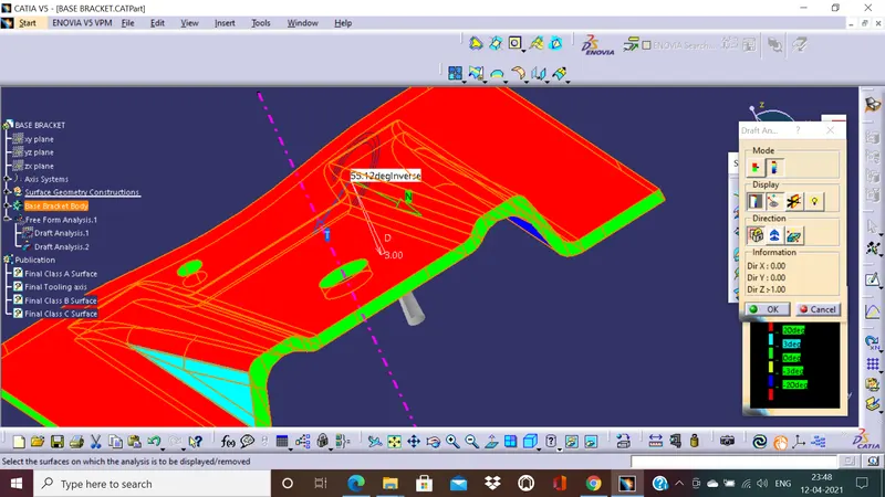
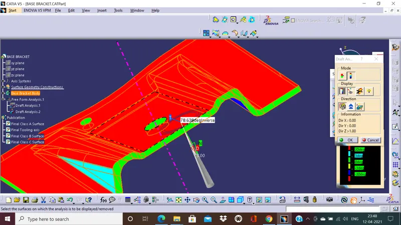
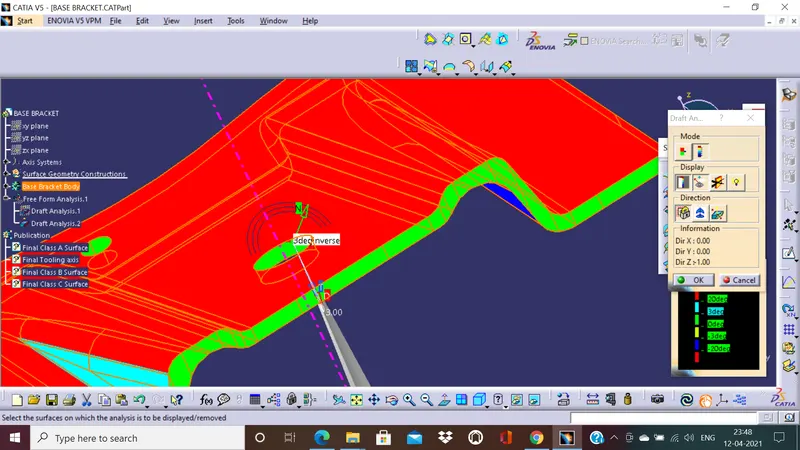
The 3degree edges around the boundary and the holes may be an issue. However, the part is designed within the required specifications.
Top View
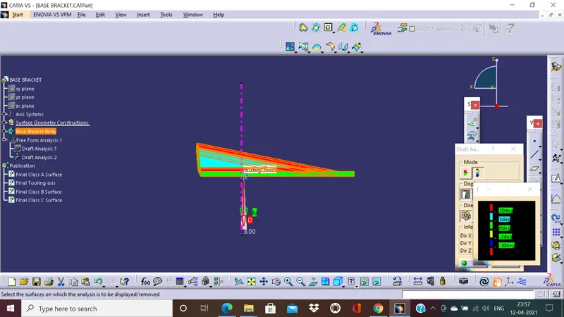
Side view
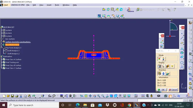
Front view
Isometric view
Quadrant views:
Q1: Top view
Q2:Isometric view
Q3:Front view
Q4:Side view