Week 9 - Project - Master Section Development
REPORT ON B PILLAR
We had class A surface and master sections. first checked continuty of surfaces if some patches or unimproved surfaces found then improve it.
TOOLING AXIS
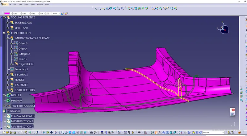
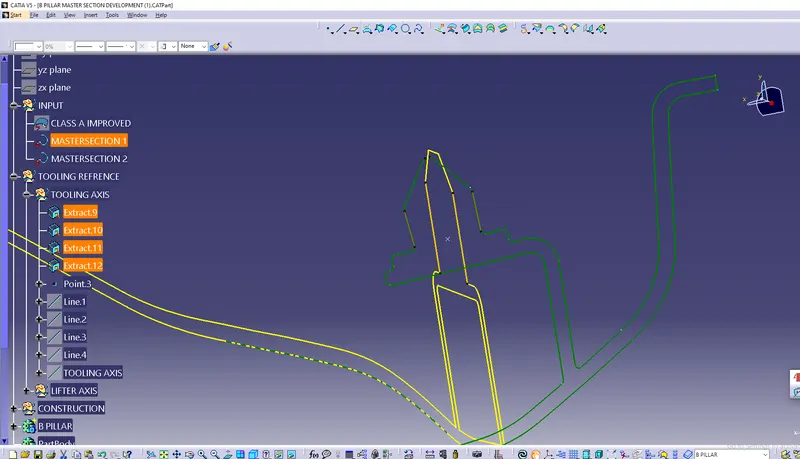
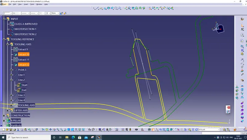
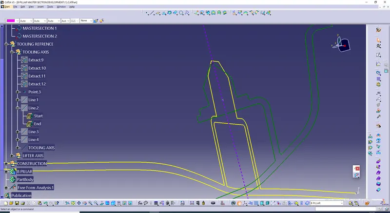
1) With the help of master sections extracted four lines of master sections. created mid point with any two lines and by bisecting line option created first bisecting line similarly created other bisecting line. finally getted tooling axis with help of two lines by bisecting option.
LIFTER AXIS
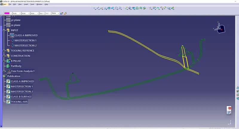
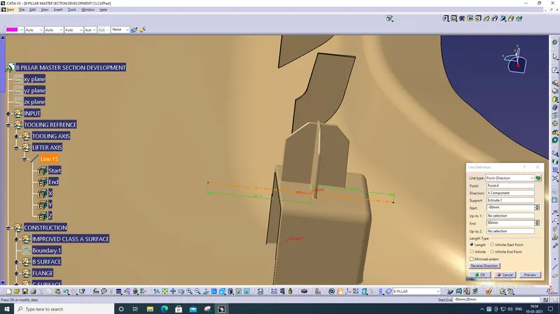
1) Lifter axis was used in inside drafting of dog house with 4 way locator. for lifter axis just created line in X direction through point on dog house surface.
B SURFACE
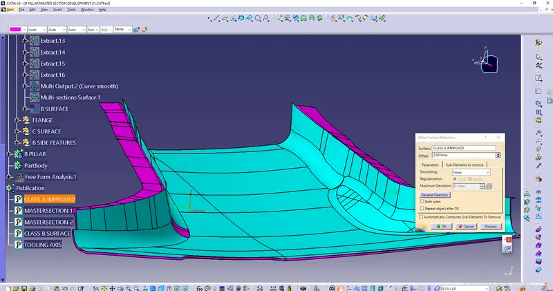
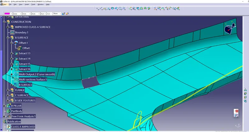
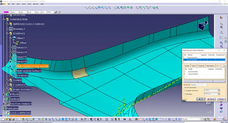
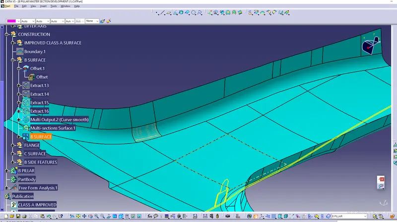
1) To created B surface offseted improved class A surface with 2 mm. here geted hollow patch solved it locally extracted all boundries of patch and filled that area with multisection surface and joined that patch with offseted surface.
FLANGES
FLANGE 1
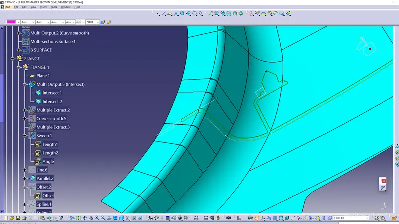
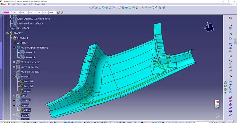
1) For flanges took plane with help of master section and gave intersection.
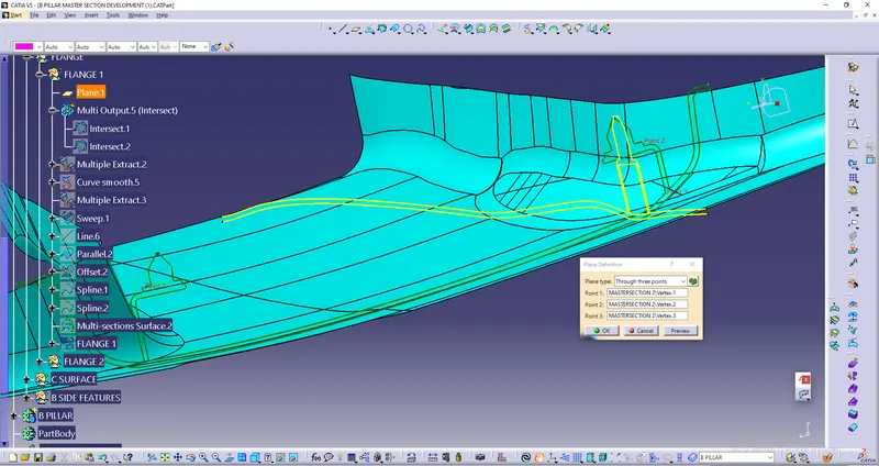
2) Extracted edge of class A surface and gave smooth curve to it. extracted class A surfaces, sweeped it in tooling dirction and gave draft angle of 5 degree and tried to joined with master scetion.
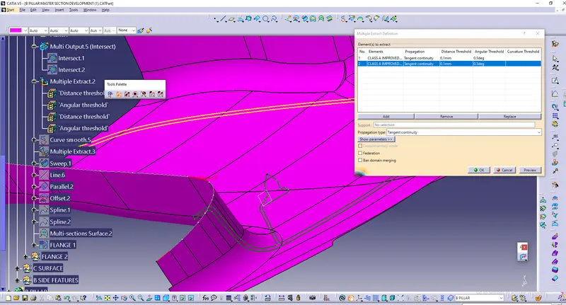
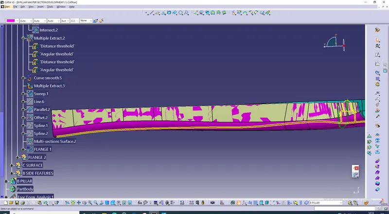
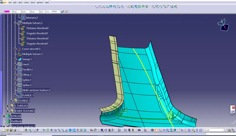
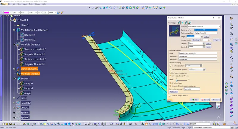
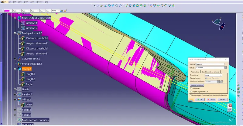
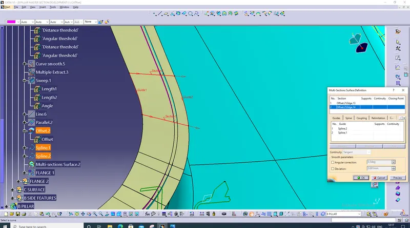
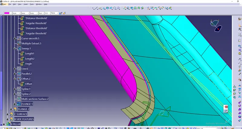
3) Offsetted that sweep to dimension measured from master section. here also getted hollow patch resolved it by created splines over it and filled it by multisection surfaces tool and joined with offseted surface.
FLANGE 2
1) Similarly here also extracted edge and surface, sweeped it in tooling direction and gave draft angle of 5 degree to it. offseted it and improved patch with spline and master section tooltried to match master section.
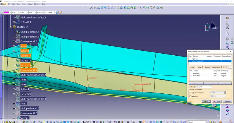
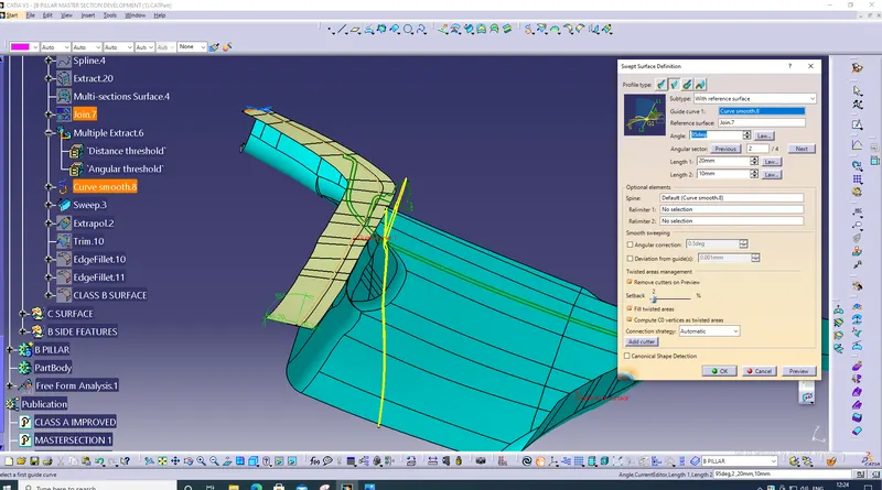
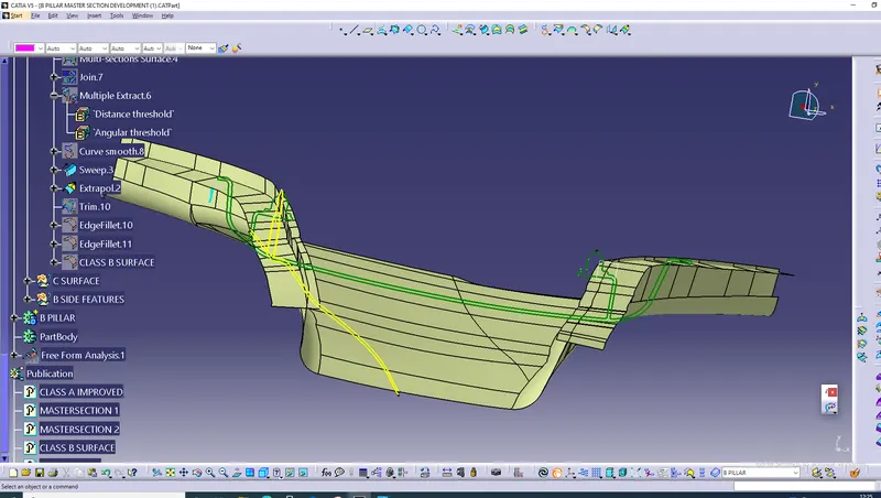
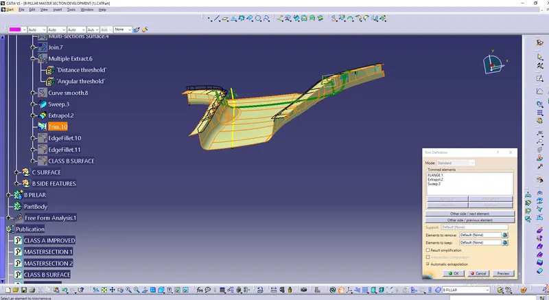
2) Finally trimed both flanges and getted B surface.
C SURFACE
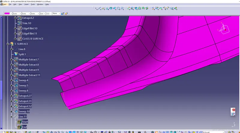
1) Removed that unwanted surface just created line and splited it. multiple extracted all four edges of boundry and sweeped it.
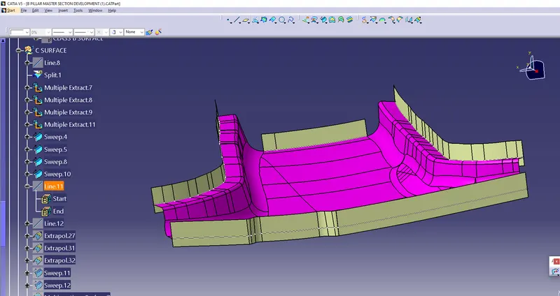
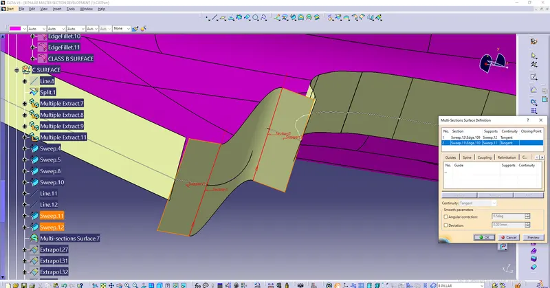
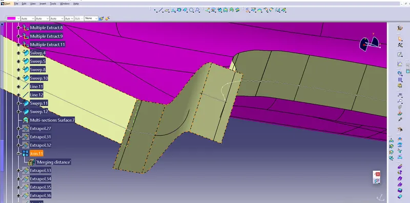
2) For this remained part created two lines over showned edges and sweeped it in tooling direction and filled area with master section tool further joined it with sweep.
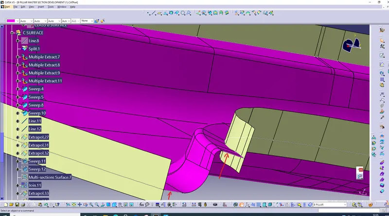
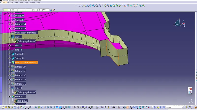
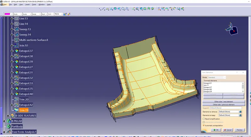
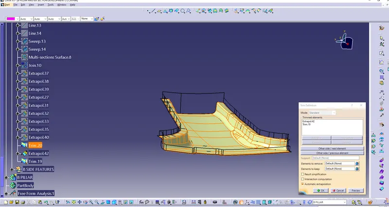
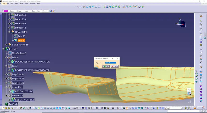
3) Extrapolateed all surfaces that was not intersected and finally trimed all unwanted part. after that getted thickened surface.
B SIDE FEATURES
DOG HOUSE
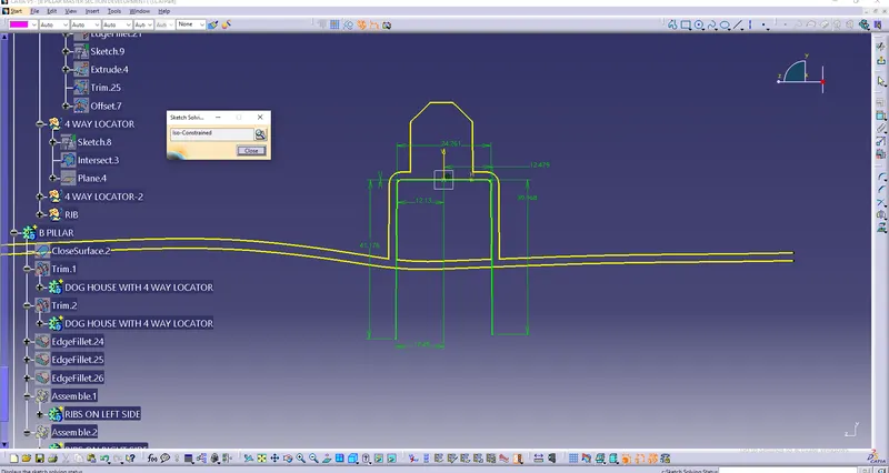
1) Took ponit and plane over master section and projected master section and drew sketch for dog house. extruded the sketch further drew line over master section it was nothing but limit for dog house
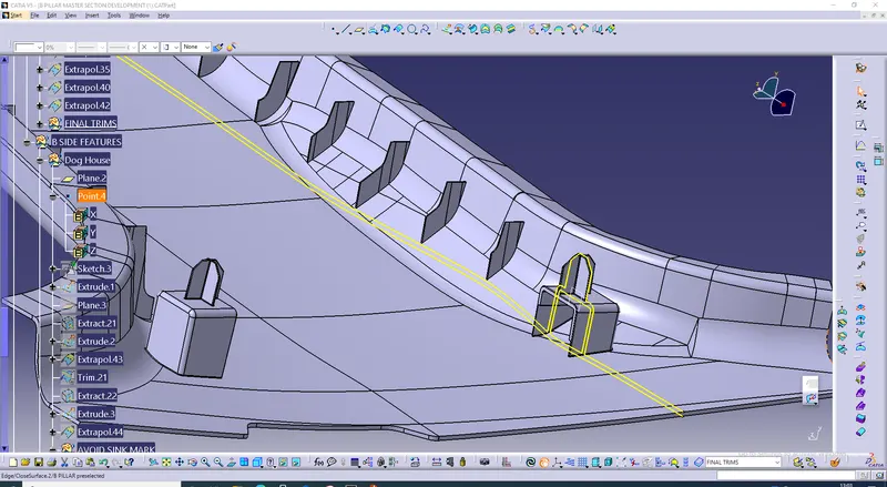
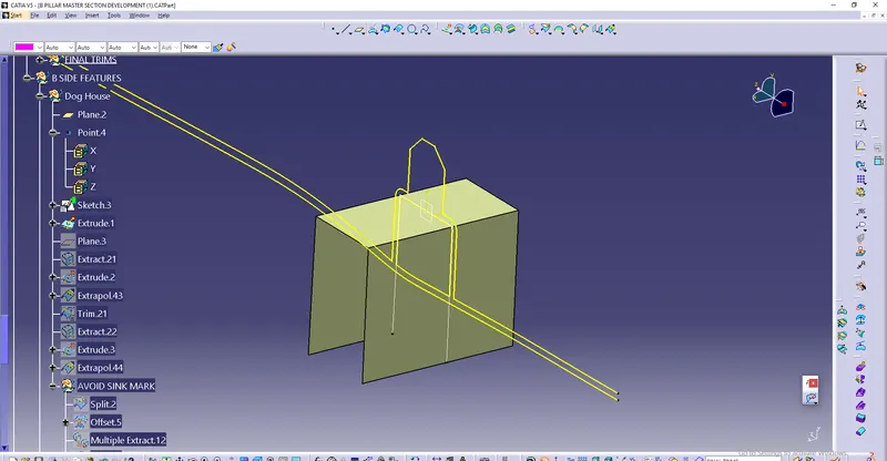
2) Extruded and extrapolated that line further trimed unwanted part.
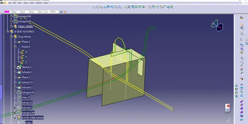
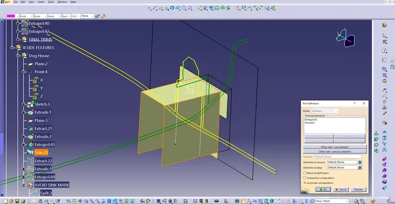
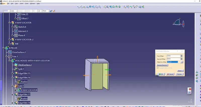
3) Splited front limit with remaining part and getted dog house shape.
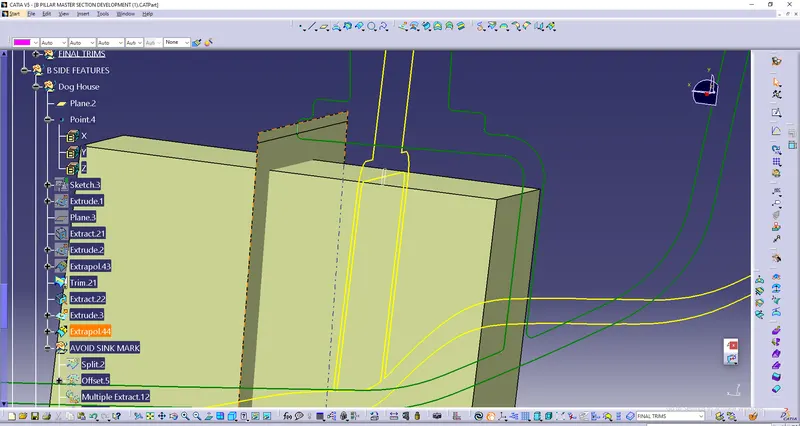
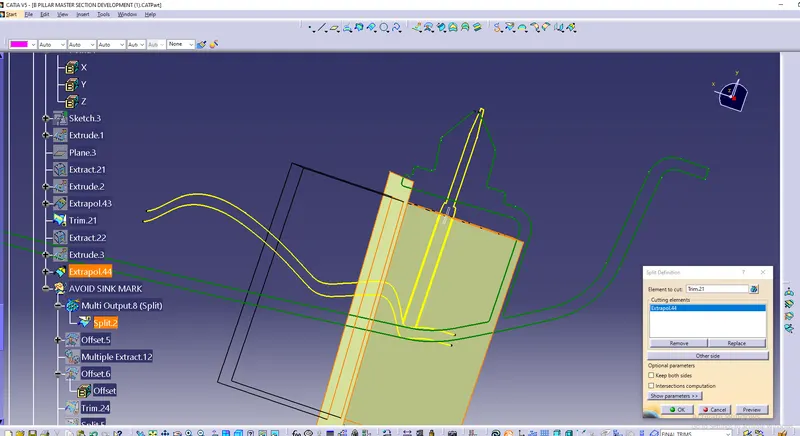
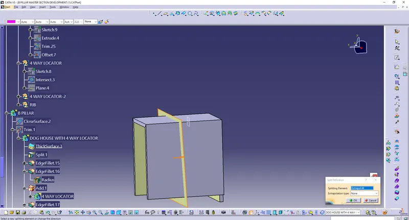
4) For under cut in dog house extracted b surface took intersection inside dog house and projected it. further drew sketch for it and extruded
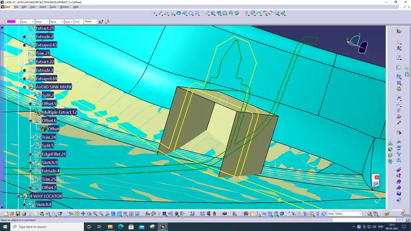
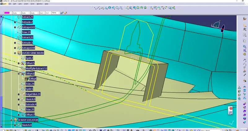
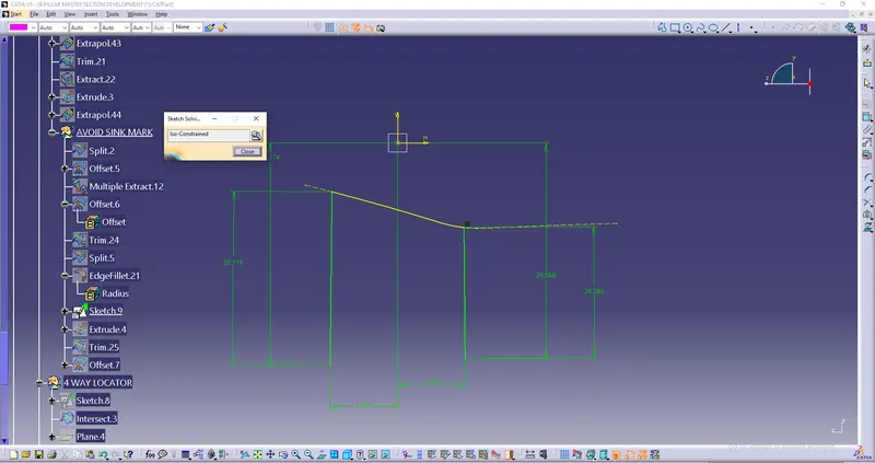
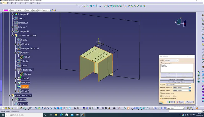
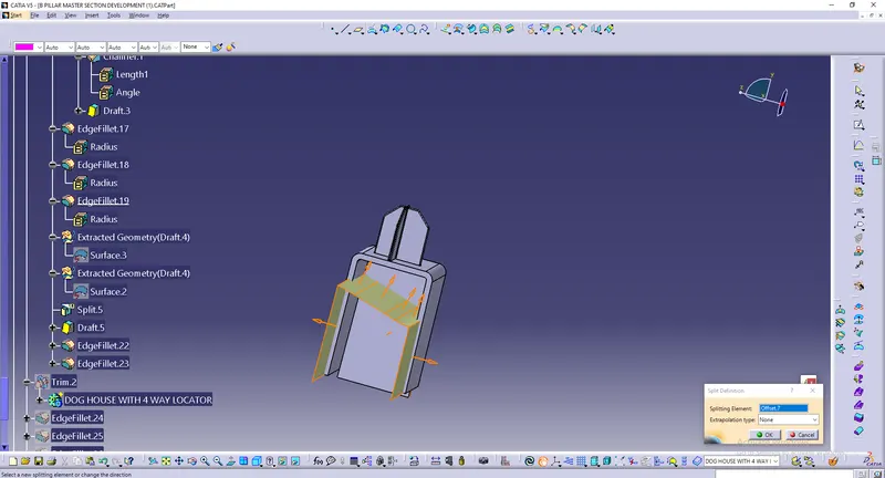
5) Trimed that extrude with back limit and splited it in part workbench.
4 WAY LOCATOR
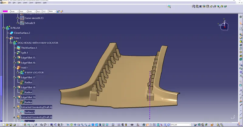
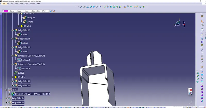
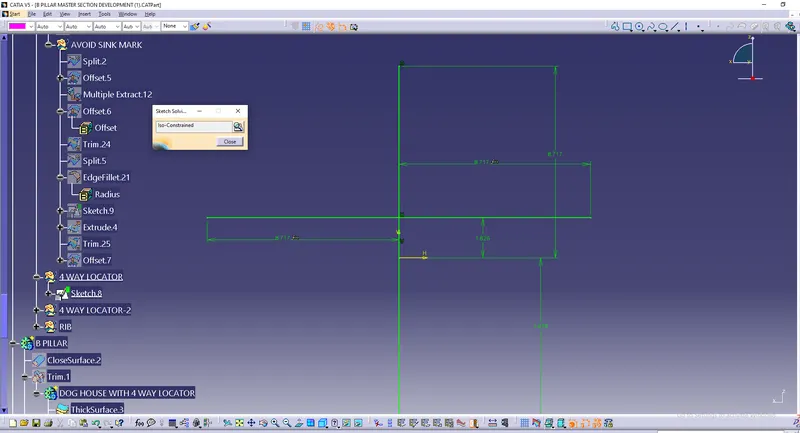
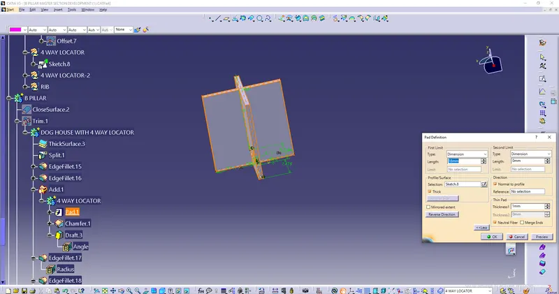
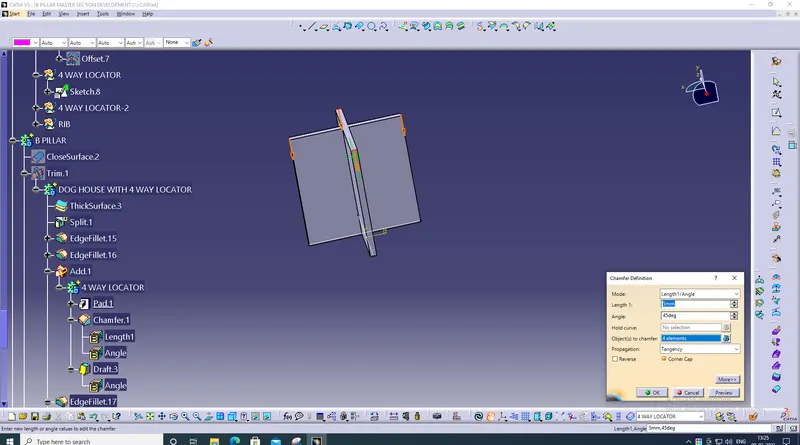
1) Drew sketch for 4 way locator and paded it. gave 5mm chamfer to it and drafted with 0.5 degree angle. further added to dog house body
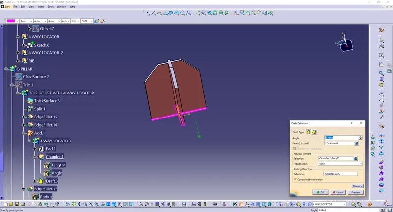
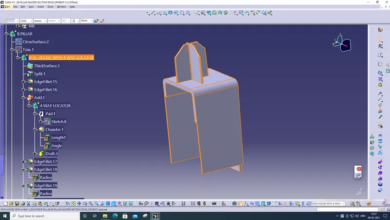
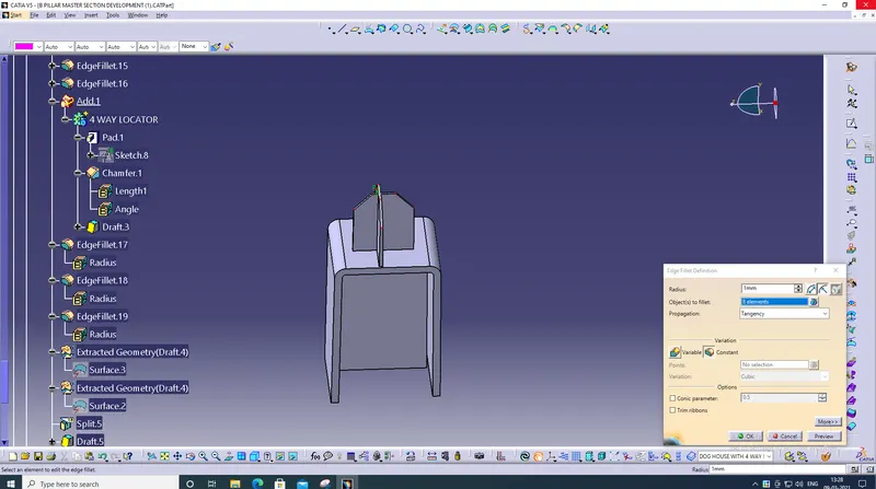
2) Gave draft of 0.5 degree inside the dog house and edgefillet to undercut.
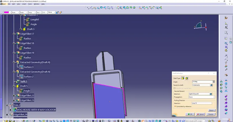
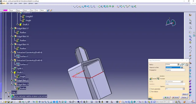
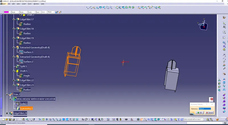
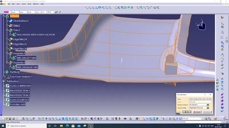
3) Offseted plane and translated hole dog house with 4 way locator body to otherside and added it to B pilar body.
RIBS
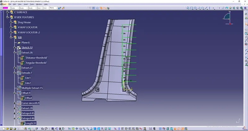
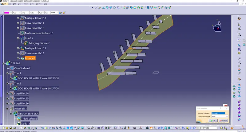
1) Created plane over B pillar and drew sketch for ribs. extruded lines in sketches and thickened it.
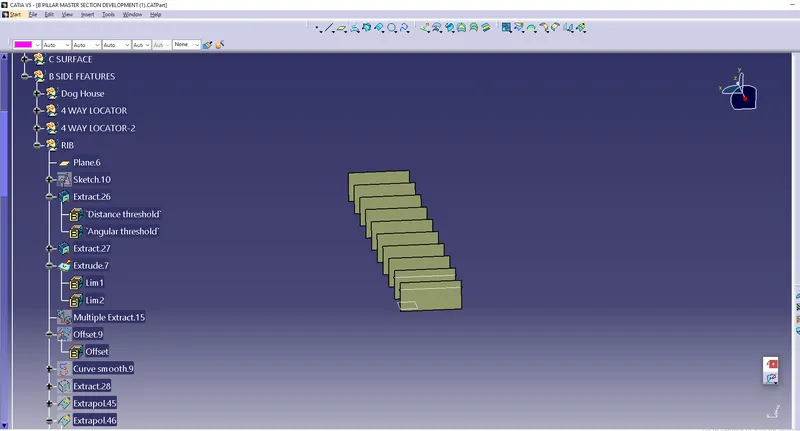
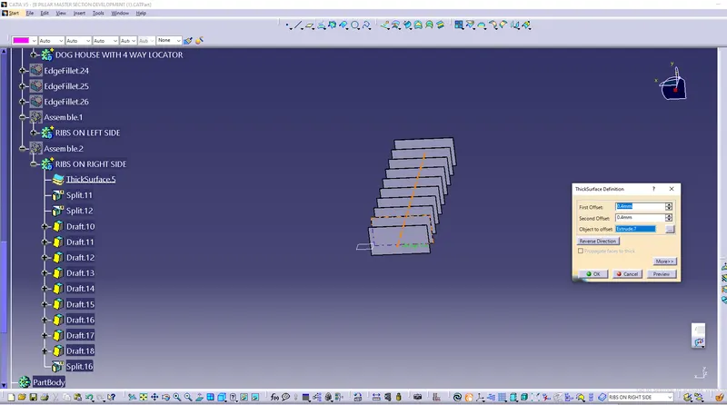
2) Extracted B surface and splited it in part workbench further offseted the B surface and again splited it with recently getted split to get desired rib shape.
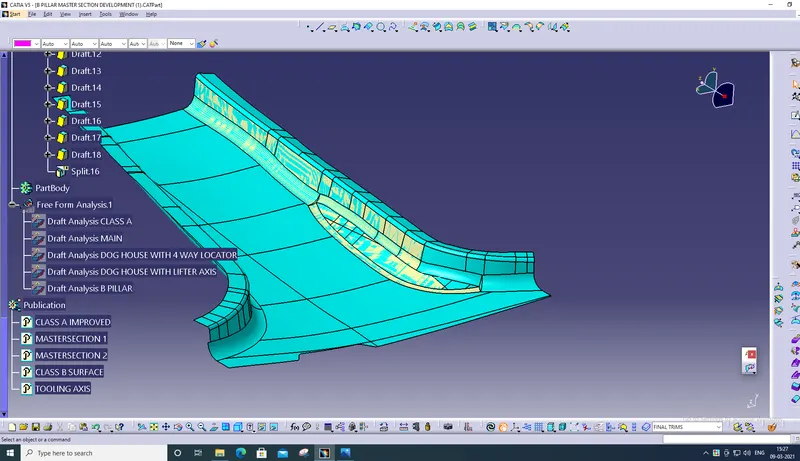
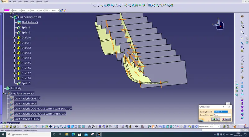
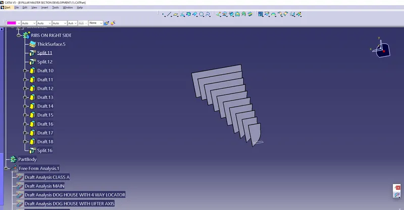
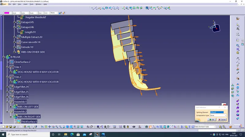
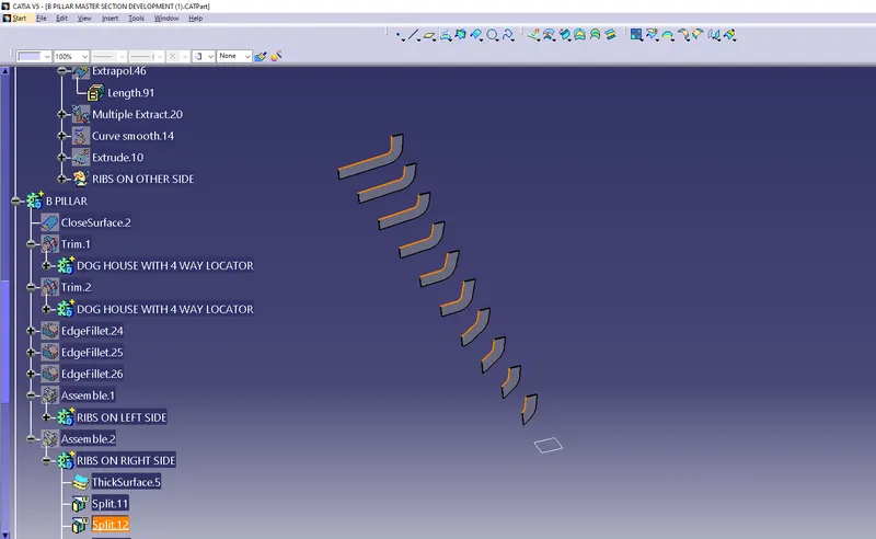
3) Similarly on other side drew sketches and extruded it. further thickened it and splited in part workbench with extracted B surface.
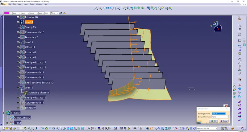
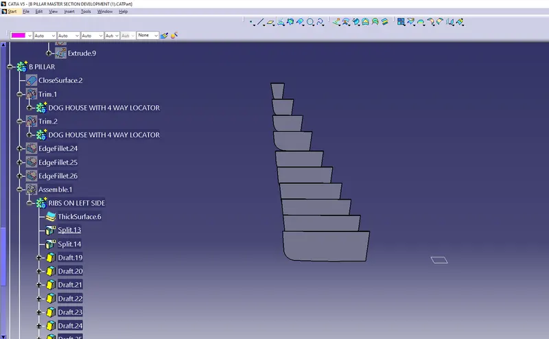
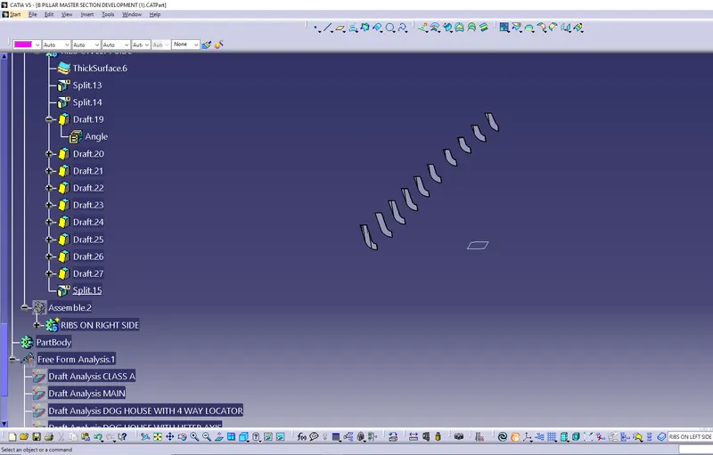
4) Offseted the B surface and splited with recently getted split and drafted both sides ribs with 0.5 degree angle.
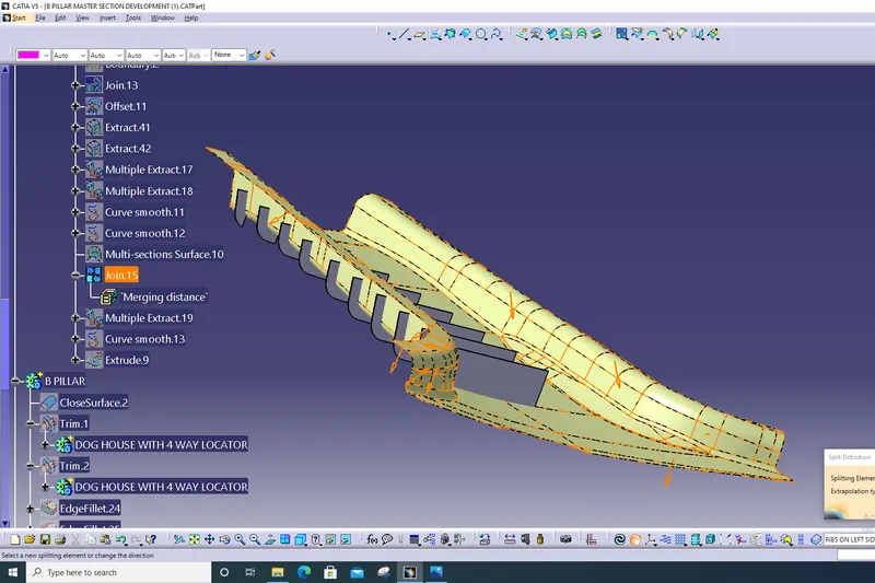
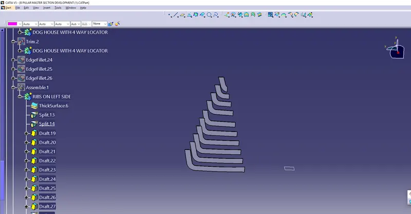
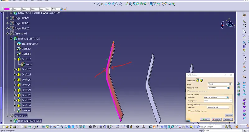
5) For appropriate shape of ribs multiple extracted showned edge and extruded it. further splited it with extruded surface in part workbench and added this ribs to B pillar main body.
DRAFT ANALYSIS
DRAFT ANALYSIS OF CLASS A
1) We had tooling axis checked whether was customized view mode or not and material mode was selected. whole class A surface was showed green and every point over showned draft angle greater than 3 degree.
DRAFT ANALYSIS OF PLASTIC BODY
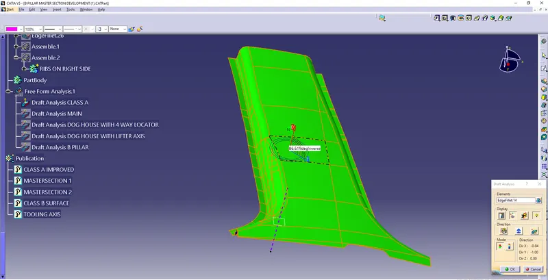
1) Here also upper side of body was showned green and each point over it was showned grater than 3 degree means draft was correct.
2) All edgeside surfaceswas showned blue because during sweep we drafted it with 0.5 degree angle. hence it showed 0.5 degree of angle over each point on all edgeside surfaces.
DRAFT ANALYSIAS OF DOG HOUSE WITH WAY LOCATOR WITH TOOLING AXIS
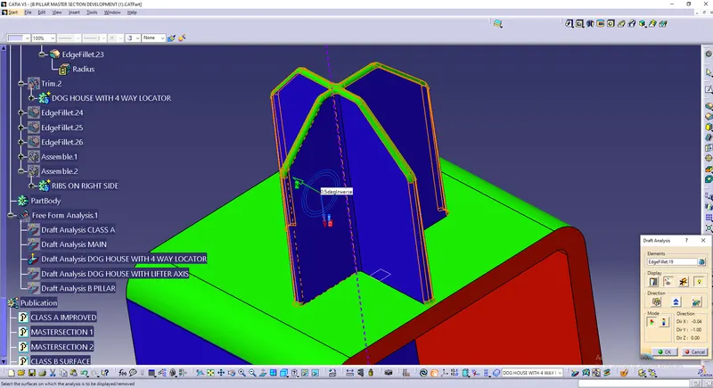
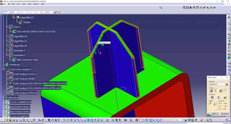
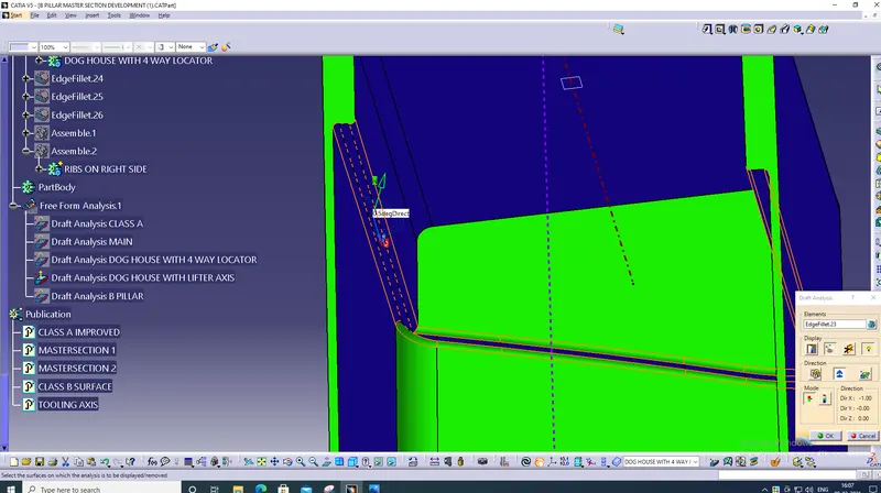
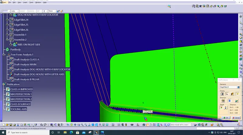
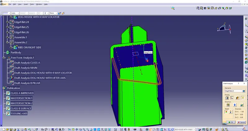
1) After draged compass over tooling axis and locked direction different colour variant showned over surfaces. considered outside surfaces of dog house with 4 way locator, all surfaces showned by blue and green colour means draft was coorect. Side surface of dog house was showned blue colour with 0.4 degree draft angle.
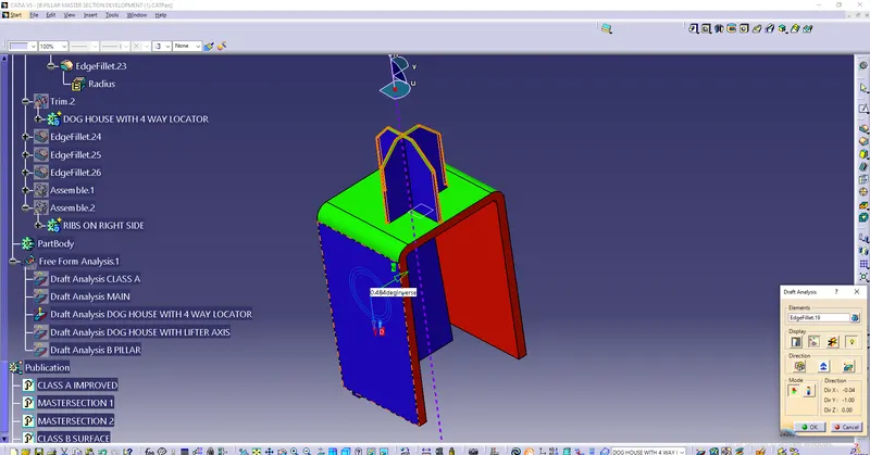
2) Outer surface of 4 way locator was showned blue colour because we drafted it by 0.5 degree and edgefilleted surface of 4 way locator was showned green colour with 44.156 degree draft angle.
DRAFT ANALYSIS OF DOG HOUSE WITH WAY LOCATOR WITH LIFTER AXIS
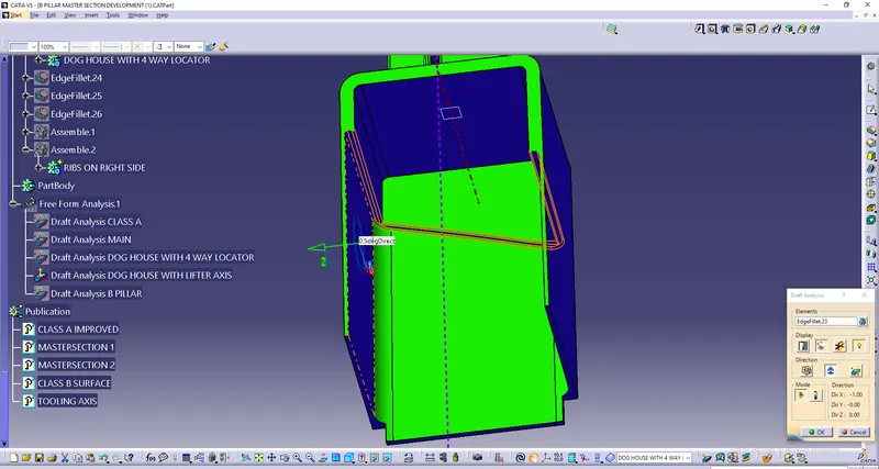
1) For inside draft of dog house used lifter axis. here also after draging of compass over lifter axis different colour variant showned over surfaces. considered inside surfaces and inside base surface showned green with 90 degree draft angle because it was flat surface.
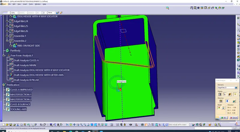
2) Side surfaces of inside dog house was showned blue colour because we drafted it by 0.5 degree draft angle. all undercuts was showned blue it also drafted by 0.5 degree draft angle.
DRAFT ANALYSIS OF B PILLAR
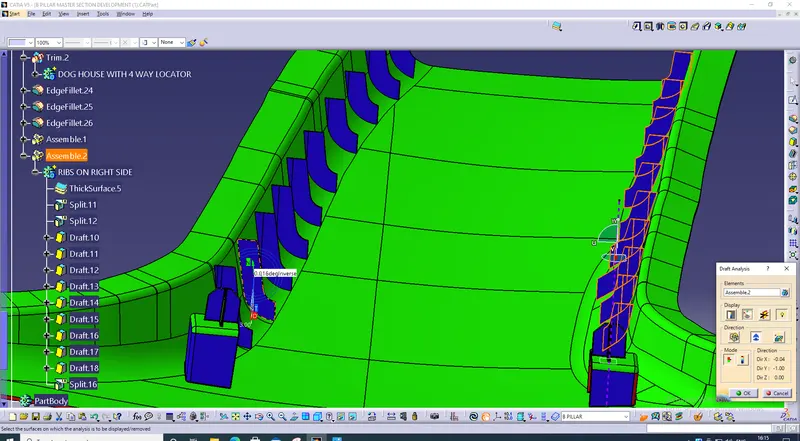
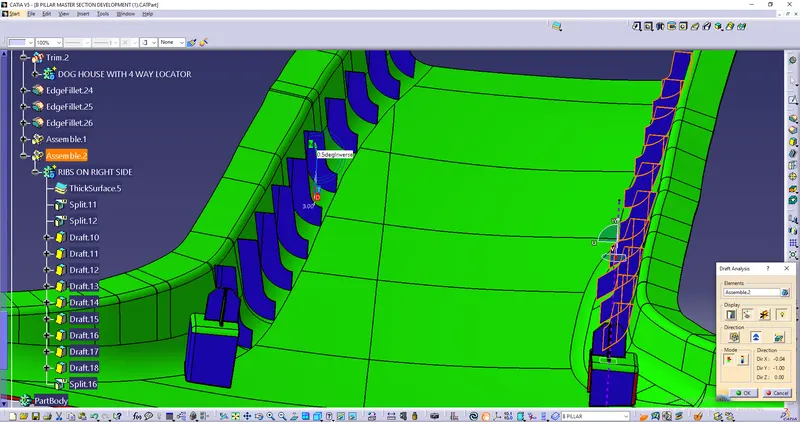
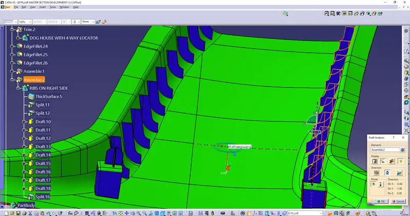
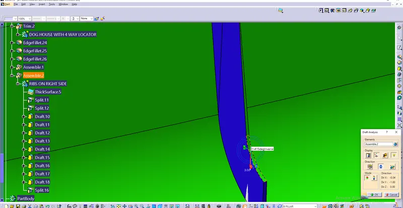
1) For draft analysis of final B Pillar body draged compass over tooling axis and locked direction. considered inside of B pillar where dog house with 4 way locator and ribs are located for draft analysis. all surfaces was showned blue and green colour means draft was correct.
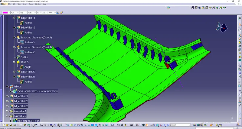
2) All outsides of dog house with 4 way locator and ribs showned by blue colour because we drafted it by 0.5 degree angle and other Flat sides was showned green had draft angle more than 3 degree.
FINAL B PILLAR COMPONENT