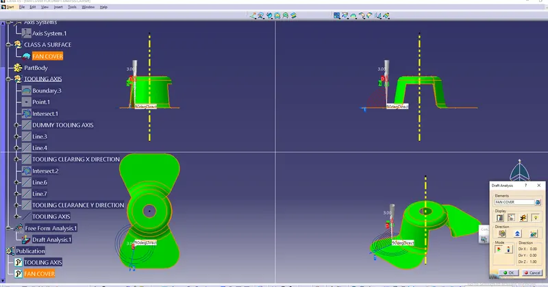
Week 8 - Challenge 1 - Draft Analysis on a Fan Cover
DRAFT ANALYSIS
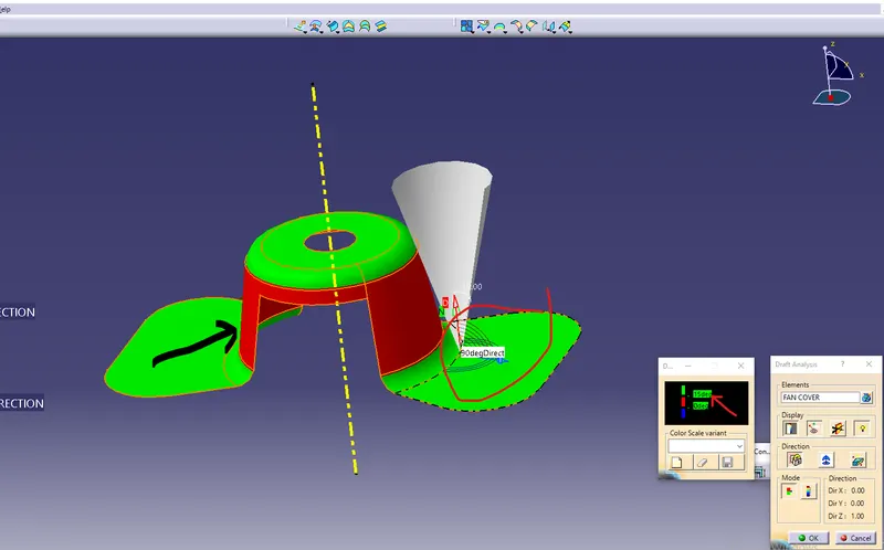
It is command which enables you to detect if the part you drafted will be easily removed. This type of analysis is performed based on color ranges identifying the zones on the analyzed element where the deviation from the draft direction at any point cooresponds to specified values.
WHILE DRAFTING FOLLOWING STEPS TO BE PERFORMED
1) CHECK CONTINUITY
First of all check whether there is no gap between two surfaces.
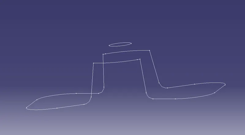
2) FIND TOOLING AXIS
Tooling axis is the direction in which mould pulls apart in injection molding.
1) Check all best possible tooling directions.check x,y & z directions
In X axis upper hole is not visible and its creates complications
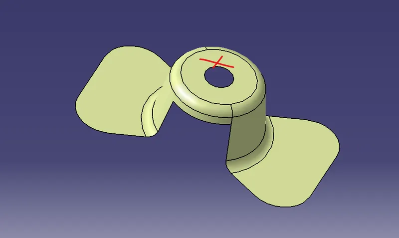
In Y direction upper hole and backside so we have to creat there side core its increaes the cost
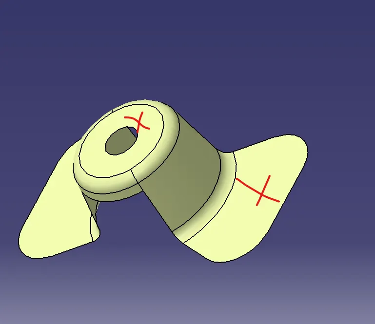
In Z directions All are visible and there is not required side core
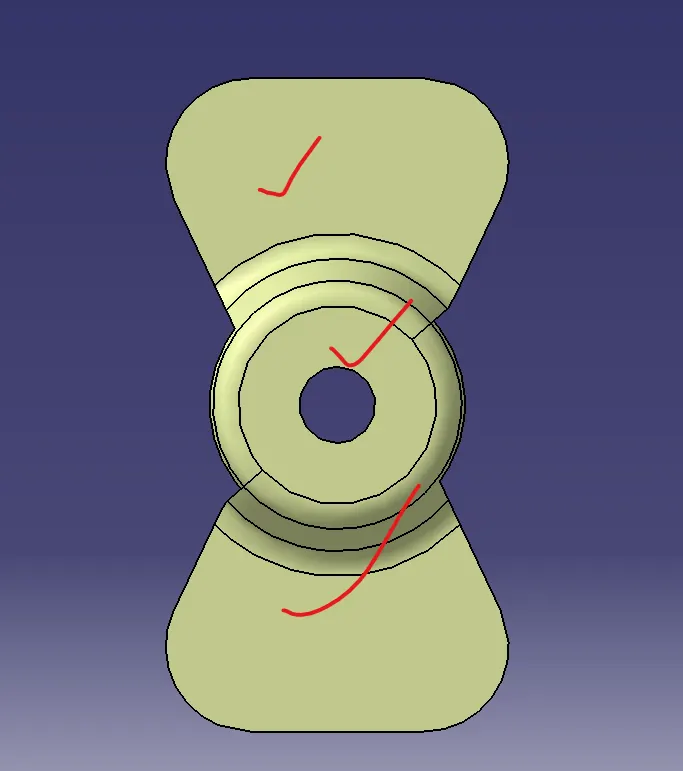
2) Creates geometrical set and create point and inserts axis system on it and take ZX plane and intersects with surface.
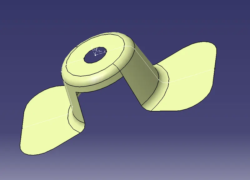
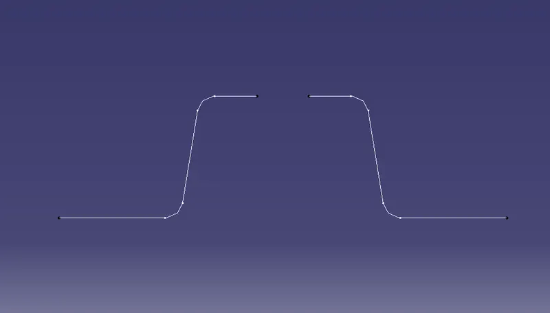
Creates dummy axis along Z axis through pt. Then creates lines point to point direction. Then create bisecting line from recently getting two lines and point and we get tooling clearing in X direction
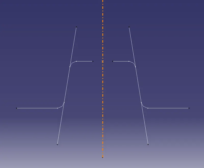
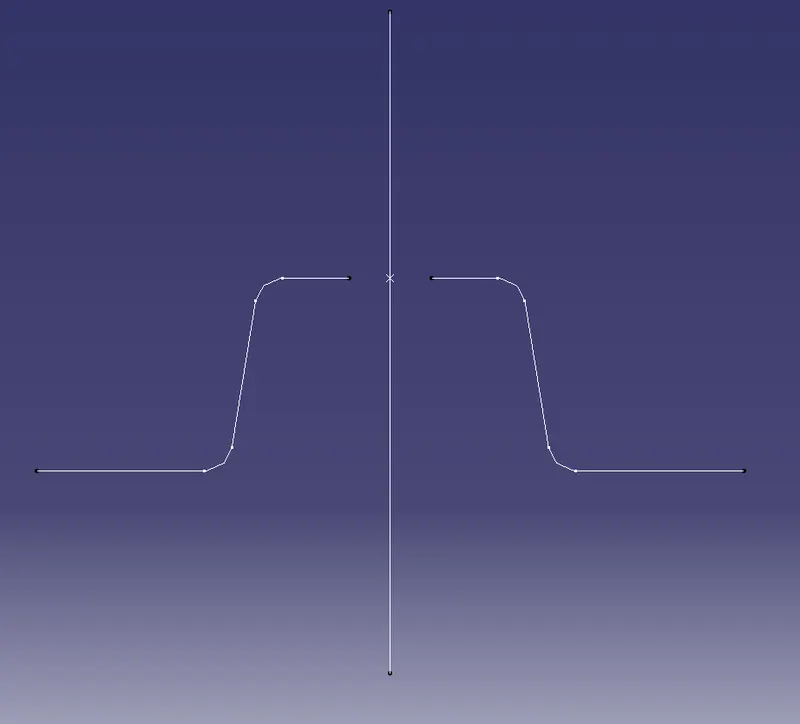
Similarly creates tooling clearing in Y direction
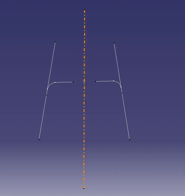
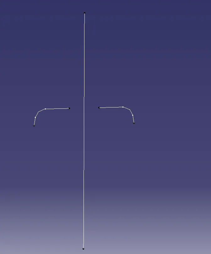
And again using bisecting line get tooling axis
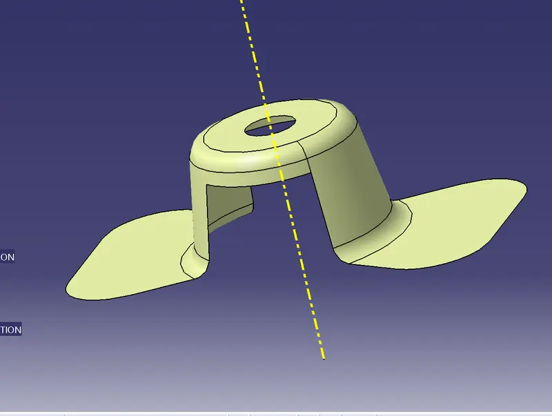
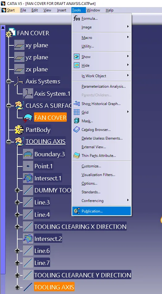
3) Published the tool axis and fan cover
It is a save copy of required componenets.
Select those want to published. Go to tools there is publication command and published it.
4) Find draft analysis
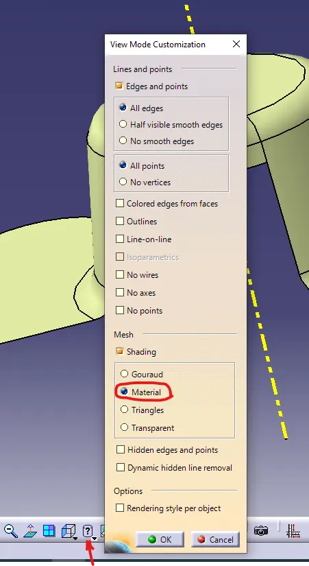
Go to view mode customization and check whether material is selected or not.
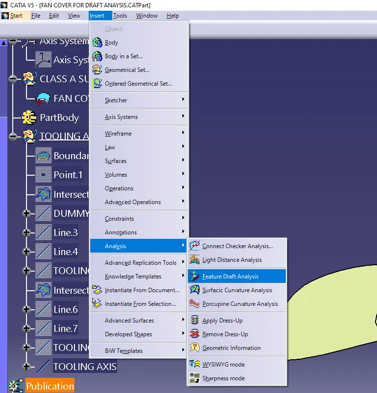
Then go to insert then analysis and further go to feature draft analysis
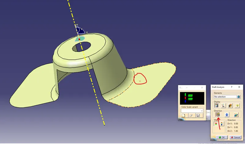
Use compass to defined new current draft direction. drag the compass with the help red dot on tooling axis.
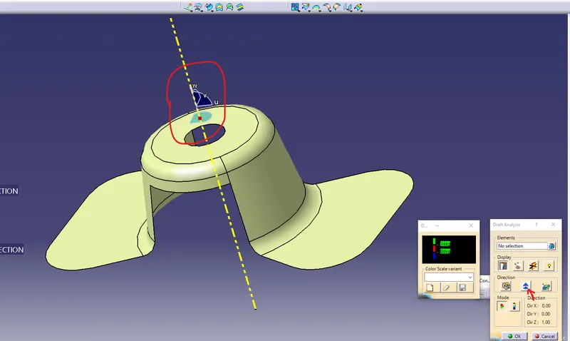
Then go to direction and select lock and red cross is display on surface. then click on surface and color of part will be change.
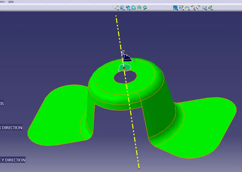
after go to running point draft angle will be showing there.
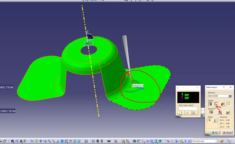
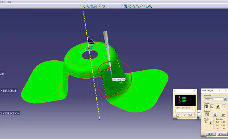
Different views of Part