Week 8 - Challenge 2 - Base Bracket Design
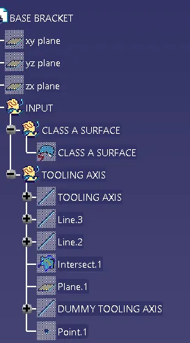
TOOLING AXIS
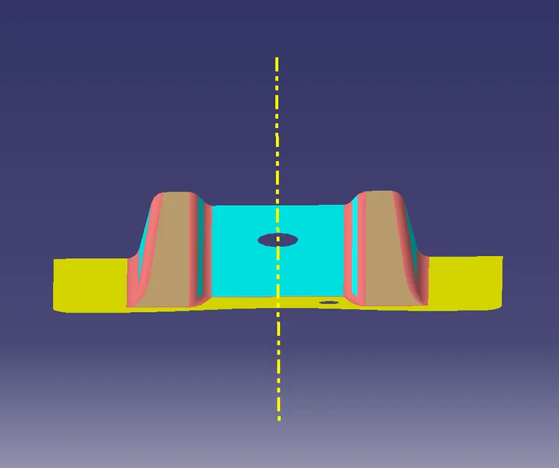
1) To find tooling axis first of all checked whether there is no gap between two surfaces.
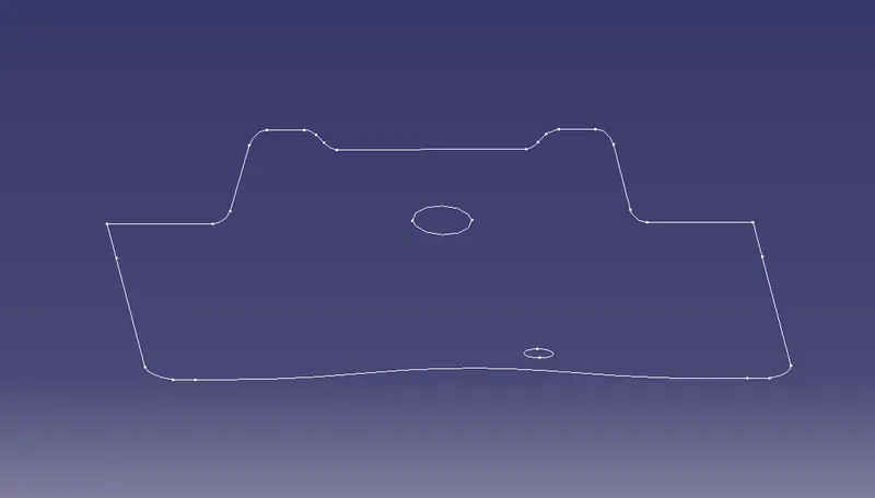
2) Checked all possible directions to getting tooling axis. checked all X,Y,Z direction and checked in which direction covers all surfaces.
3) In X direction backside hole was not visible.
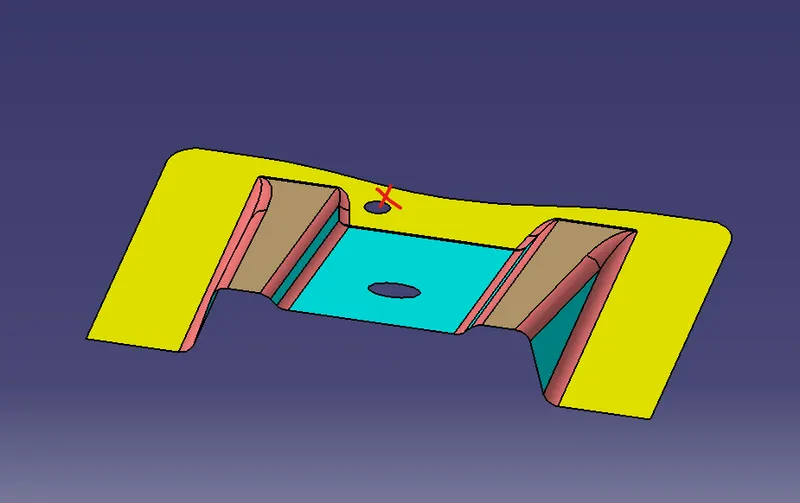
4) In y direction slant surface with hole, outer surface with small hole and one of the rib was not visible.
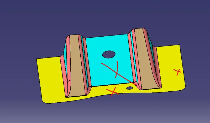
5) But In Z direction all surfaces and hole is covered. So take Z direction
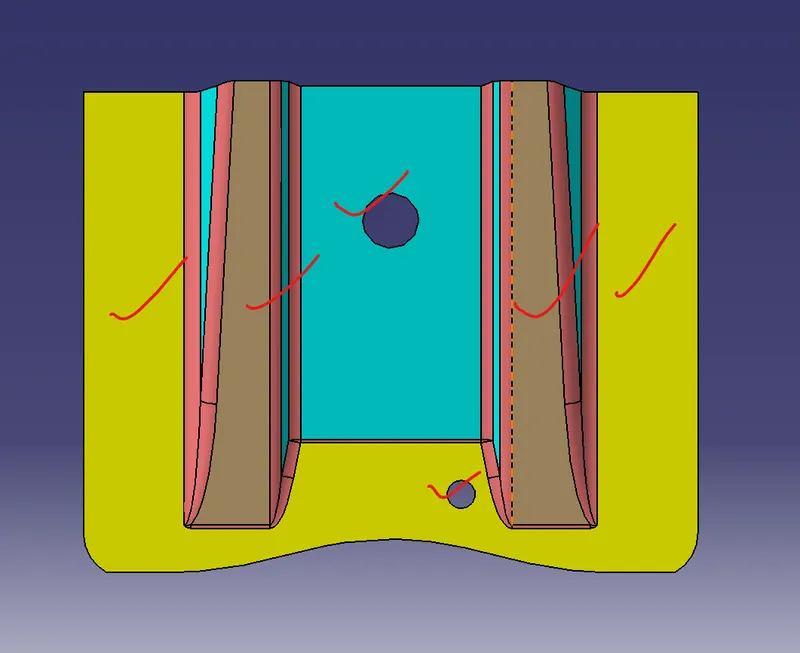
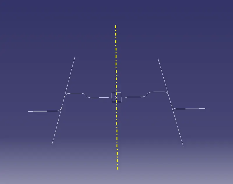
6) Now created point on center of circle over slant surface and by line command with point to direction created dummy axis in Z direction.Then take intersection with surface and created two lines and extended it. further by line command with bisecting option created tooling axis.
B SURFACE
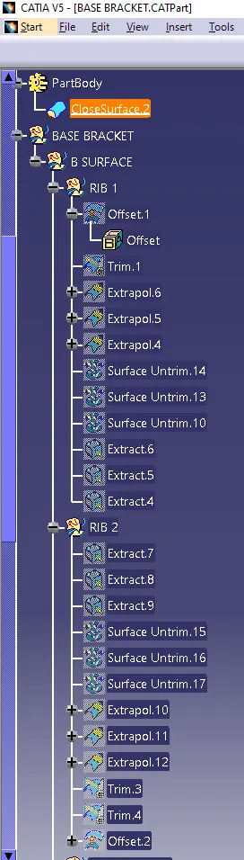
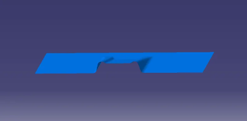
1) Extracted side and upper surface of RIB 1 with extract command , then using untrim and extrpolate command untrimed and extrapollated all extracted surfaces.

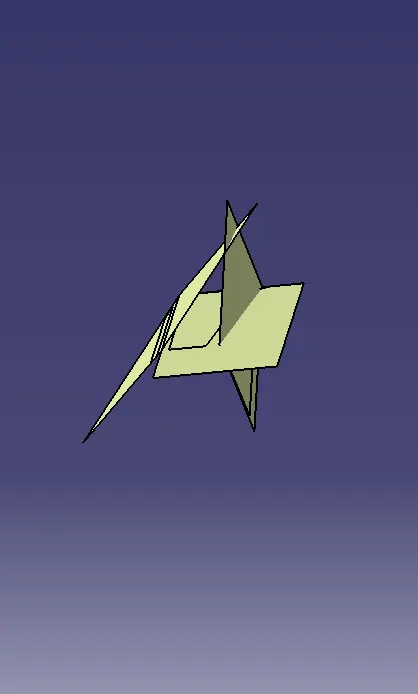
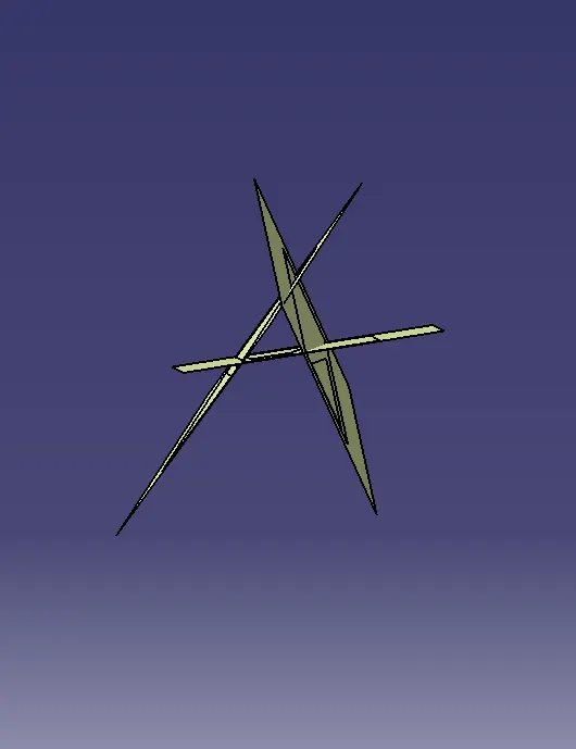
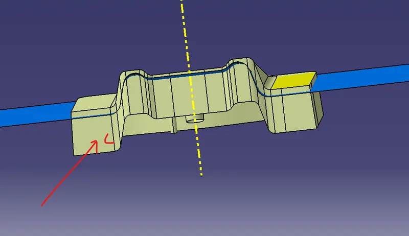
2) Trimed all parts that unwanted to get desired shape and then offseted new surface with 2.5 mm downward side.
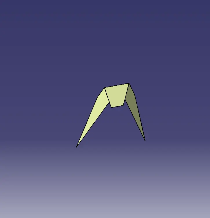
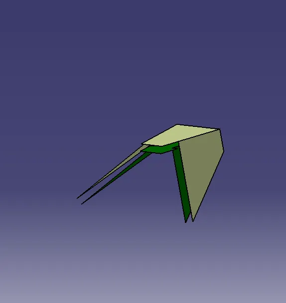
3) Similarly use commands for RIB 2 first extracted three surfaces then untrimed and extrapolated it. then using trim command and got desired shape
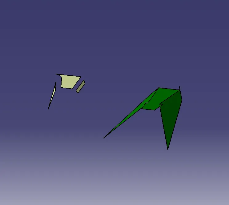
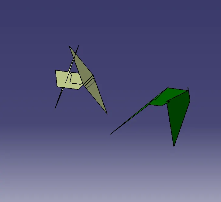
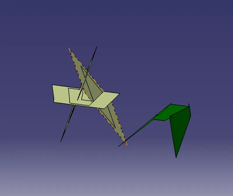
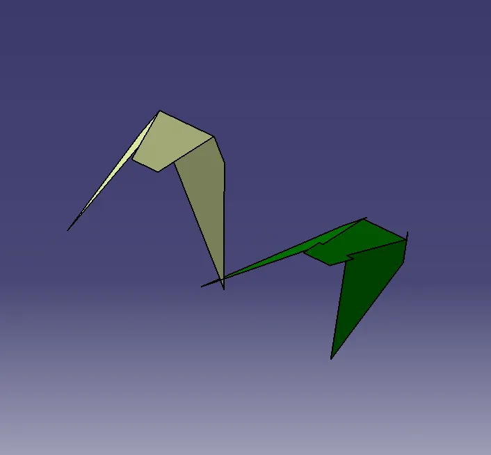
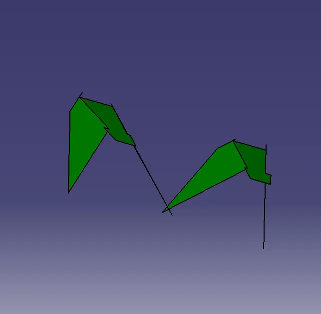
4) Extracted slant surface and offseted it with 2.5 mm downward side also untrimed and extrapolated it.
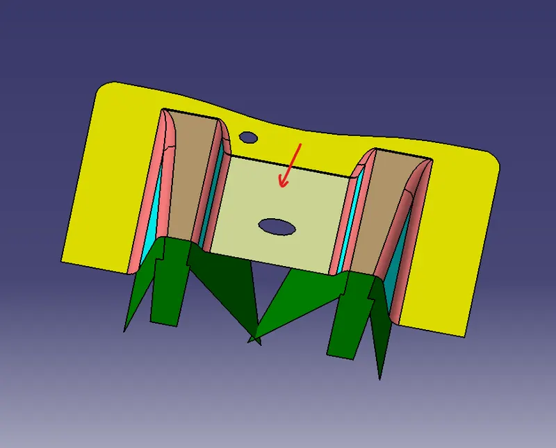
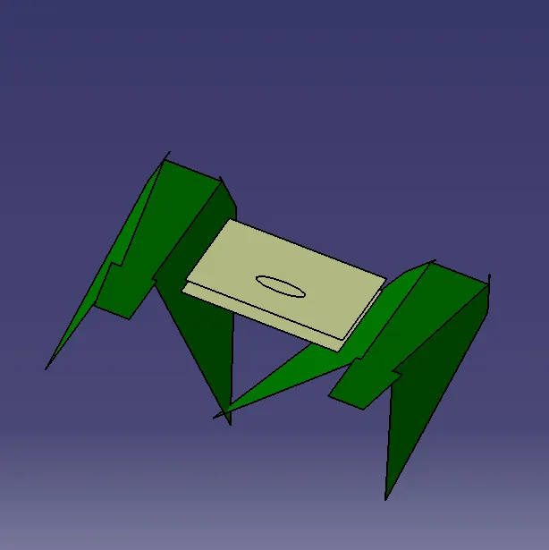
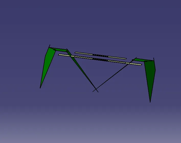
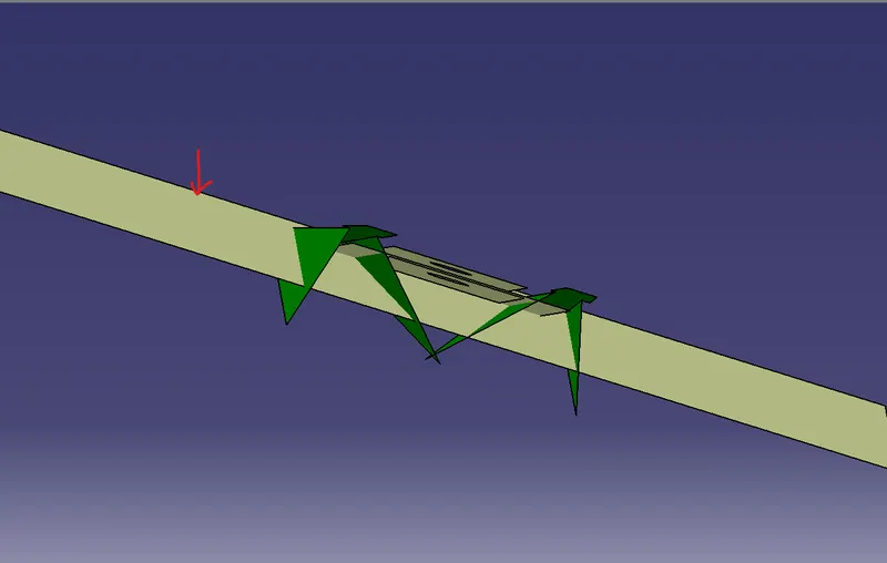
5) Then trimed both sides ribs with extrapolated surface and got required shape.
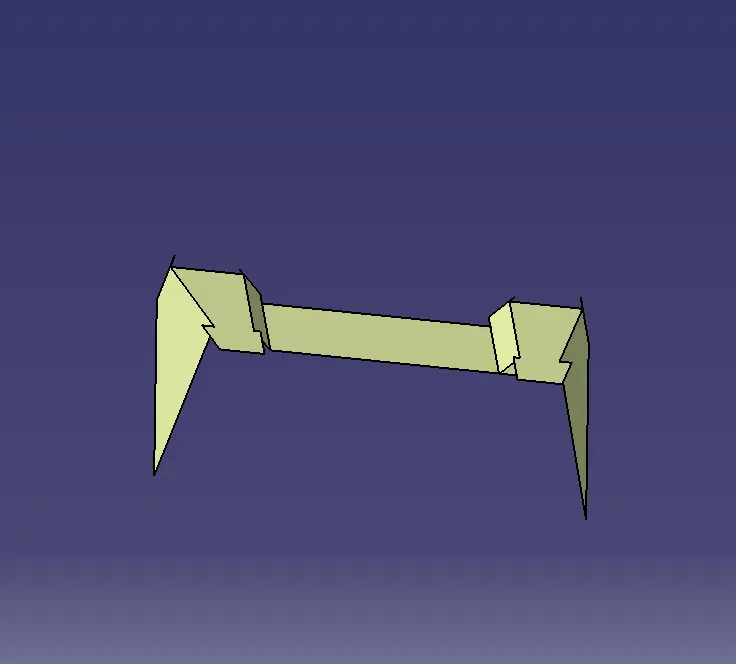
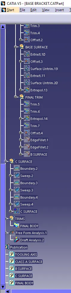
6) Gave final trim to this recently getted shape with extraploated slant surface and after filleted got B surface.
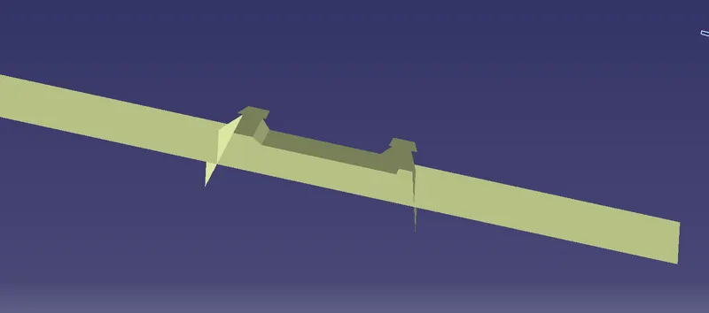
C SURFACE
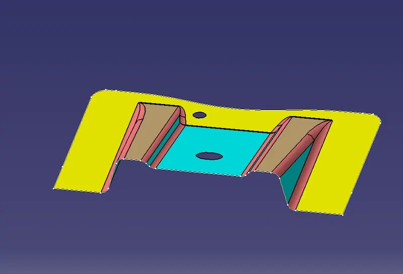
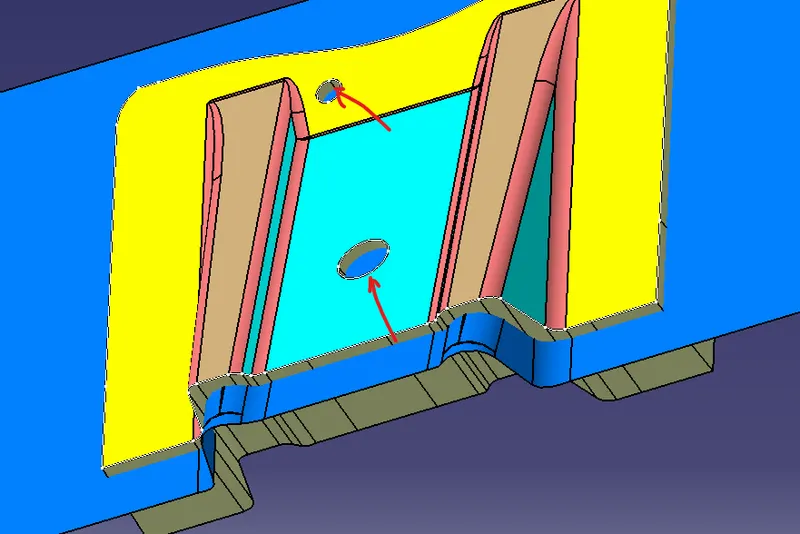
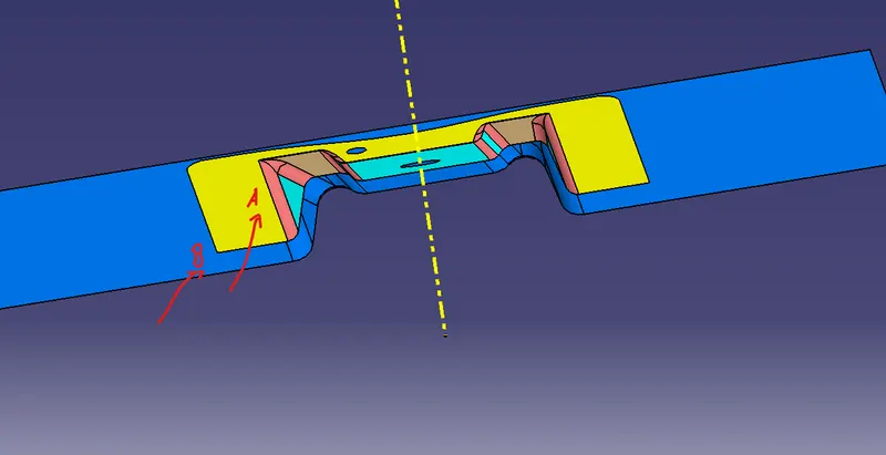
1) For C surface first selected boundry of class A surface then using sweep command sweeped it. then join class A surface with surface getted after sweep. And finally got C surface.
FINAL BODY
1) Trimed C surface with B surface and got final body
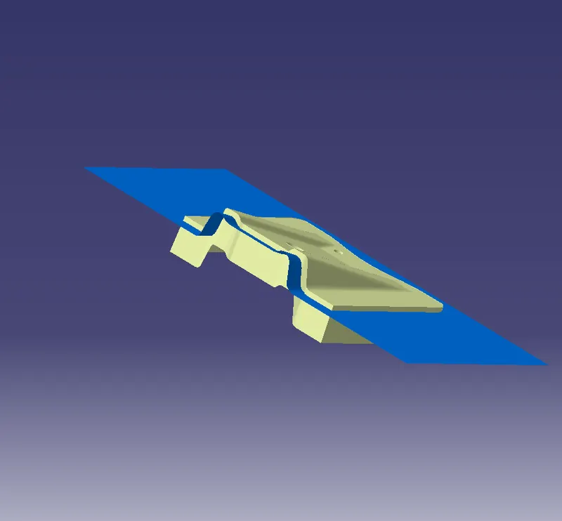
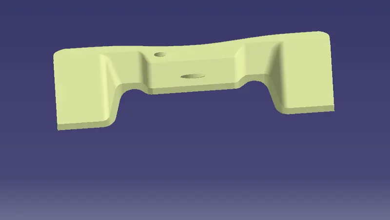
SOLID BODY
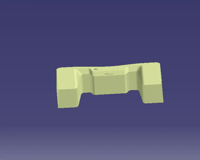
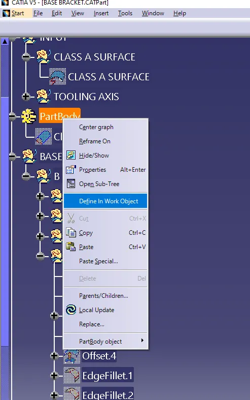
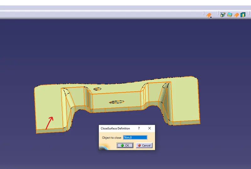
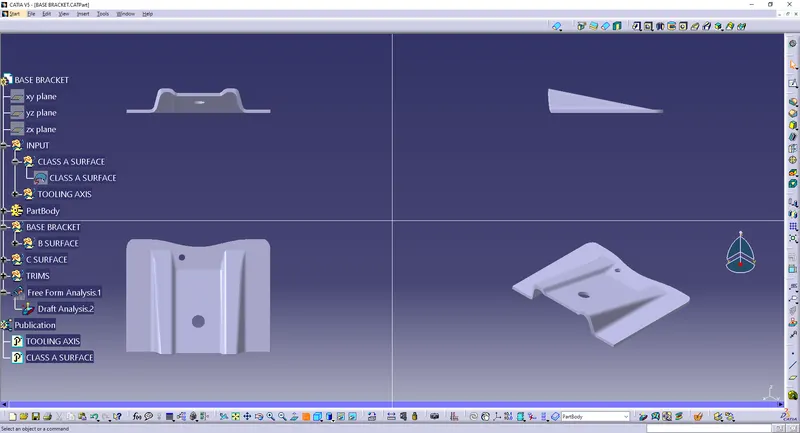
1) First defined partbody then go to part workbench and used close surface command and selected surface and got solid body.
DRAFT ANALYSIS
DRAFT ANALYSIS OF CLASS A SURFACE
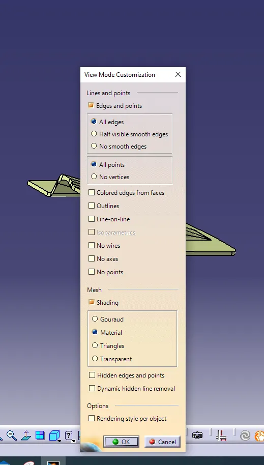
1) First checked whether view was customised view and material is selected then go to draft analysis tool.
2) Then selected compass and draged into alined with tooling axis locked it, clicked on surface and get green surface means drafting was correct and showed differnt draft angle with differnet surfaces.
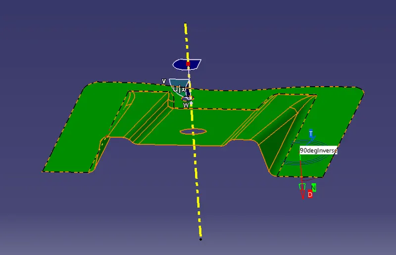
Same Process Doned For B and C Surfaces.
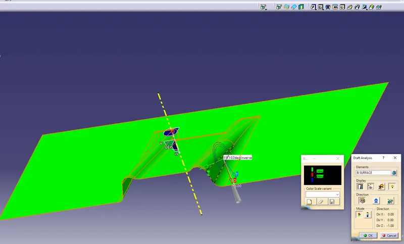
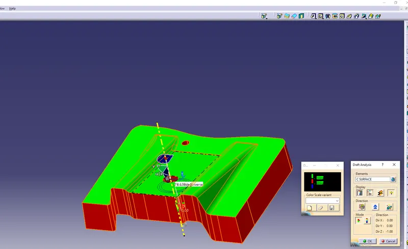
SOLID MODEL WITH DRAFT ANGLE .
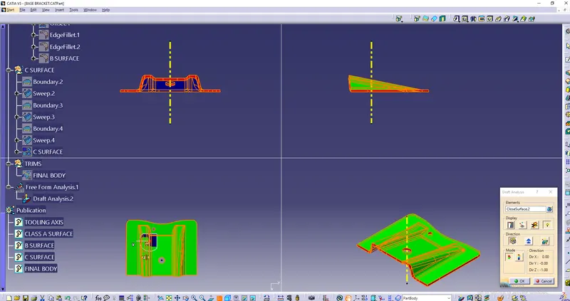
PUBLICATION
1) Selected which wanted to published then go to tools and selected publication command and published it.
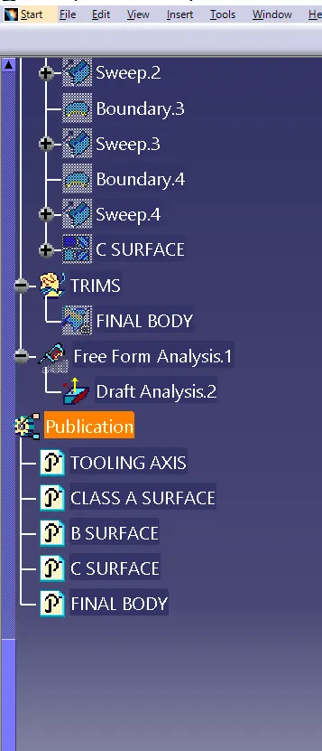
DETAILED TREE STRUCTURE