Project - B PILLAR creation with Master Sections using CATIA V5.
AIM: The objective of this project is to develop a Closed Surface Model of B Pillar using the Class A Surface and make the required attachment features for the fixation of B Pillar with the help of Master Sections by following the proper Design Rules and Procedures followed by the OEMs.
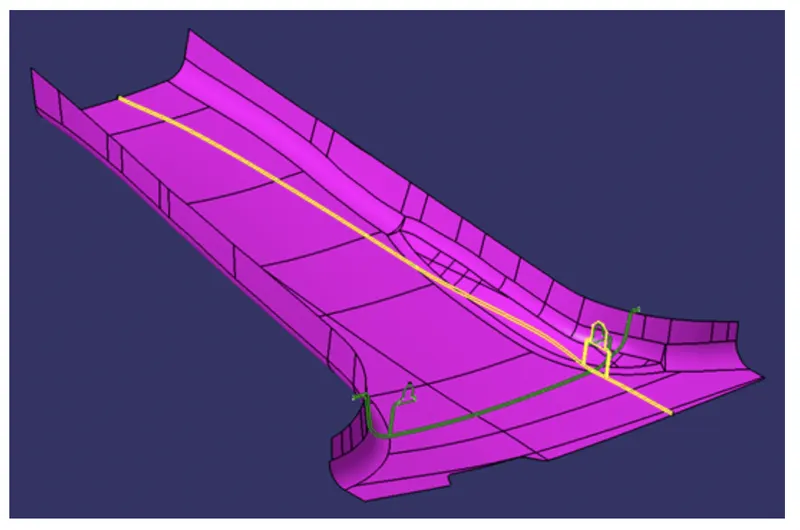
Class A Surface with Master Sections.
OBJECTIVES:
- To ensure proper Tree Structure is followed.
- Creating a Tooling Axis and following Design Rules.
- Creating Class B and Class C Surface using Class A surface as an input.
- Following the Master, Section to create a Flange.
- Following the Master Section for thickness and to create the Closed Volume.
- Following the Master section to create Attachment features.
THEORY:
- B Pillar:
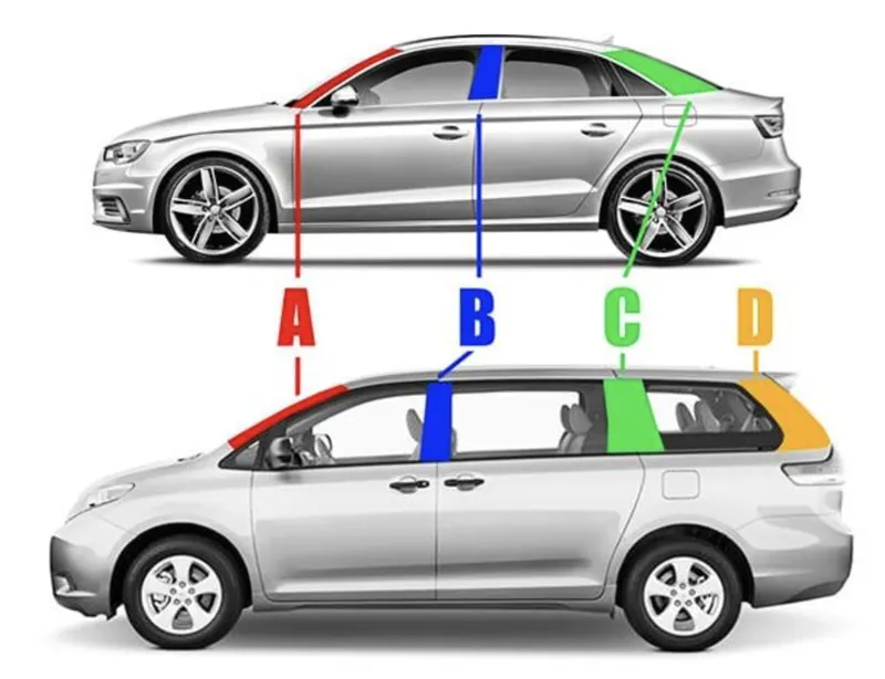
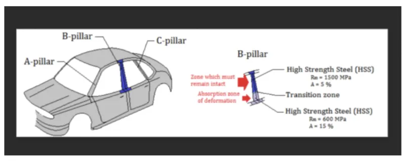
The B-Pillar is the post between the front and back seat doors of a car, connecting the roof to the body. It can also be defined as the vertical roof support structure located between the front and rear doors of a typical vehicle. It corresponds with the A-Pillar located on either side of the windshield at the front of the car and the C pillar which sits on either side of the rear window on a typical sedan car.
- Master Section:
Master Sections are the guides for Design requirements which shape the component after the technical styling of Class A Surfaces. The body frame is mainly composed of floor longitudinal beams, upper side beams, door sill beams, and front cover, the rear beam, A-Pillar, B-Pillar, C-Pillar and other load-bearing beam structures are composed.
Master Sections are parameterized model of the vehicle body that outlines the guidelines for the NPD Team.
In this Report, B Pillar Cover Creation with detailed procedures of Surface Development and Attachment features are covered.
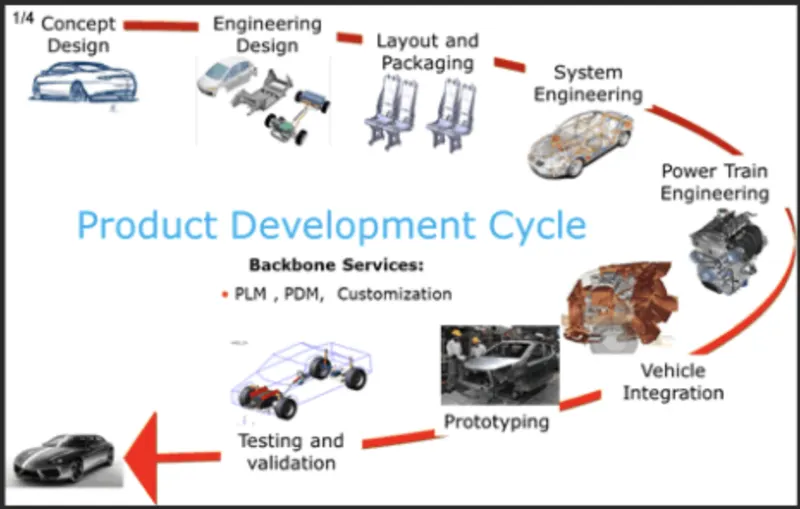
Design Process of Automotives.
- Concept Sketch:
Concept sketches are rough ideas of freehand sketches obtained through a styling team and will be used to prepare the Model. It is usually done through pen and paper and the painting software. This will be used to generate the concept for preparing the model by incorporating various styles and information obtained from the stakeholders.
- Class A Creation:
After finalizing the concept the sketches are usually worked in software such as Autodesk Alias to create Class A Surface.
- Clay Modelling:
The Class A Surface is concurrently worked by clay modellers to brainstorm and benchmark the styling of the product later the Concept is validated by bringing up a rough clay model and then it is passed on to the Design team for the preparation of the New Product Design (NPD) CAD.
- Draft Analysis:
Draft analysis helps to detect if your drafted part is easily removable from the mould (in case of plastic component) or die (in case of sheet metal). All plastic components will have a minimum draft of 0.5 to 3deg. And for automotive sheet metal parts, the draft will be 7deg or more. If a mould wall is perpendicular to the part ejection, there is ample friction or interference between the mould and the part which will not allow one to release from the other. This is why design engineers give a minimum draft to the part.
In CATIA V5 the feature draft analysis dialogue box looks like this:
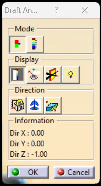
- Mode:
- The mode option lets you choose between quick analysis and full analysis mode.
- In quick mode, there are 3 ranges blue, red and green colours. In the case of the plastic component, we will set the draft angle as 3°.
2. Display:
- The first box is to open and close the colour scale dialogue box.
- The second box is the analysis under the running point when activating the checkbOx and moving the pointer over the surface. This option enables you to perform local analysis. Arrows are displayed under the pointer, identifying the normal to the surface at the pointer location (green arrow), the draft direction (red arrow), and the tangent (blue arrow). As you move the pointer over the surface, the display is dynamically updated. Furthermore, circles are displayed indicating the plane is tangent to the surface at this point. The displayed value indicates the angle between the draft direction and the tangent to the surface at the current point.
- Click the No Highlight Representations button to set the display option of highlight effect sources as 'on/off. When checked 'On" the surfaces are selected but they will not be seen in the specification tree.
- Click the Light Effect button and the colours of the analysed elements react to the light source.
3. Direction:
- The first check box is the locked direction icon which is used to lock the direction of the compass after selecting the specified direction.
- Click on the compass icon to specify the new pulling direction to remove the part.
- Click the Inverse button to automatically reverse the draft direction. When several elements are selected for analysis, the draft direction is inverted for each element when the button is clicked.
- Tooling Direction:
The Tooling Direction is the direction that the mould pulls apart. The mould is built into two separate pieces. You have a Cavity side and you have the Core side. The Core pulls apart from the Cavity and that's the Dyeline or the Tooling Direction. There are different methods to find out the tooling direction. Here we are using bisecting method to find out the tooling direction. We can use any method the ultimate aim is to reduce the cost of manufacturing by reducing the complicity in manufacturing the component.
PROCEDURE:
- Step 1: Checking the Quality of Class A Surface.
- Firstly let's start by checking the quality of the Class A Surface that we have given, to ensure that the surface is fully closed and there are no patches.
- We will use the Boundary Feature to check the Class A Surface.
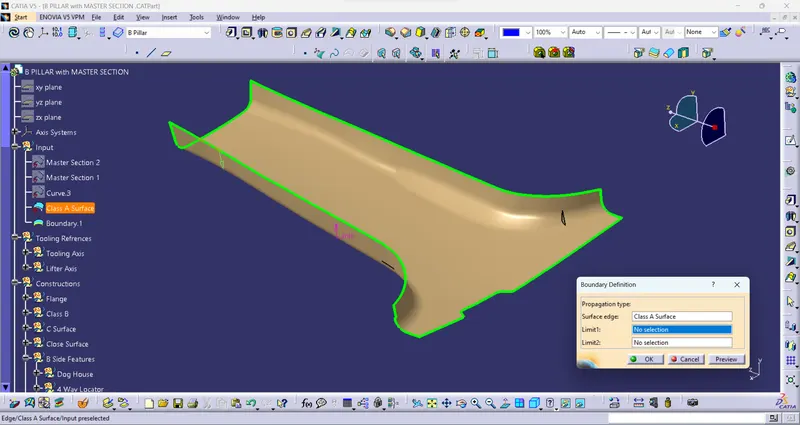
Figure1: Checking the Quality and Boundary of Class A Surface.
- Step 2: Determine Tooling Axis.
- To make the Tooling Axis for B Pillar we will use the Master Section that we have been provided with, we will extract 2 lines out of the Master Section 1 and Two lines out of the Master section 2.
- Then using these lines we will make a point between the lines, we will use alternate lines from each Master Section and create a Bisecting line alone with the point.
- This will lead to having 2 Bisecting lines with us, then using these Bisecting lines we will make one more Bisecting line which will be our Tooling Axis.
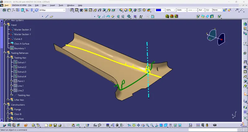
Figure2: Tooling Axis for the B Pillar made using the Master Section.
- Step 3: Draft Analysis of Class A Surfaces:
- Now that we have created the Tooling Axis let's do the Draft Analysis of the Class A Surfaces of B Pillar.
- All the Surface of Class A has A Draft of 3deg, except the little areas on the edges.
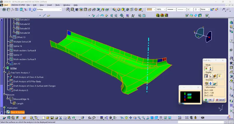
Figure3: Screenshot of Draft Analysis of Class A Surface of B Pillar.
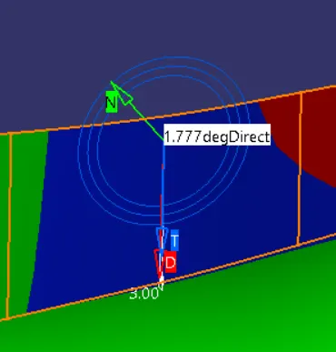
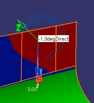
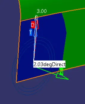
Figure4: Above images show the little areas which are having a draft value between 0-1deg the negative values.
- Step 4: Creating Flanges on Class A Surface:
- Creation of Flange 1 (Left Side):
- As we can see that the Class A Surface doesn't have the Flanges and we need to create and attach them to the Class A Surface.
- We will start by creating a Plane on the Class A Surface and using this plane we will intersect the Class A Surface with the Master Section 2.
- After this let's Extract the required Boundary edges and the Surface faces.
- Let's use the Sweep operation to create the Flanges using the Extracted elements. We have to make sure that the Angle of the Flange while sweeping must be equal to the Master Section 2.
- We will use the Smooth Curve operation to make the Sweep a little more aesthetic looking.
- Now let's Offset this Flange to 2mm as it is the thickness of the component. We have the Left Side Flange for Class A Surface.
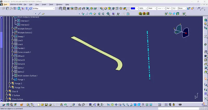
Figure5: Final look of the Left Side Flange of Class A Surface of B Pillar after the above operations.
- Creation of Flange 2 (Right Side):
- To create the right side Flange we will need to do the same process that we did for the left side.
- Following the same steps that we did above, by doing we will get the right side Flange.
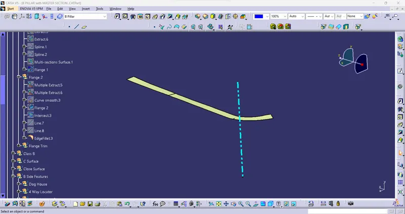
Figure6: Final look of the Right Side Flange of Class A Surface of B Pillar after the above operations.
- Adding the Flange to the Class A Surface:
- Let's Trim the Flange 1 and Flange 2 i.e both side Flanges with the Class A Surface to create the Class A Surface with Flanges.
- After the Trim operation let's give the respective fillet values to the Flanges.
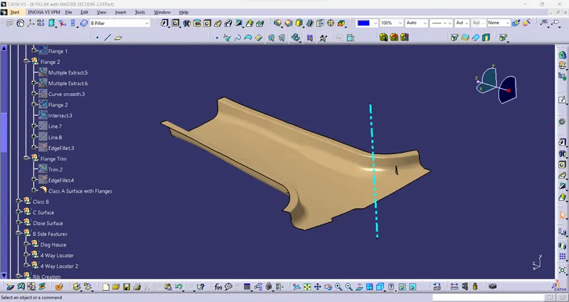
Figure7: Final look of Class A Surface with Flanges after the above operations.
- Step 5: Creating Class A Surface of B Pillar:
- Let's start by offsetting the Class A Surface to a value of 2mm. Then we will offset the Flanges made for the Class A Surface to 2mm.
- We will Extrapolate the offset Class A surface a little so that the trim with the Flanges will happen easily.
- After the Extrapolate we will Trim the 2 Flanges with the Extrapolated Surface to get the Class B surface with the Flanges. We will give the required fillet to this surface also.
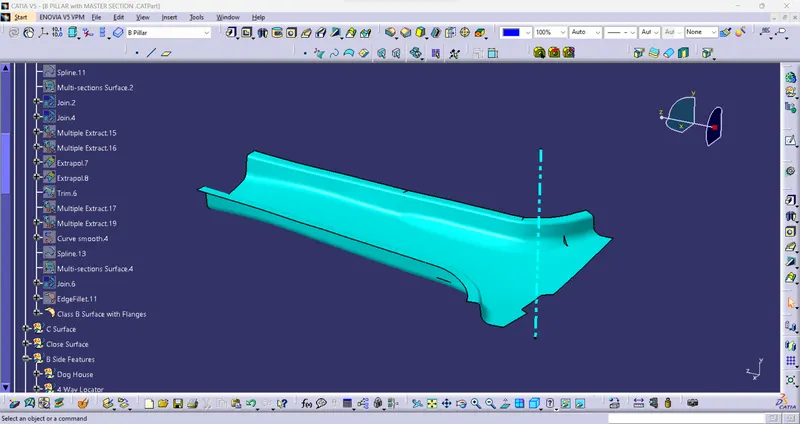
Figure8: Final Class B Surface of B Pillar after the above operations.
- Step 6: Creating Class C Surface of B Pillar:
- For the C Surface, we need to Multiple Extract the Boundaries of the Class A Surface with Flanges.
- Let's perform the Sweep operation on the Extracted Boundaries to create the C Surface that we require.
- After we have all the surfaces we have to create the C Surface let's see if we need to Extrapolate them to do the Trim operation, if yes we will Extrapolate the surfaces to the required amount.
- Now we will Trim the Extrapolated surfaces and create the Class C Surface.
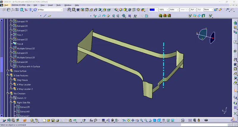
Figure9: Final Class C Surface of B Pillar after the above operations.
- Step 7: Creating the Close Surface of B Pillar:
- Now for the Close Surface, we will Trim the Class C Surface with the Class A Surface to create the Trim of C Surface with A Surface.
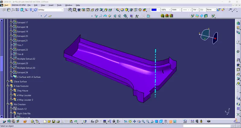
Figure10: Trim of Class C Surface with Class A Surface.
- Now we will use the above Trim and Trim it with the Class B Surface to get the Close Surface of B Pillar.
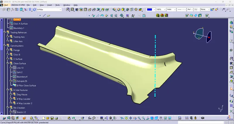
Figure11: Trim of Class C and A Surface with Class B Surface for the Close Surface.
- Step 8: Creating the Close Surface Body of B Pillar:
- Now for the Close Surface Body of the B Pillar, we need need to go to the Part Design workbench and insert a body and then use the Close Surface Tool on the Close Surface of the Door Applique to create the Body out of it.
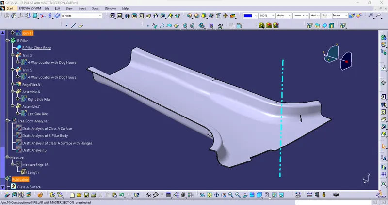
Figure12: Final Close Surface Body of B Pillar after the above operations.
- Step 9: Creation of B Side Features for B Pillar:
- Dog House:
1. Sketch:
- With the help of the Master Section let's create and Plane and a Point so that we can use them to create sketches.
- With the help of the reference lines of the Master Section, we will create the below sketches which will be used to create the Dog House.
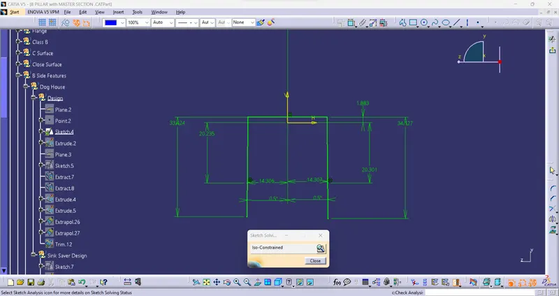
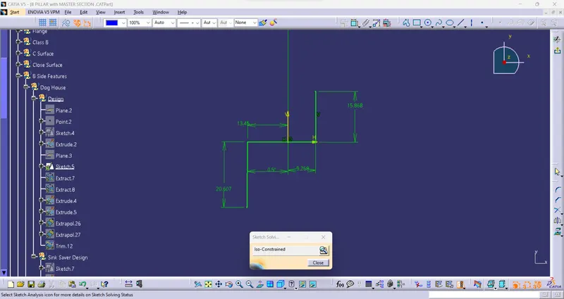
Figure13: Sketches required to make the Dog House.
2. Surface:
- We will Extract, Extrude and Extrapolate the sketches so that we can Trim them all together to get the final surface as below.
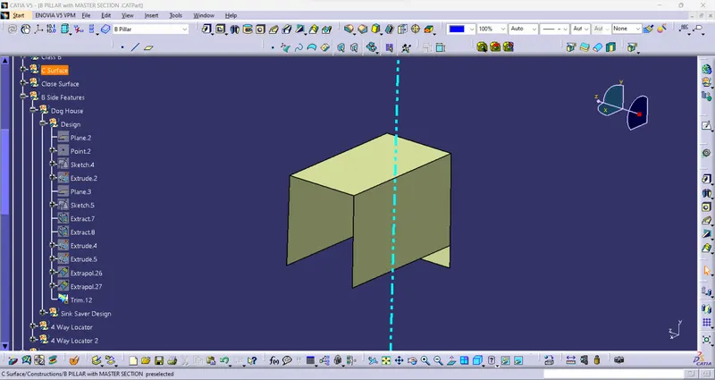
Figure14: Surface required for the creation of Dog House.
3. Body:
- Firstly we will create a body and use the Thick Surface feature on the Dog House Surface to make it into a Thick Body.
- Then we use the Split Body from the Part design to get the exact length that we need.
- Then we will give a 0.5deg Draft to the inside and outside of the Body that we have created.
- Now we will again Split the bottom part with the Class A Surface so that it fits perfectly with the Close Body of B Pillar.
- After this, we will give Fillet to the Outside 1mm and Inside 2mm.
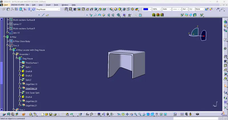
Figure15: Final look of the Dog House after the above operations.
Now we need to make the Sink Saver Design for this Dog House.
1. Sketch:
- Let's start by sketching the Sink Saver Design.
- We will take the reference from the Master Section to create the sketch.
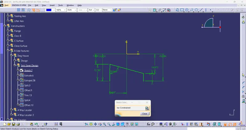
Figure16: Sketches required to make the Sink Saver for the Dog House.
2. Surface:
- Now that we have created the sketch we require we will Extrude it, and Extrapolate it to the required length.
- Then we will take the last Split surface in the creation of the Dog House and Offset it at 0.753mm.
- Now we will Trim this Offsetted surface with the Extrude of the Sketch.
- Then again Split it to the required length and offset it at a distance of 1.9mm.
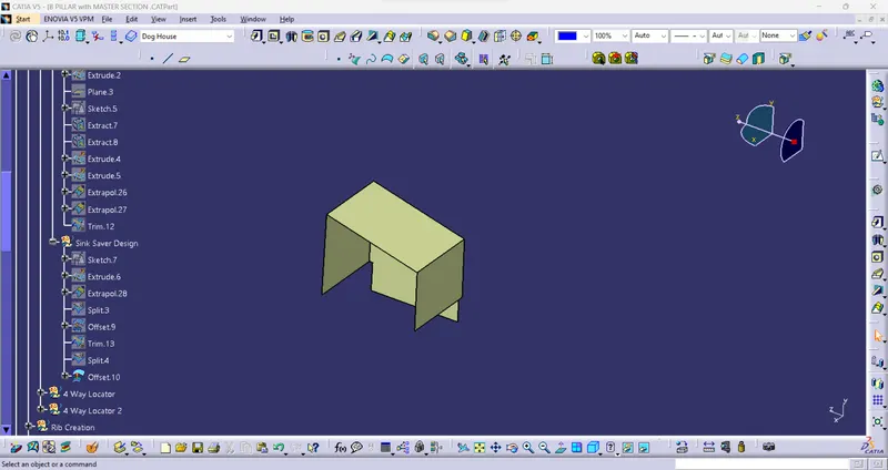
Figure17: Final Look of the Sink Saver Surface after the above operations.
3. Body:
- Now we will Split the above Offset surface with the Dog House Body to create the Sink Saver Cutout.
- Then we will give a 0.5deg Draft to the inside of the Sink Saver Cutout that we have created.
- After this, we will give Fillet to the inside edges as 0.9mm and an overall fillet of 0.3mm.
- Now we will Union Trim this fully finished Dog House with the Close Body of B Pillar.
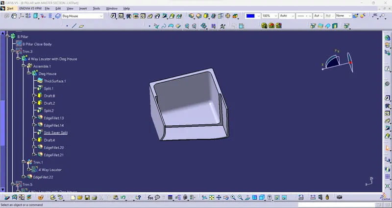
Figure18: Final look of the Sink Saver Cutout for the Dog House after the above operations.
- Step 10: Creating Locators for B Pillar:
- Sketches:
- First, we will start by making a plane on top of the Dog House.
- Now we will make a Sketch as mentioned below, the below Sketch is for 4-Way Locators.
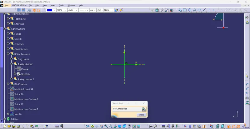
Figure19: Sketch of the 4-Way Locator of B Pillar.
- Body:
- Firstly we will create a body and Pad the 4-Way Locator Sketch to a required height of 20mm, and make it thick with a Thickness value of 1.5mm with the Neutral Fiber option turned on.
- Then we will give 0.5deg Draft to the Padded 4-Way Locator.
- On the top 4 edges, we will give the Chamfer of 5.4mm and 1mm Fillet to the Chamfered edge.
- We also need to give an overall Fillet of 0.3mm all over the 4-Way Locator.
- Now we will Union Trim this fully finished 4-Way Locator with the Dog House that we have created.
- Add an overall fillet of 0.3mm to the base of the trim operation.
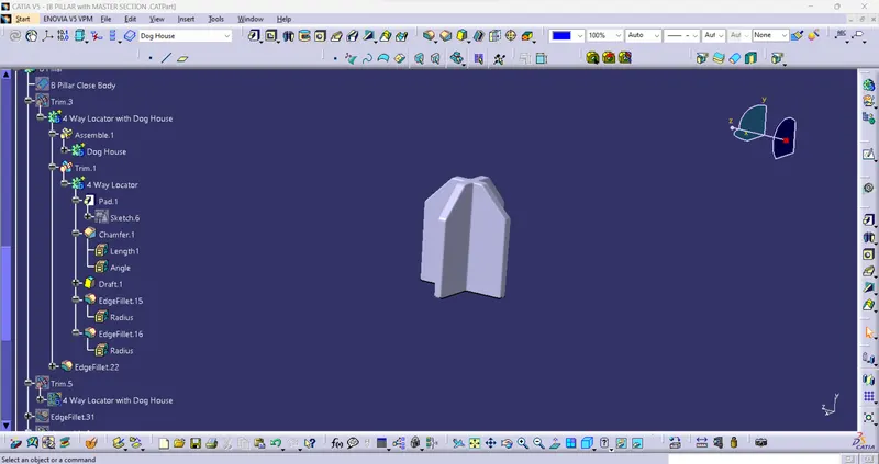 w
w
Figure20: Final Body of the 4-Way Locator after the above operations.
- Step 11: Creating Left Side 4-Way Locator with Dog House:
- Sketch:
- Let's create a point using Master Section 2 as the reference. On the created point let's create a point.
- Now that the body is moved using the Symmetry we have to extend its length. To do this let's make two-point on the inner edge of the Dog House.
- Using these two-line we will create a line and Extrude this line.
- Body:
- Let's start by copying the Body of the 4-Way Locator with Dog House and paste it using the paste special with link option.
- Now let's Symmetry this body to the left side of the B Pillar using the Plane we have created using the Master Section 2.
- Now that the body is moved to the required position let's split the Extruded surface with the body.
- Now that we have a split face we can Pad it to 30mm, and also give the 0.3mm fillet on the faces.
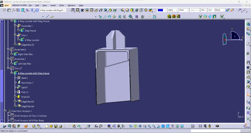
Figure21: Final Body of Left Side 4-Way Locator with Dog House.
- Step 12: Creating Locators for B Pillar:
- Rib Creation:
1. Sketch:
- With the reference to the Close Body of B Pillar, we will create the Sketch lines for the creation of the Ribs.
- Bellow Shown is the sketch of the Ribs for both sides of the part.
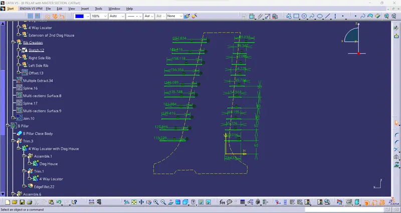
Figure22: Sketches required to make the Ribs.
2. Surface:
- Now we will extract each line that we have created in the sketch separately.
- After the Lines are Extracted we will Extrude them to a certain height but not more than the Flanges.
- For the Split operation on, we will need the Class B Surface and the offset of the Class B Surface at 10mm.
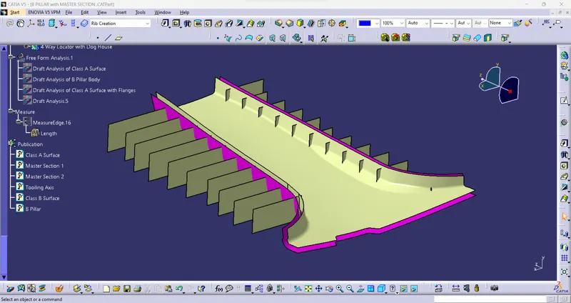
Figure23: All the required Surfaces for the creation of the Ribs.
3. Body:
- Now to create the Solid-body for the Ribs let's use the Thick Surface option to thicken the Extruded surface to a 0.8mm.
- Now that we have a Solid body we need to give the shape of the Rib to do that we will first do the Split operation with the Offset surface of the Class B Surface.
- To get the final look of the Rib we need to again Split it but this time with the actual Class B Surface. Now we have the Rib that we need for the B Pillar.
- We will give a Draft of 0.5deg to the faces of the ribs and a Fillet of 0.3mm too.
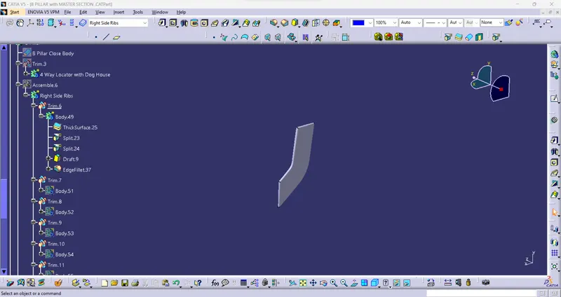
Figure24: Final look of the Rib after the above operations.
- We will do the same operation that we have done above to create the rest of the Ribs.
- Then we will Union Trim these Ribs to the main Close Body of the B Pillar.
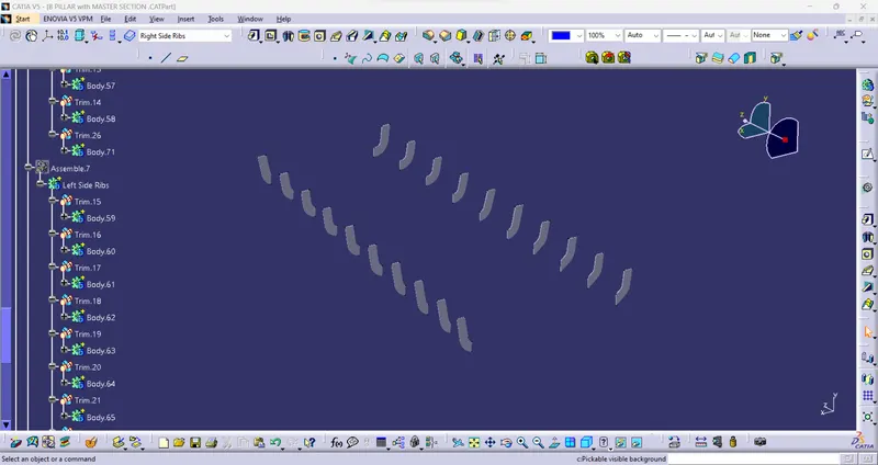
Figure25: Final look of all the Ribs after the above operations.
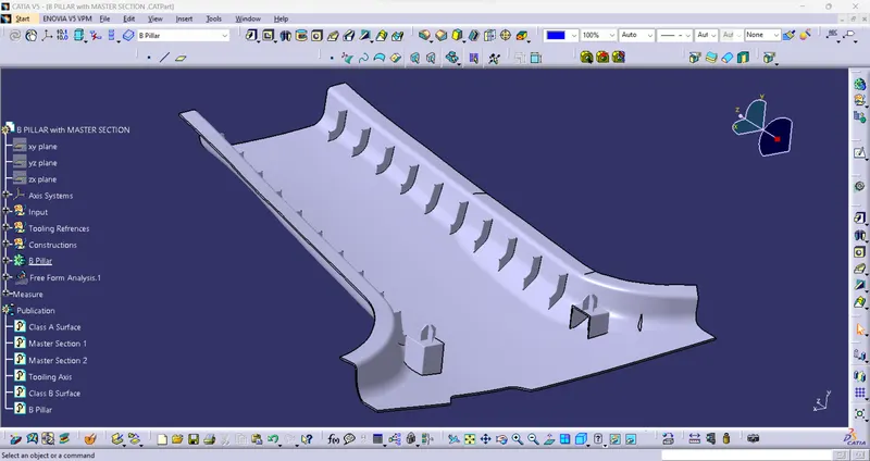
Figure26: Final look of the B Pillar with all the B Side Attachments.
- Step 13: Draft Analysis of B Pillar:
- Class A Surface of Close Body:
- The Draft Analysis of the Class A Side of the B Pillar Close Body.
- All the Surfaces have the Draft of 3deg except the areas highlighted below.
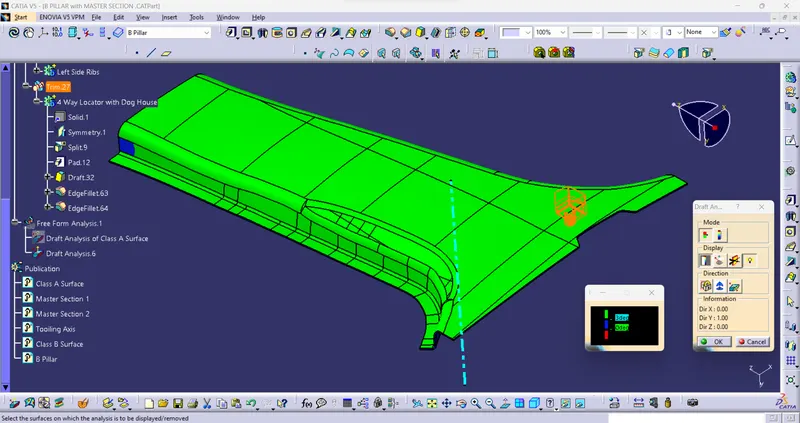
Figure27: Draft Analysis of the Class A side Surface of the B Pillar Close Body.
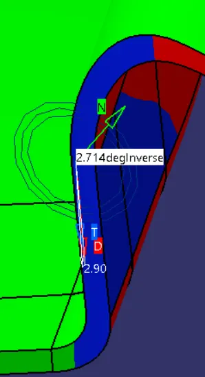
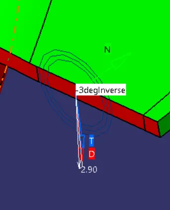
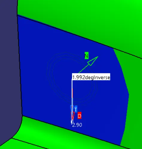
Figure28: Area on the Class A Surface where the Draft is not 3deg.
- Class B Surface of Close Body:
- The Draft Analysis of the Class A Side of the B Pillar Close Body.
- All the Surfaces have the Draft of 3deg except the areas highlighted below.
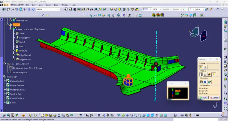
Figure29: Draft Analysis of the Class B side Surface of the B Pillar Close Body.
- In the below image we can see the draft analysis on the Locator and Ribs are at 0.5deg.
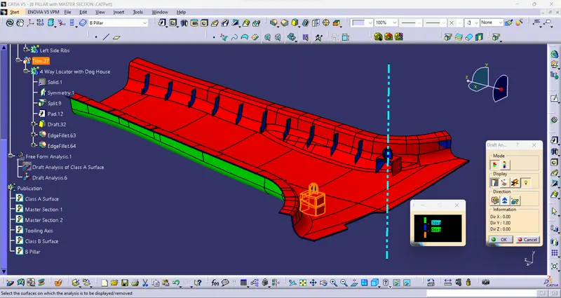
Figure30: Draft Analysis of the Class B side Surface of the B Pillar Close Body showing the Draft of Ribs and the Locators.
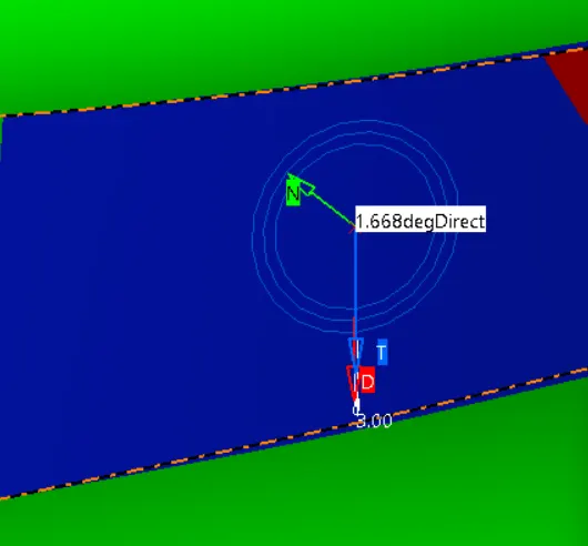
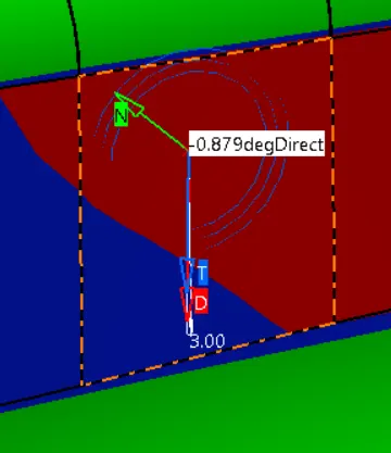
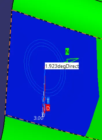
Figure31: Area on the Class B Surface where the Draft is not 3deg.
- B Side Features:
- For the calculation of Draft Analysis on the B Side Feature Attachments like the Dog House, we will make a new Tooling Axis which is called the Lifter Tooling Axis.
- All the areas of the B Side Features of Dog House have been designed maintaining a draft of 0.5deg to the Lifter Tooling Axis.
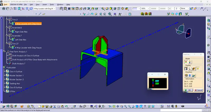
Figure32: Draft Analysis of the Dog House.
- All the areas of the B Side Features of Ribs have been designed maintaining a draft of 0.5deg to the Lifter Tooling Axis.
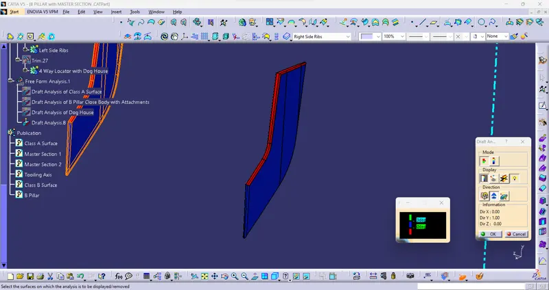
Figure33: Draft Analysis of the Ribs.
- Terms asked to Mention:
- Tree Structure:
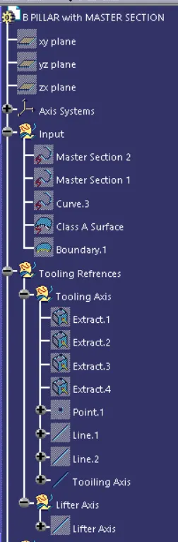
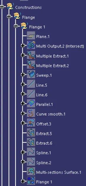
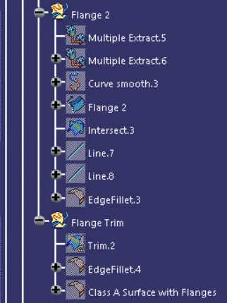
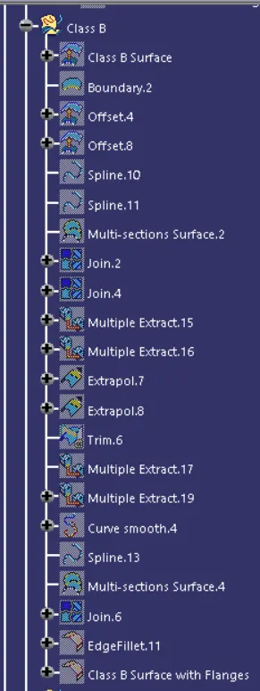
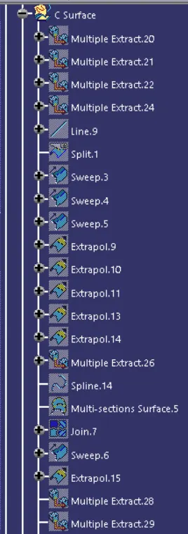
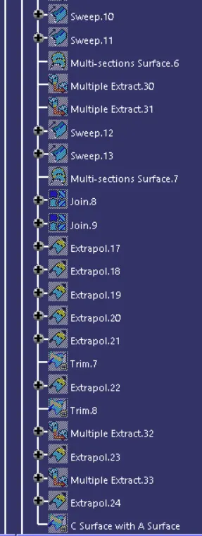
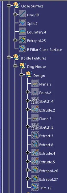
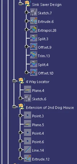
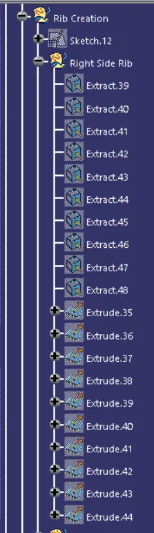
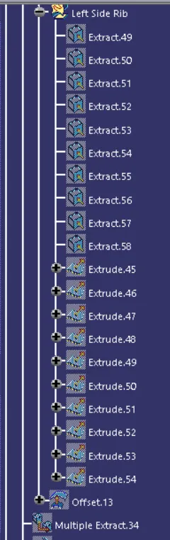
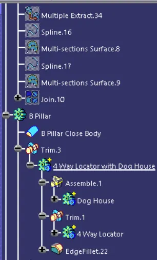
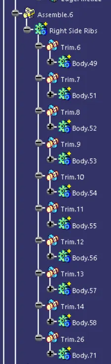
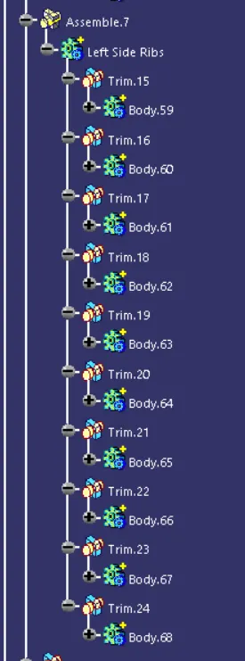
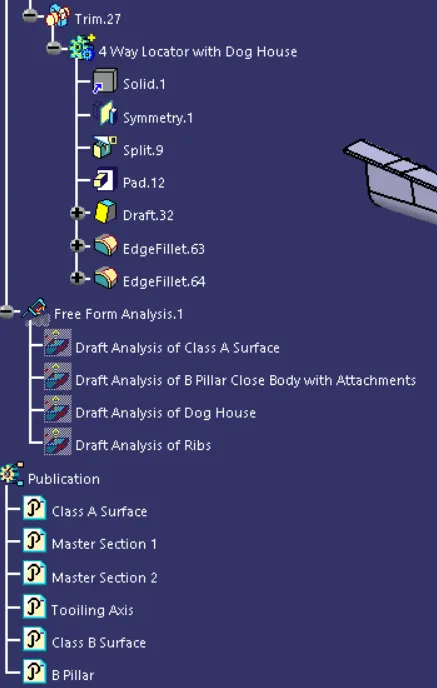
Figure34: Tree Structure of B Pillar.
- Model in various orientations (Isometric, Front, Side, and Top View):
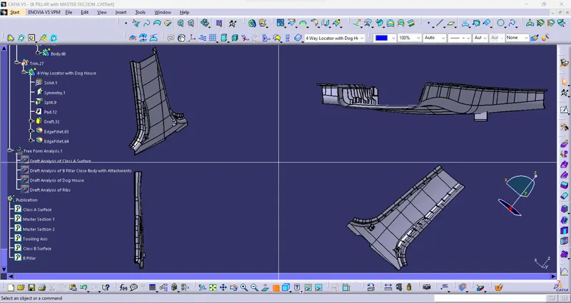
Figure35: Model in Various Views.
RESULT:
- Creation of Tooling Axis for B Pillar.
Figure36: Result of creating Tooling Axis for B Pillar.
- The Draft Analysis of the Class A Surfaces.
Figure37: Result of Draft Analysis of Class A Surface of B Pillar.
- Creating Flanges for Class A Surface.
Figure38: Result of Class B Surface of Door Applique.
- Creating Class B Surface of B Pillar.
Figure39: Result of Class B Surface of B Pillar.
- Creating Class C Surface of B Pillar.
Figure40: Result of Class C Surface of B Pillar.
- Creating the Close Surface of B Pillar.
Figure41: Result of Close Surface of B Pillar.
- Creating the Close Surface Body.
Figure42: Result of Close Surface Body of B Pillar.
- Creating Dog House with Sink Saver for B Pillar.
Figure43: Result of the Dog House with Sink Saver.
- Creating a 4-Way Locator for the Dog House.
Figure44: Result of 4-Way Locator for the Dog House.
- Attaching the 4-Way Locator with the Dog House.
Figure45: Result of 4-Way Locator attachment with the Dog House.
- Creating Ribs for the B Pillar.
Figure46: Result of Ribs for B Pillar.
- Attaching all the B Side Features to the B Pillar Body.
Figure47: Result of all the attachment of the B Side Features to the B Pillar Body.
- Draft Analysis of Class A Surface of Close Body.
Figure48: Result of Draft Analysis of Class A Surface of Close Body.
- Draft Analysis of Class B Surface of Close Body.
Figure49: Result of Draft Analysis of Class B Surface of Close Body.
- Draft Analysis of Dog House with Sink Saver for B Pillar.
Figure50: Result of Draft Analysis of Dog House with Sink Saver.
- Draft Analysis of Ribs for B Pillar.
Figure51: Result of Draft Analysis of Ribs.
CONCLUSION:
To Create B Pillar out of a Class A Surface and add the Features such as the Dog House, Locator and Ribs have been completed by using Industrial principles and Design Rules and performing the Draft analysis on the given Class-A Surface and Final Complete Model of B Pillar with all the attachments.