Week 9 - Project - Master Section Development
Aim :- Master sections Development on a B-pillar surface. create class-B&C surfaces with reference, create features using the guidlines of the master sections. perform draft analysis for the surfaces and features.
Given :-
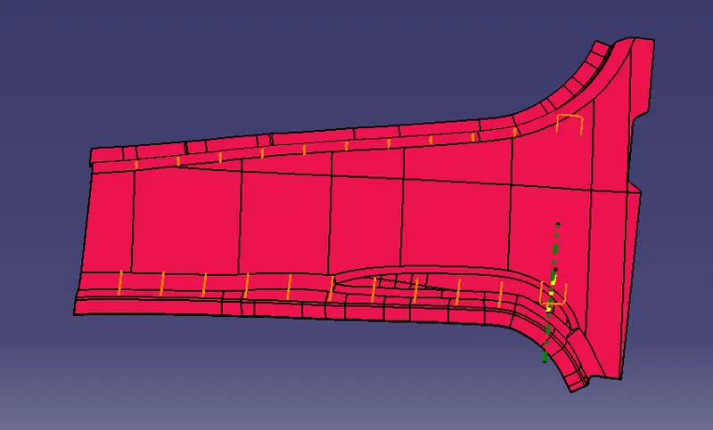
Class-A
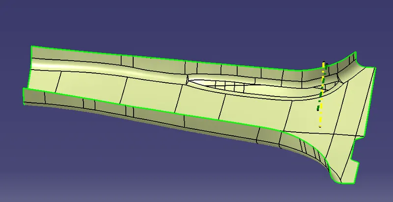
Master sections-
Procedure :-
- The given surface is a class-A , check for the irregularities or gaps in the surfaces. use boundry option to check for the gaps.
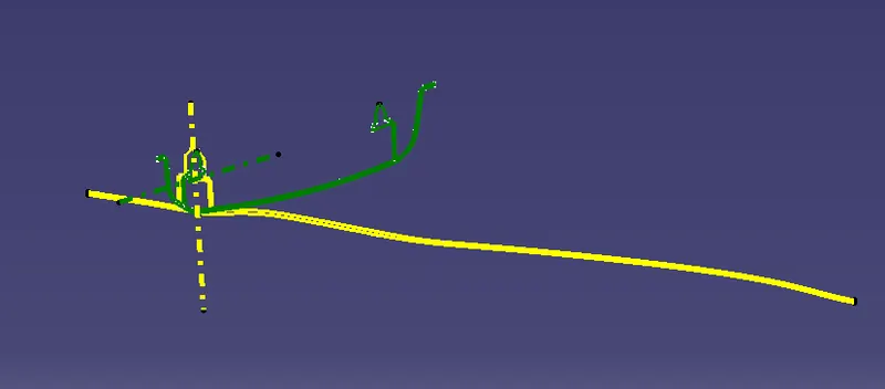
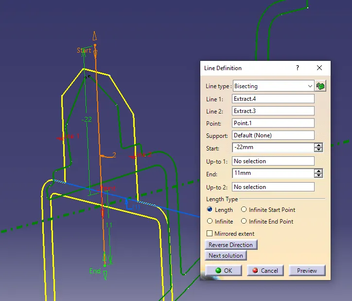
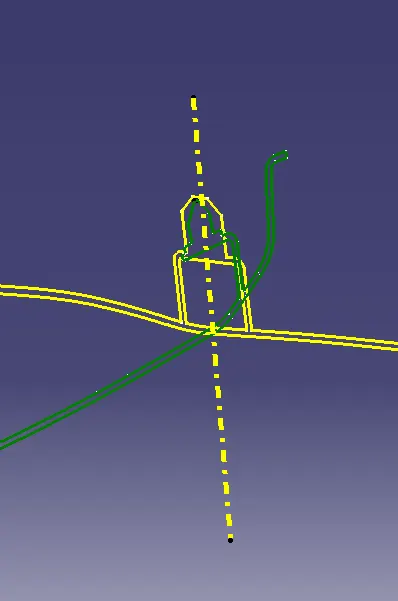
- To create a tooling axis.insert a geometrical set for the tooling axis creation ., use the master section lines, extract the feature lines and by bisecting method create reference lines for the tooling axis. bisect them to get the final line and rename it as tooling axis.
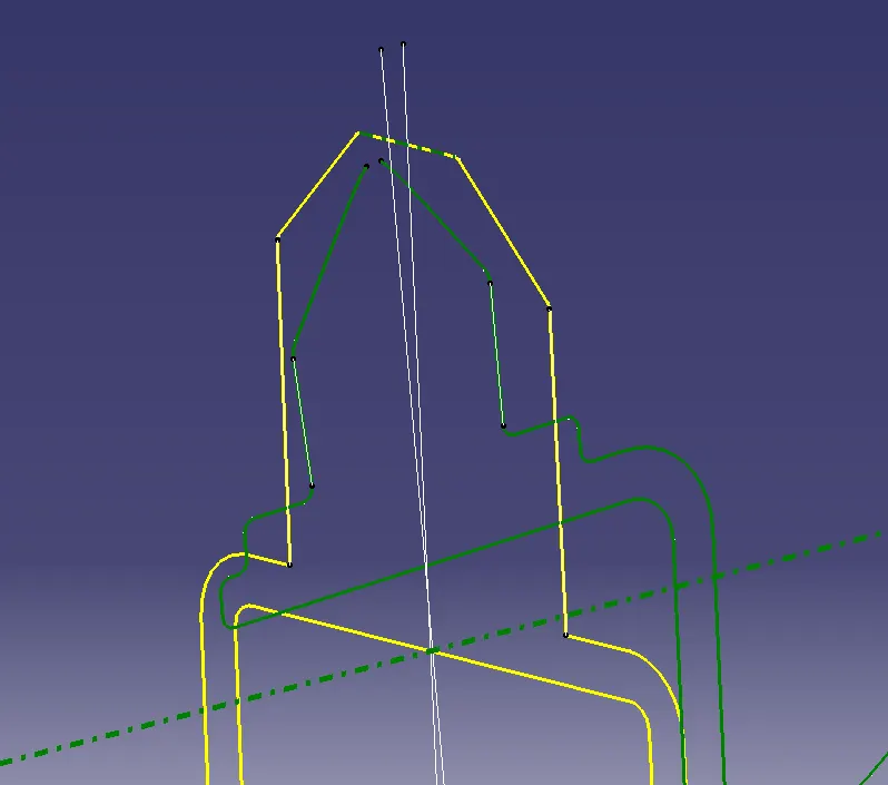
- Now with the reference of the given calss -A surface class-B surface is created . insert a geometrical set and rename it accordingly. extract the boundries of the surface using tangent continuity.
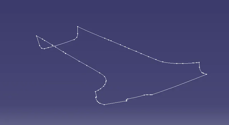
- Off-set the surface to 2mm(thickness of the pillar). and there is a improper surface or gap present on the surface. this can be cleared by multiple extracting the boundries of the gap and using curve smooth fine the curves extracted.

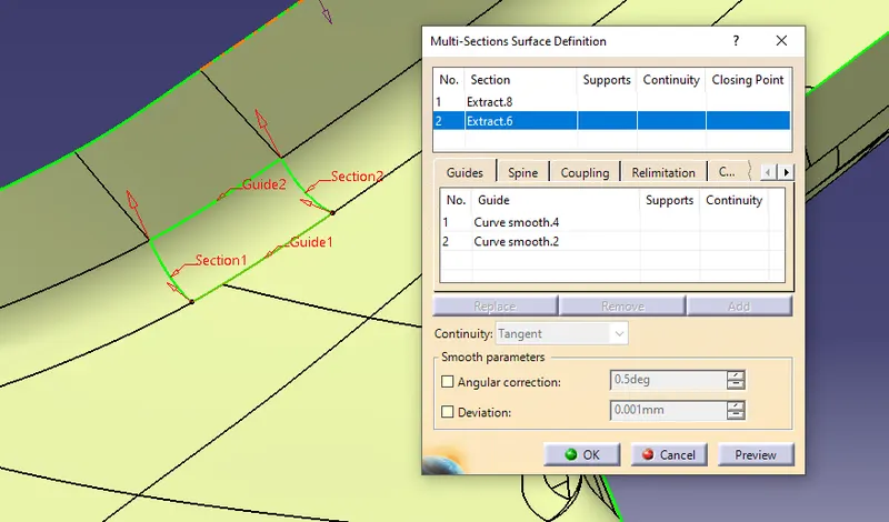
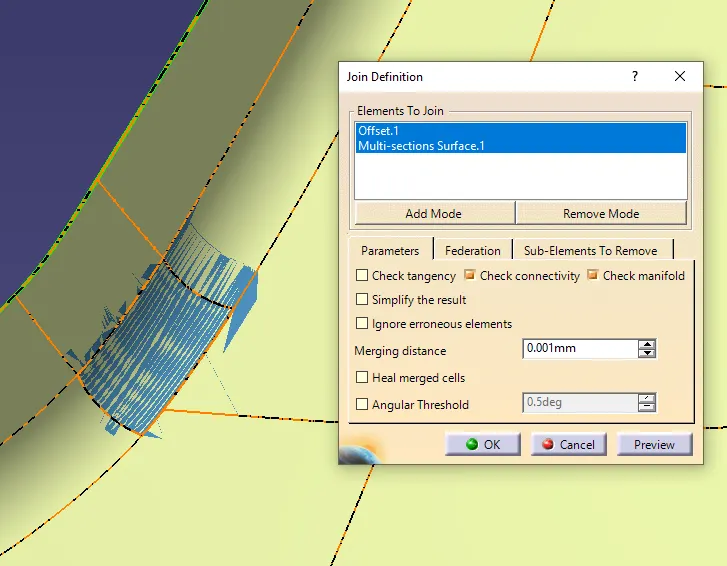
- Now using the multi-section surface define , fill the gap with the surface. select the guiding curves and the direction on both sides should be similar.
- Join the newly created surface with the class-B using join surfaces option. hence a class-B surface is created.
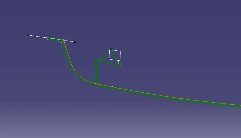
- Now flanges are created. insert a geometrical set and rename it as flange creation, add another set under it and rename it as flange-1.create a plane through the master section point and intersect it in xy-plane with the surface.
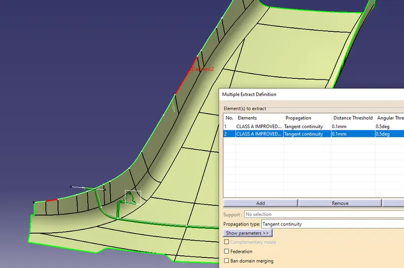
- Unhide the class-A and using multiple extract option extract the boundries and corresponding surfaces through the boundry.use tangent continuity for the boundries and no-propogation for the surface extraction.
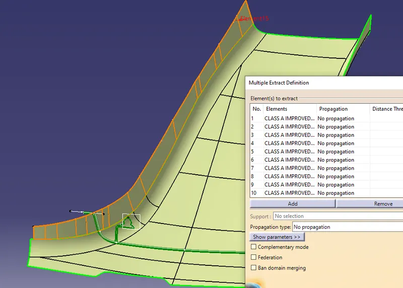
- Now using sweep option (with reference surface), guide curve as the extracted boundry, reference surface as the extracted surfaces using no-propogation. angle as 77 degrees with reference to the intersection line. select the outer direction for sweep.
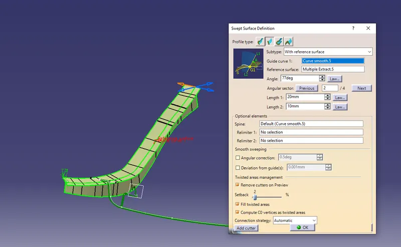
- Now off-set the sweeped surface to 1.5mm towards class-B surface. since the surface is having discontinuity. there is a missing patch of surface.
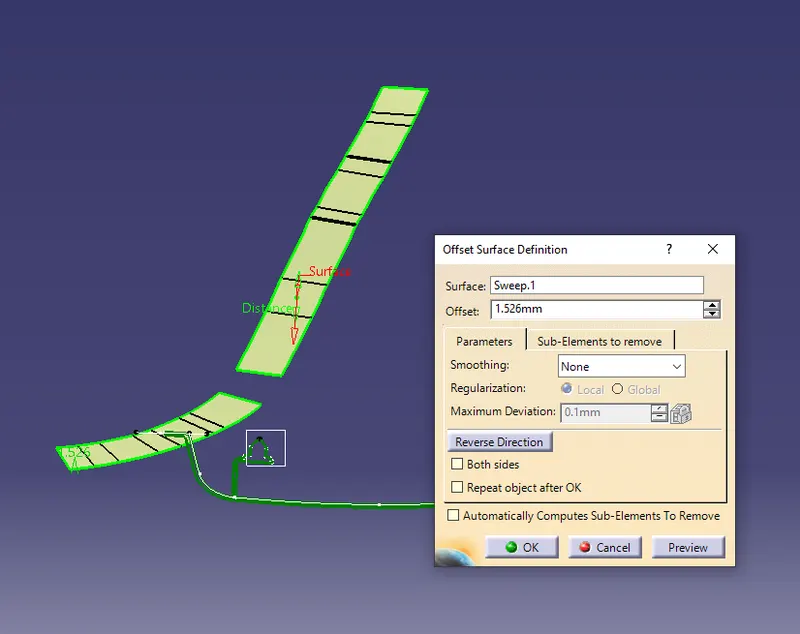
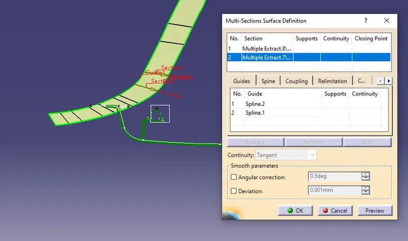
- Inorder to clear the gap.. using multi-extract option extract the boundries and surfaces of the corresponding surfaces around the gap. using multisection surfaces. create a spline over the gap which acts a guide curve.
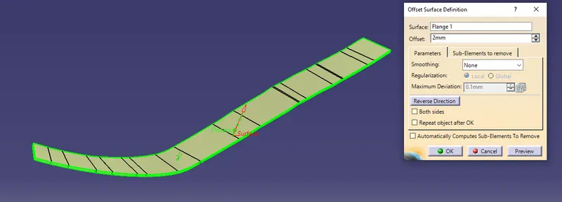
- Now add the newly created patch surface to the flange.and offset the whole flange 2mm towards the class-A surface.
- Similarly. insert another geometrical set for the flange-2 ie,.. on the other side of the pillar. follow the same procedure to create the falnge and trim both the flanges with the class-A surface.
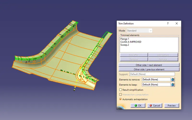
- Add edge-fillets with 2.5mm radius to th edges of the flanges portion.
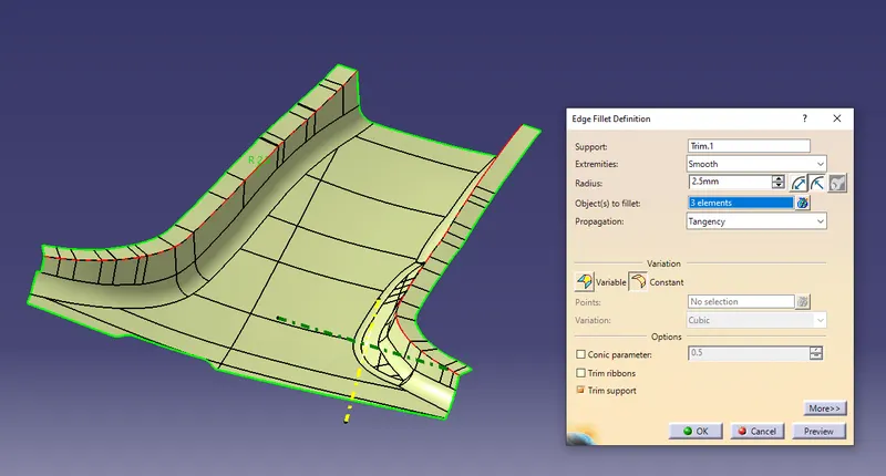
- After adding the fillets to the flanges on class-A. off-set the flange surfaces to the class-B and trim with it. add edge fillets to the class-B surface also. use extrapolate to intersect the class-A and B surfaces with the flange surfaces to trim them perfectly.
class-A with flange-
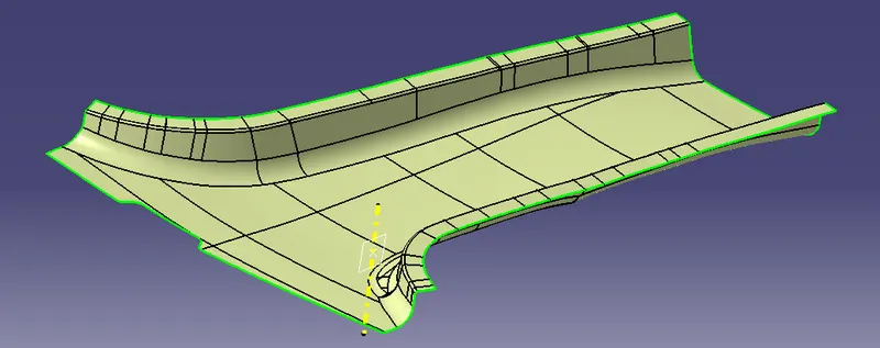
class-B with flange-
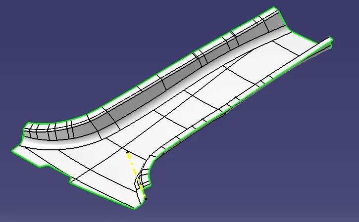
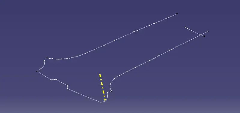
- Class-C is created with reference from the given clas-A flange. extract the boundries of the surface using multiple extract, make sure the straight curves are extracted first.
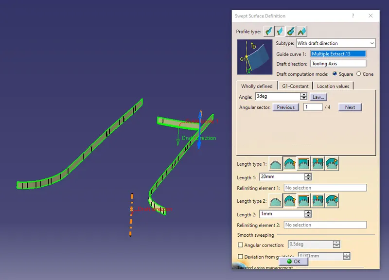
- Using sweep option- with draft direction as tooling axis and 3 degree draft angle sweep the selected boundries towards inside of the component. sweep length is maintained enough so that it can be trimmed properly with the other surface.
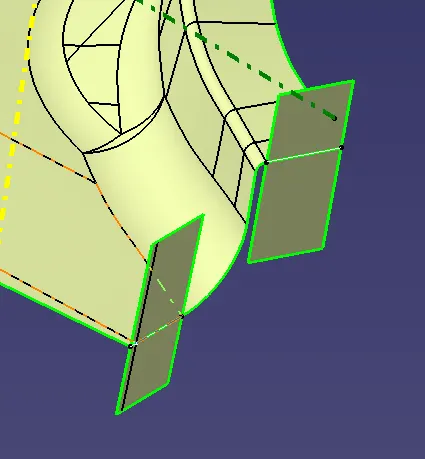
- Select the other portions of the boundries and extract them separately. use multi section surface option to get the complicated curved surface in betweeen the two sweeped surfaces. make sure the direction of the sweep and the guide curve is selected properly.
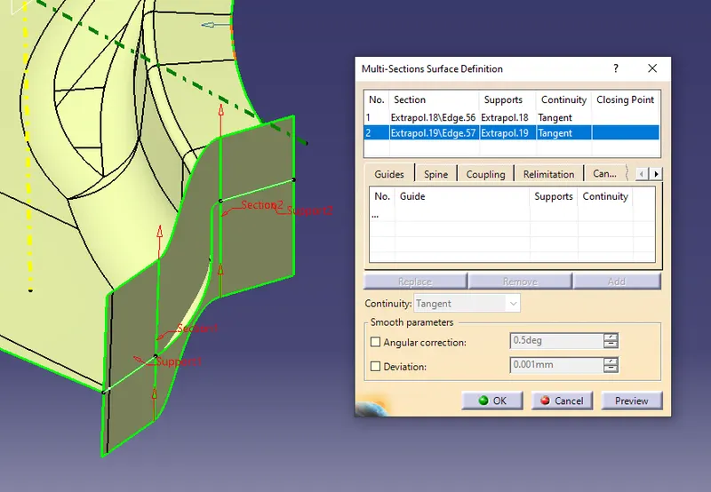
- Perform the similar operation to make the surfaces in the boundries and the other half. extrapolate them to intersect eachother and trim them accordingly / join the surfaces
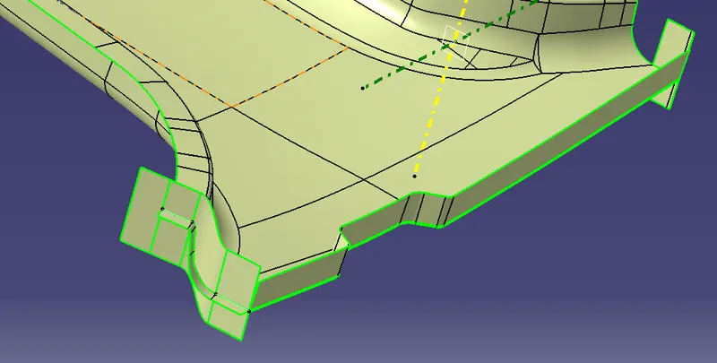
- Now extrapolate the boundries of the class-A properly and trim them with the class-C surface. class-C with class-A is created.
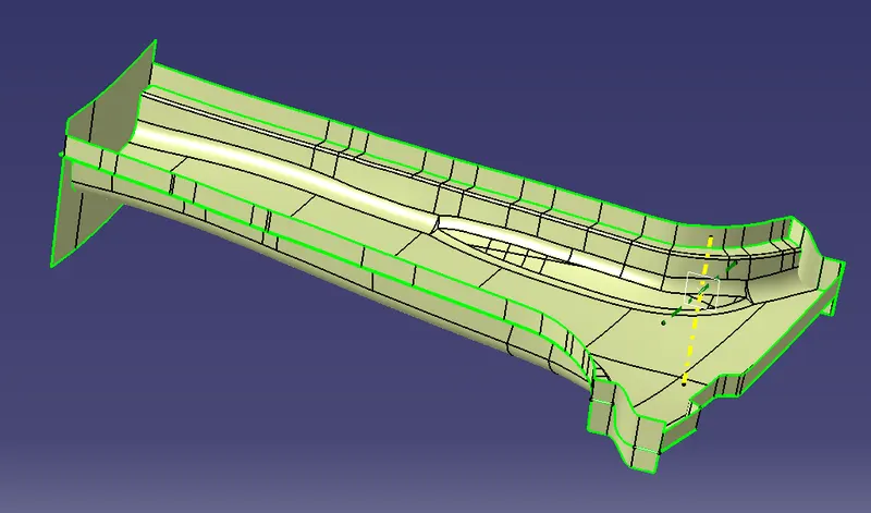
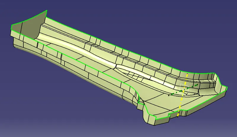
- Trim the class-A,B&C together to get the final trim closed surface. click on boundry option to make sure the created surface is a closed body.
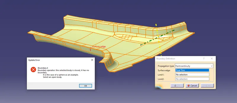
- Insert a part body and name it as B-pillar . Goto part design and using closed surfaces. create a solid body out of the closed surfaces B-pillar created.
- Now features are created on the B-side , insert a geometrical set and name it as B side features , insert another set under it and rename it as Dog house design.
- Extract the lines for the dog house feature creation unhide the planes in perpendicular direction. insert a positioned sketch for the dog housew creation, create two sketches in both the directions. maintain the points equidistant from the centre axis and are iso- constrained.
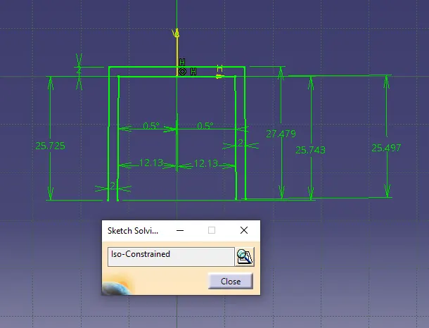
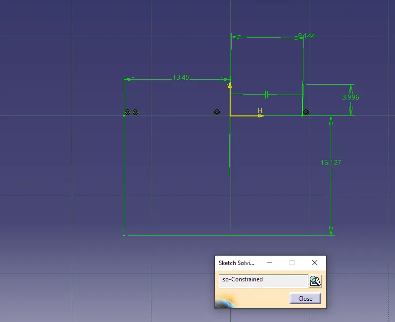
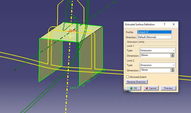
- Using extrude option create the closing surfaces for the sketches created for the dog house design. trim them accordingly
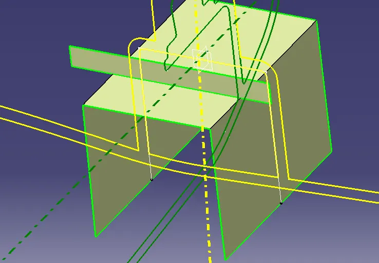
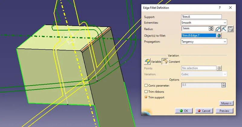
- Add a 1mm edge fillet to the specific edge of the dog house.
- Sink marks cause improper surface finish hence these are avoided by certain design rules. generally due to improper cooling the sink marks occur which are not desirable.
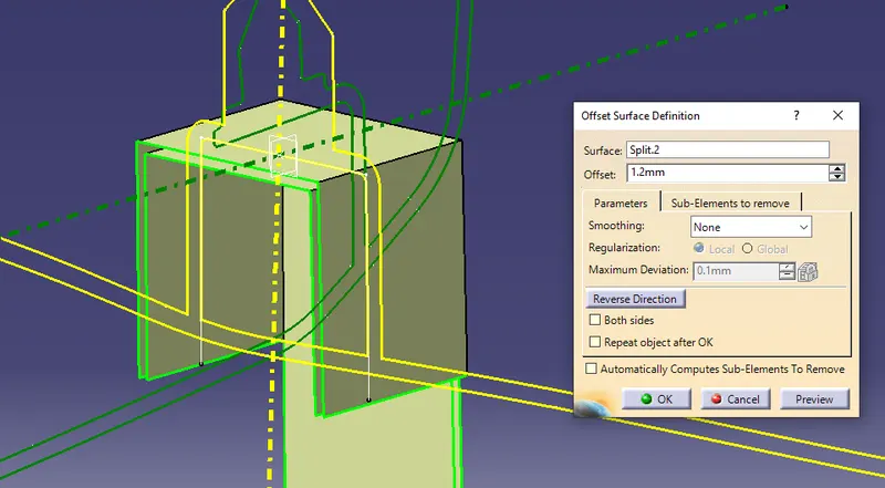
- Insert a geometrical set and rename for the sink marks removal procedure. split the dog house and off-set it to 1.2mm towards outside of the surfaces.
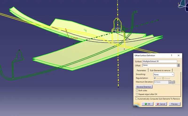
- Now extract the surfaces from the Class-B with flange with no propogation. and off-set to 3mm in upward direction.
- Now the off0set surface is trimmed with the dog house surface keeping the required surfaces. and split the unwanted surface.
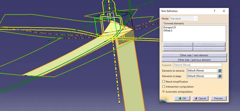
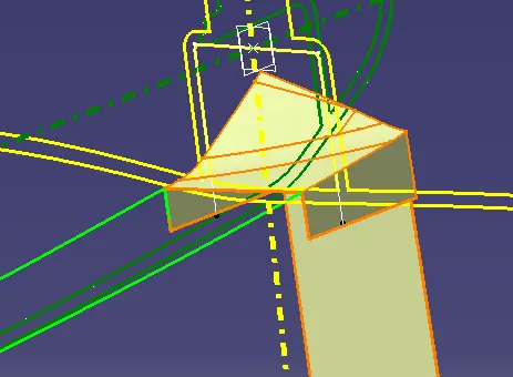
- Now extrapolate the surface of the extracted flange surface from class-b surface. and intersect them to get the curved line on the surface.
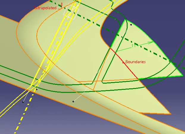
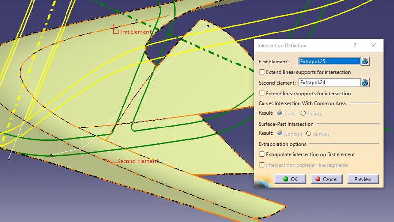
- Create a positioned sketch through the point and the intersecting line created. make sure the sketch is equidistant from the axis and iso-constrained.
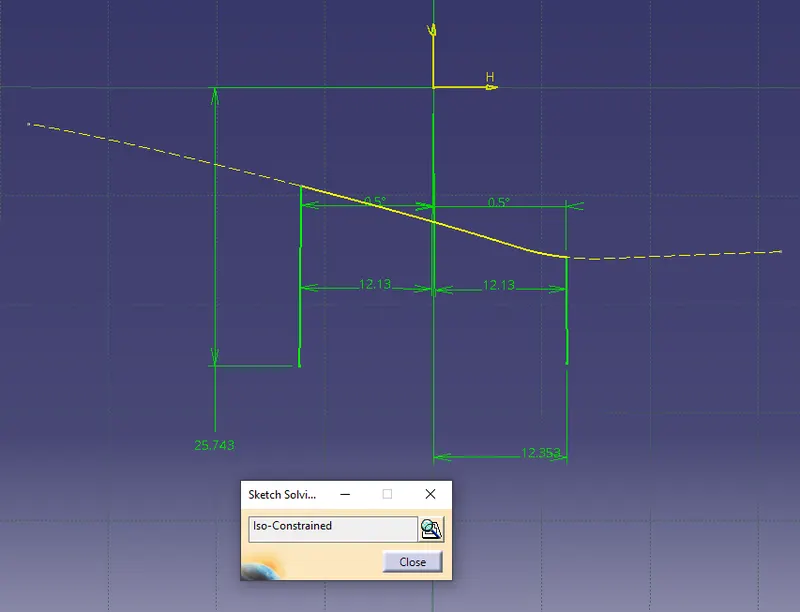
- Exit the sketch and extrude the sketch in both th elimits. trim the extruded surface with the dog house surface.and off-set it to 1.2mm upwards.
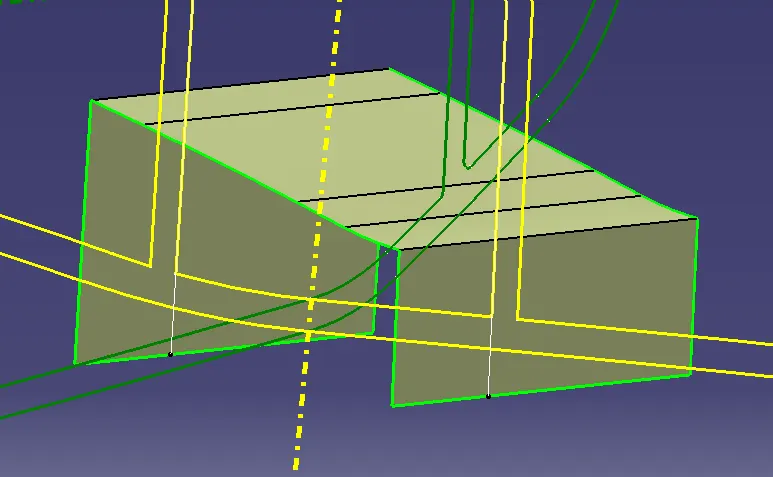
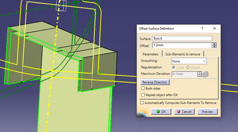
- Create solid body out of the closed surfaces , insert a part body separately for every solid body created. use Boolean operations to add them to the main part body later.
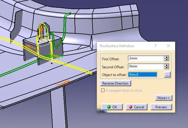
- insert a geometrical set and rename it as 4 way locator. create a positioned sketch through the plane in xz -direction and master section as reference.make sure it is equidistant and iso-constrained.
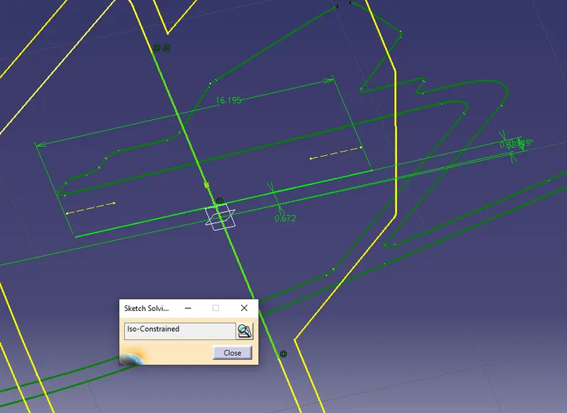
- Insert a part body and pad the sketch to1.5mm thickness with neutral fibre and extend it enough.
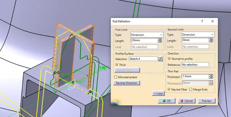
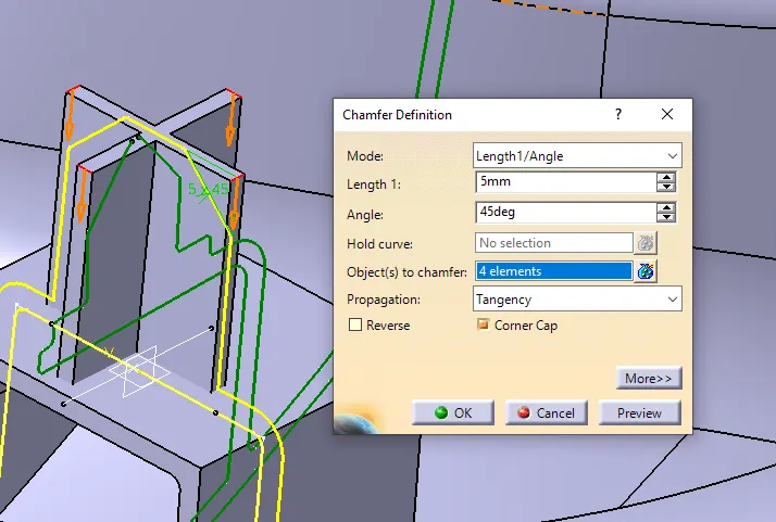
- Add chamfer to the edges of the 4 way locator with 45 degree and 4 mm length.
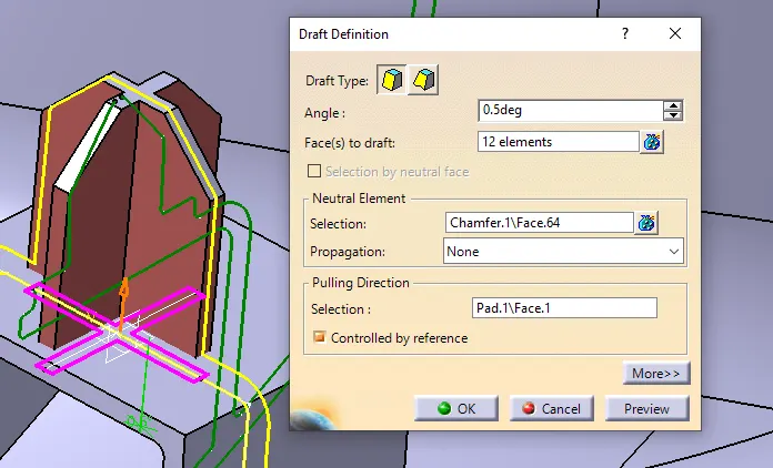
- Add Draft angle to the faces of the 4 way locator with 0.5degree draft angle. select the base as neutral element and tooling axis as draft direction.
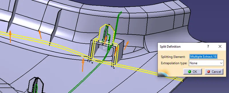
- now split the dog house with the multiple extracted surfaces for the removal of sink marks.
- insert a geometrical set for Lifter tooling axis. create a line through the point perpendicular to the main tooling axis with reference from the mastersection
- Draft the inner surfaces of the dog house with 0.5 degree draft angle and Lifter tooling axis as pulling direction.
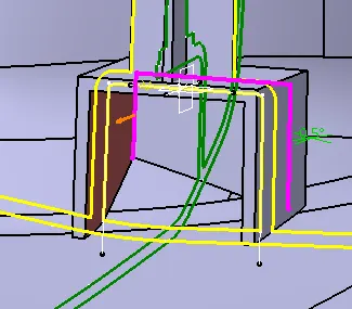
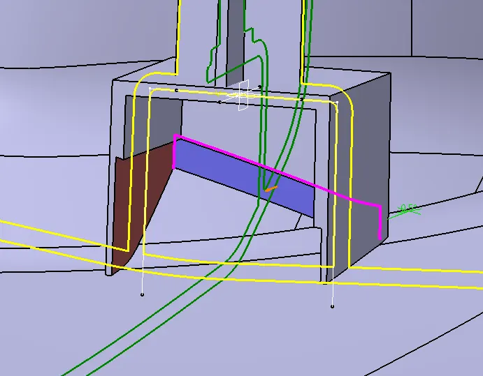
- Add Edge fillets with 1mm to the edges of the drafted faces inside the doghouse.
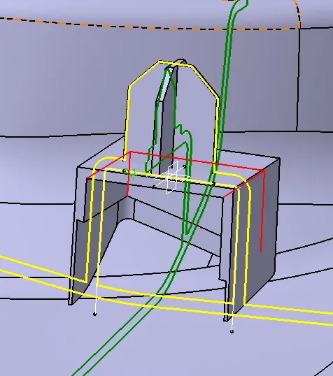
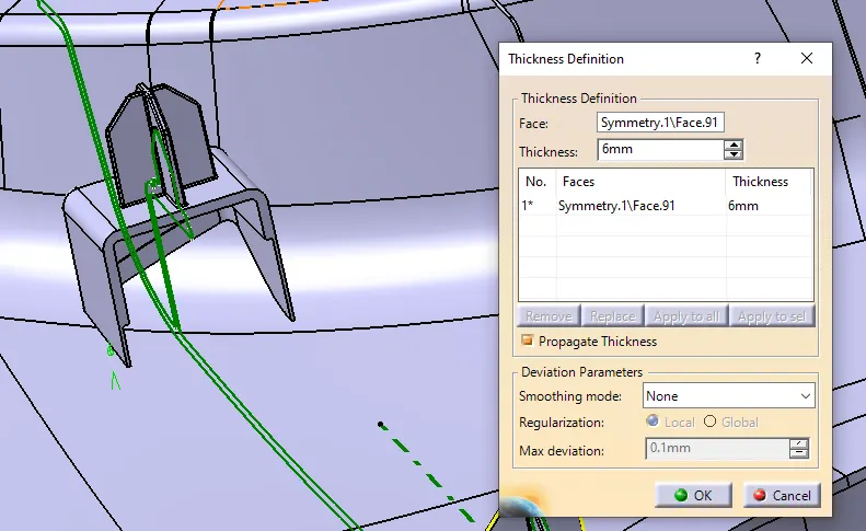
- use Boolean operation Unitrim to trim the dog house with 4 way locator . now using the copy and paste specials.. method replicate the trimmed part body to th emain folder. using translate command replicate the dog house with 4 way locator to the plane created. also thicken the base surface for the translated body with6mm accordingly. using Boolean operation ADD them to the main part body.
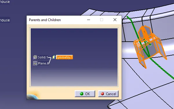
- RIBS are created at equal intervals. insert a geometrical set for the ribs creation. create a positioned sketch from the master section as reference. maintain 50mm of gap between two ribs.
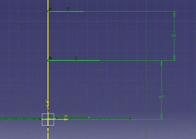
- Exit the sketch and extrude the sketch 20mm in both the limits, now off-set the class-B to 20mm and extract the boundries with multiple extract option. using points repetetion with plane create multiple equidistant (50mm) points on the extracted boundry .
- similarly perform the same procedure on the other side of the pillar.
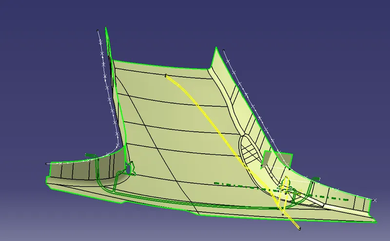
- now insert a part body for the Rib created. thicken the rib surface with 0.4mm in both the limits ie.. 0.8mm. split it and draft the faces of the surface with 0.5 degrees and neutral surface as the base twoards the class-B surface select the lifter axis as pulling direction . also add edge fillet of 3mm radius.
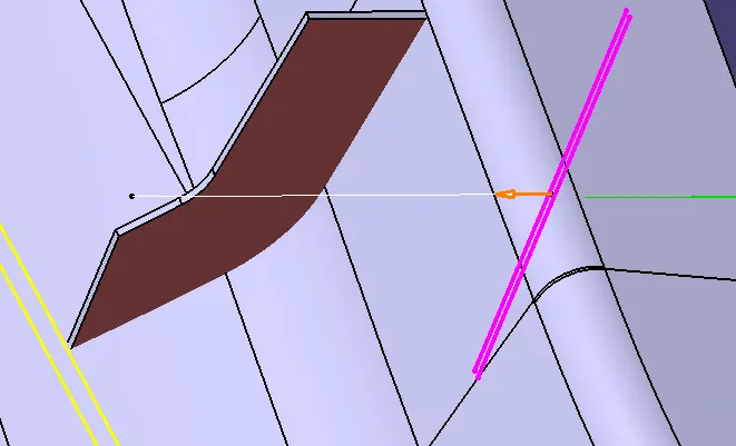
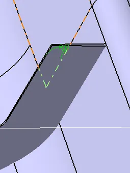
- Now using the copy and paste specials.. procedure replicate the rib part body and translate with point to point option and select the repeated points on the extracted boundry. perfrom the procedure for all the other points. later using Boolean operation ADD them to the main part body.
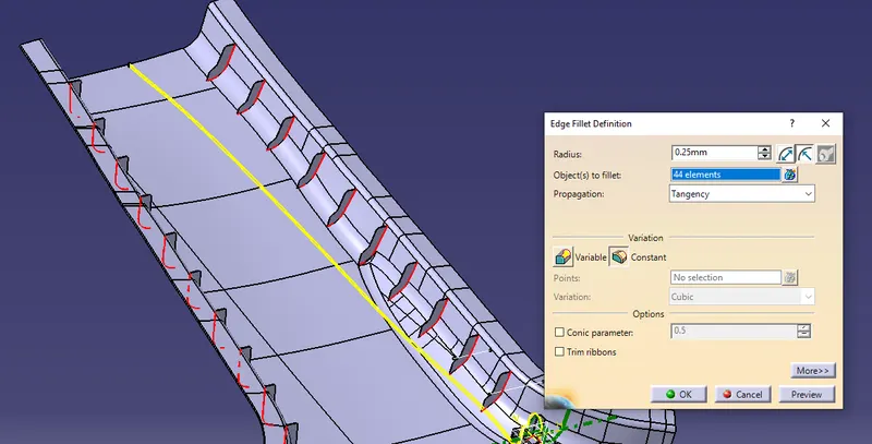
- Add edge fillets for the edges joining the ribs and class-B surface.
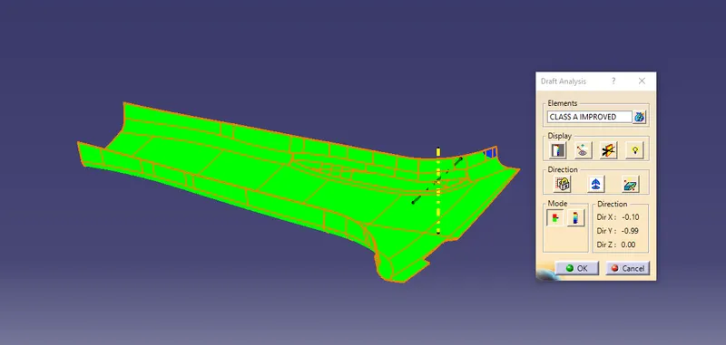
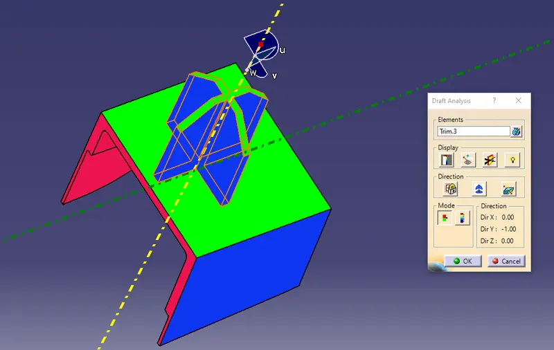
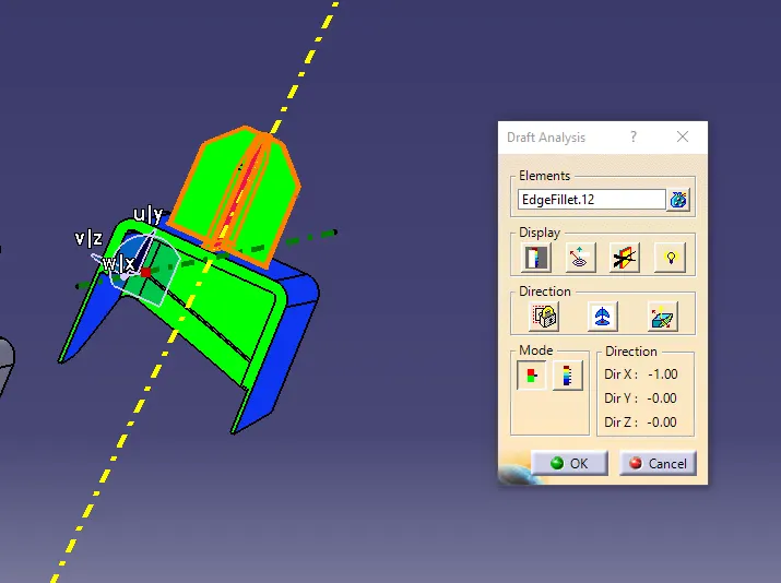
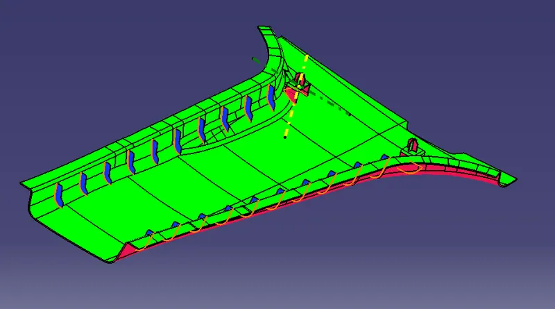
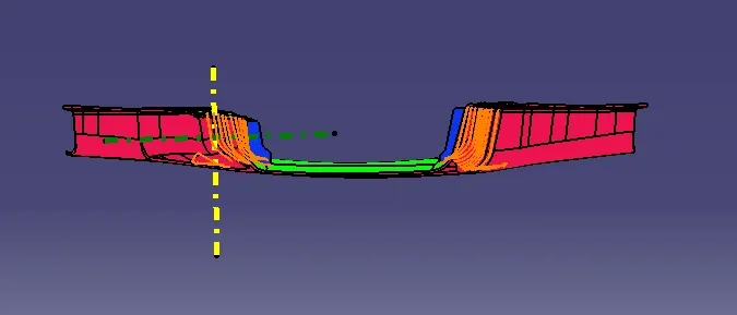
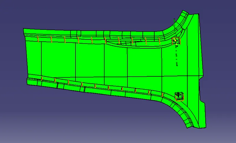
- Now perform the Draft analysis on the given class-A surface. unhide the main tooling axis. Goto insert- analysis- Feature draft analysis. select the component, drag and place the compass on the tooling axis and check for the colour deviation. 3 degrees in the draft angle. viewing from the tooling direction the surface must be in green colour. the surface opposite from the toolimng direction is represented in red colour. drafted surfaces are view in blue in colour.
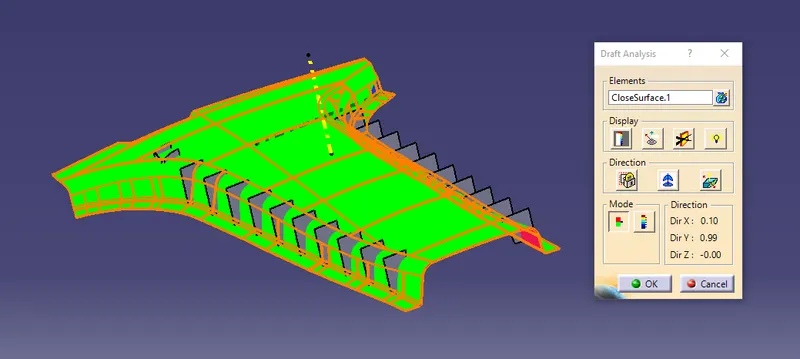
- Similarly perform the draft analysis on the B-pillar. Dog house with 4 way locator both in main tooling axis and lifter tooling direction
Model Tree :-
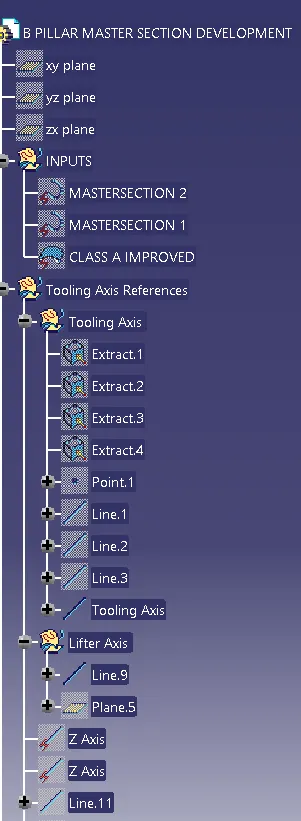
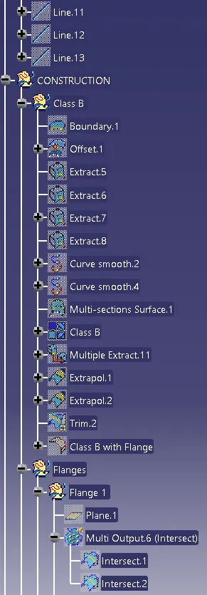
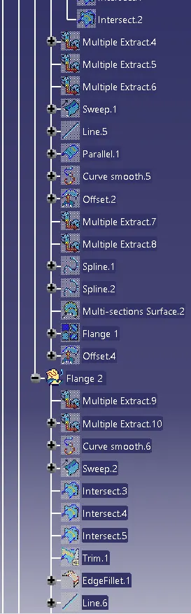
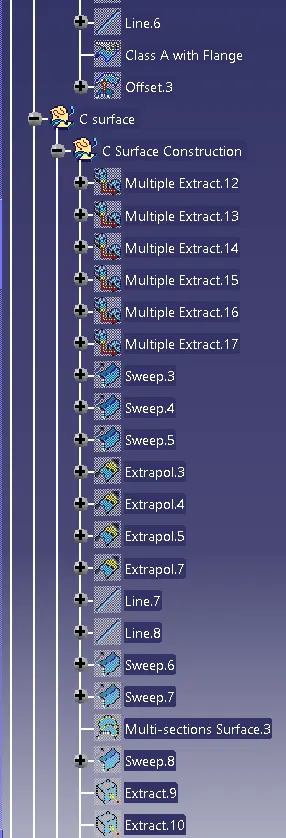
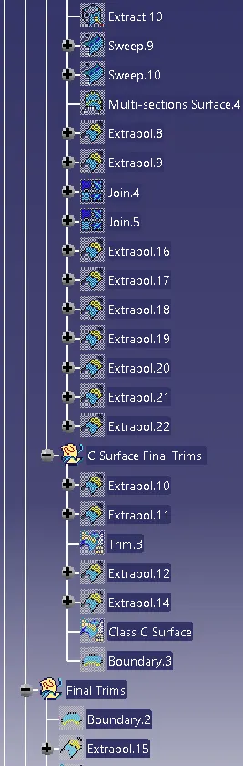
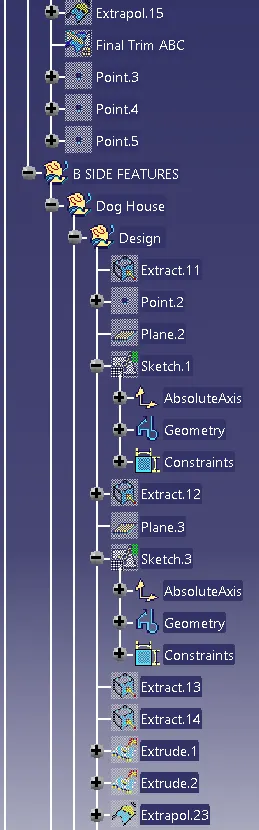
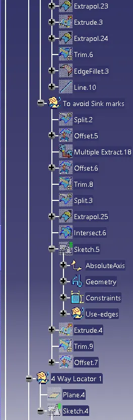
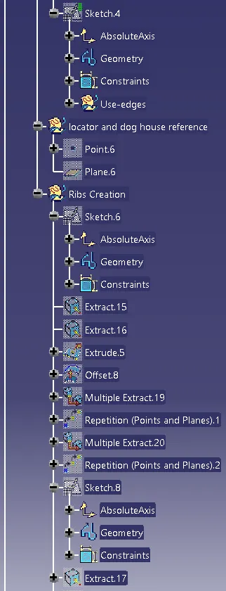
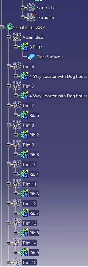
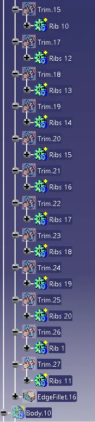
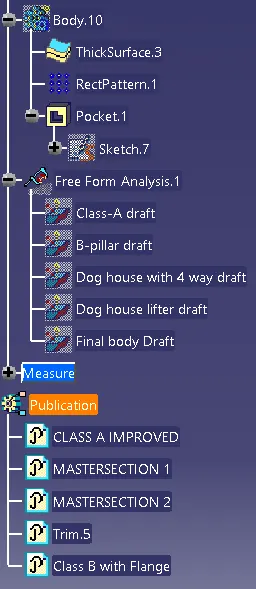
- Use publication to publish the creations inorder to easily view them in the tree structure. follow the design guidelines while creating the dog house or 4 way locators. insert a separate geometrical sets or part bodies to differentiate them in the tree structure.
Result :-
Isometric view -
Front view -
Top view -
Bottom view -