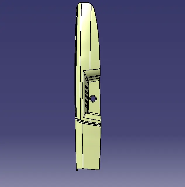
Door Arm Rest Week 8 Challenge
Aim :- Creation of a Door Arm rest with the reference of given Class-A and thickening it. also perform draft analysis to the given component.
Procedure :-
- the given component is a Class-A surface . check for the gaps in between the surfaces which are not desirable. select boundry option to easily visualise the surface boundries .
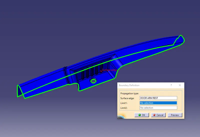
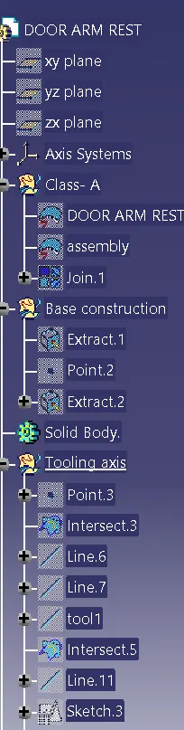
- to create a tooling axis for Class-A , insert a geometrical set and rename it as tooling axis creation. analyse the surface and create a point in the cavity section by extracting the points and creating a mid point between them.
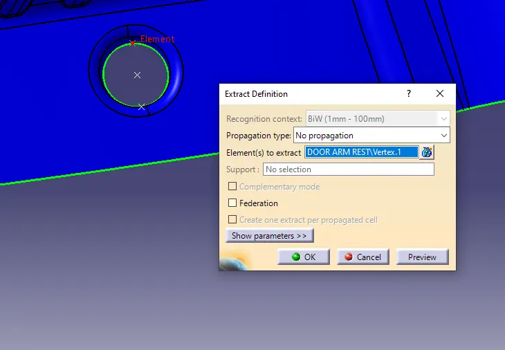
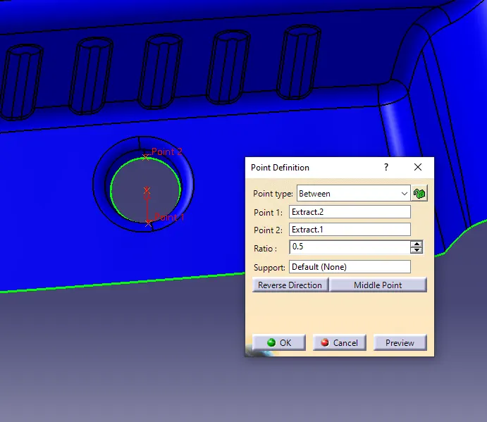
- through that point insert a plane in ZX- direction and intersect the plane with the surface to form a intersection lines on the surface through the plane.
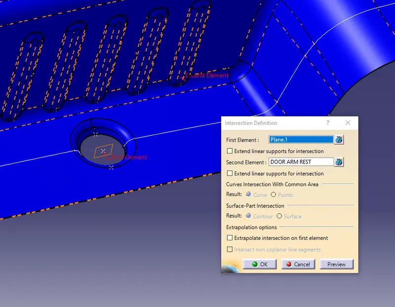
- extend the lines through point-point option in the lines and bisect them to create a bisecting line.
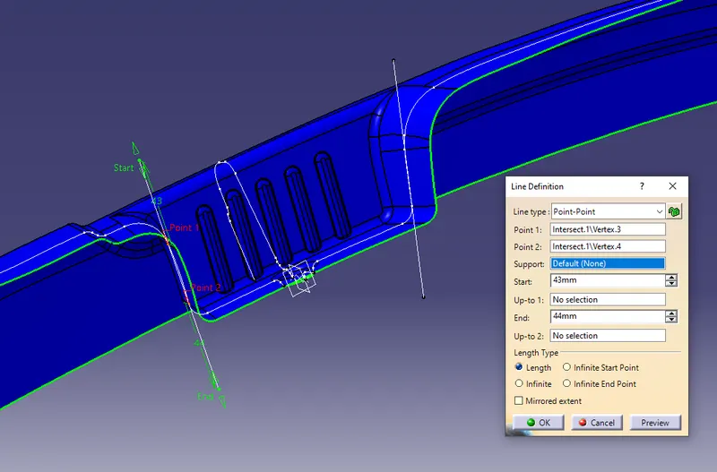
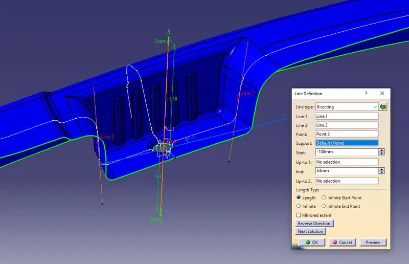
- similarly create another plane on the perpendicular direction with the plane. and bisect it with the class-A surface. similarly extend the lines with the point-point option and bisect it with the reference line created in zx-direction. a new bisecting line is created , rename it as tooling axis-1.
- perform draft analysis through the tooling axis created.
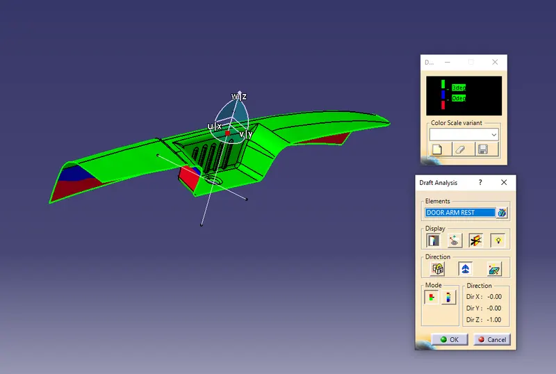
- since the cavity part is not having the required draft angle. a secondary tooling axis is created in the sliding direction. adjust the compass according to the required draft angle for the cavity section and lock the compass. create a line parallel through the compass and redirect the direction of the line with the compass and unlock the compass and reset the tooling axis.
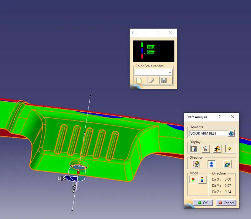
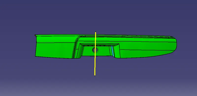
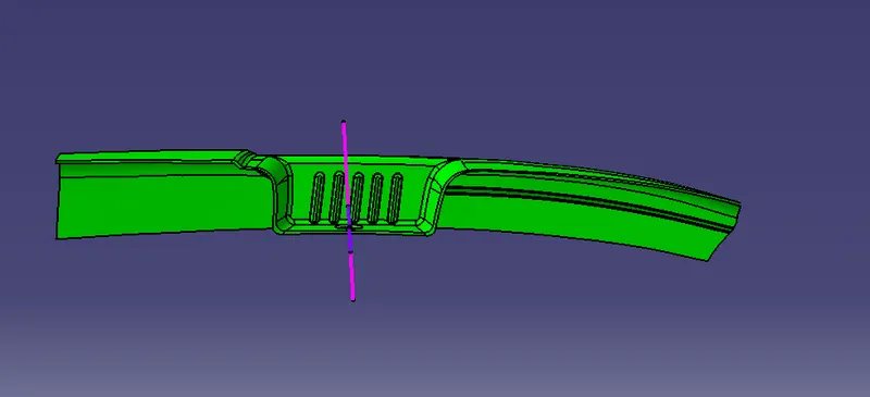
- now the draft angle is set through the two tooling axis created. in both the top and sliding directions .
- now class-B surface needs to be created with the reference from the given Class-A surface. insert another geometrical set and rename it as Class-A
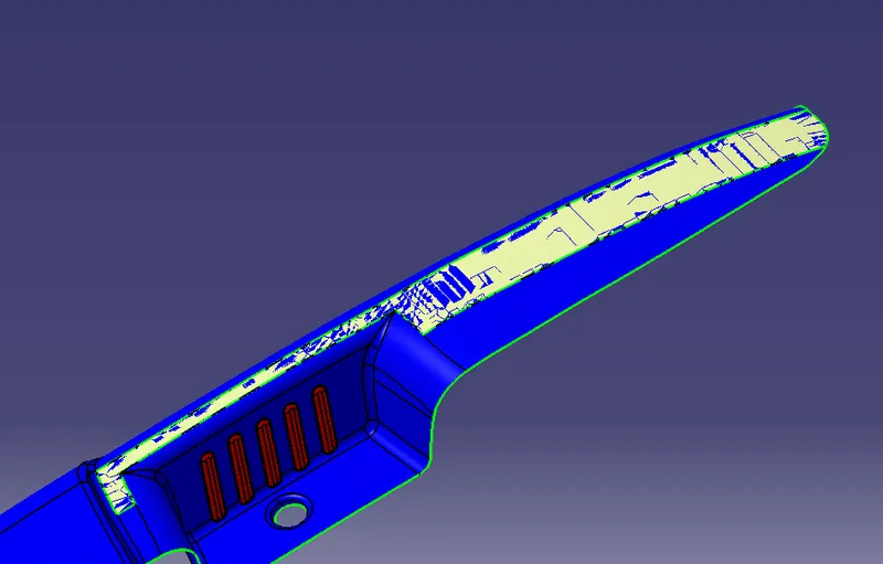
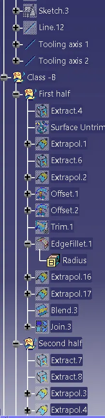
- extracrt the top surface of the class-A and hide the main surface untrim it and extrude the surface only if it is flat. surfaces with angles should not be untrimed.
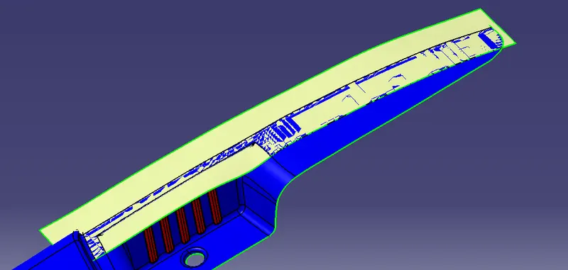
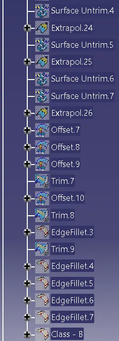
- similarly extract the other perpendicular surface and untrim the surface .now offset them with 2.5mm thickness from the Class-A surface. and extrapolate if they are not intersecting or joining. then trim the required portion of the surfaces with the reference of class-A.
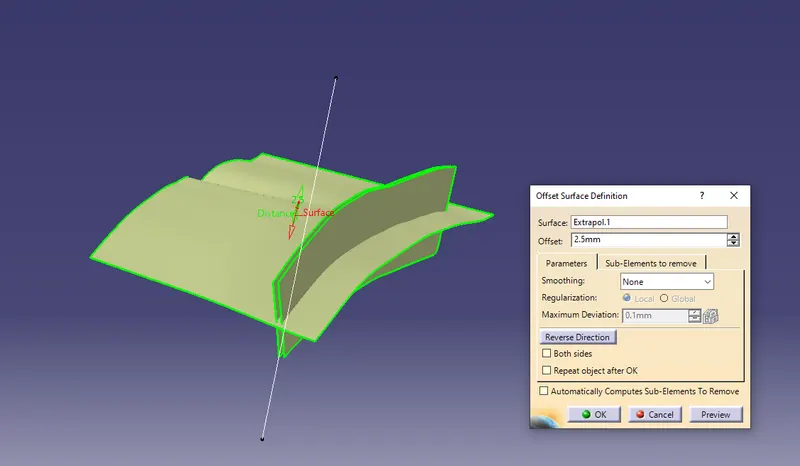
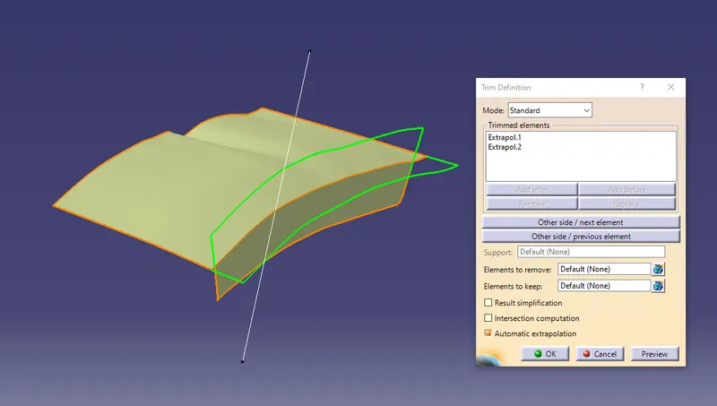
- give a fillet at the edge by measuring the fillet radius from the class-A . substract the thickness value from the radius.
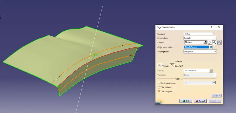
- now extract the other other two remaining surfaces of the upper section and follow the same procedure. untrim- extrapolate if needed - off set , and trim them together. add a fillet with the required thickness.
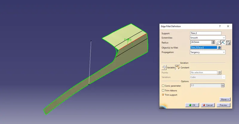
- compare the two trims with the Class-A and make sure they are off-set properly from the class-A surface. now to create the fillets region between the two trims is complex.
- create a point on the fillets region and add an axis system to it.
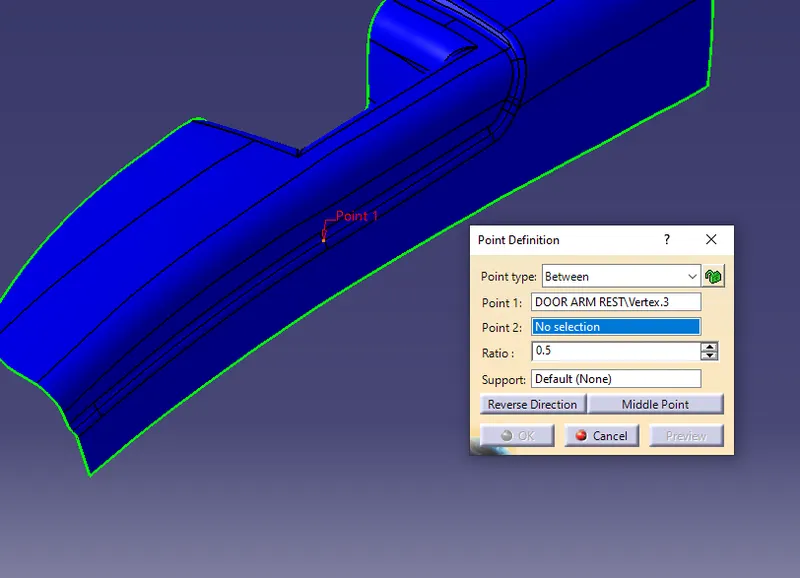
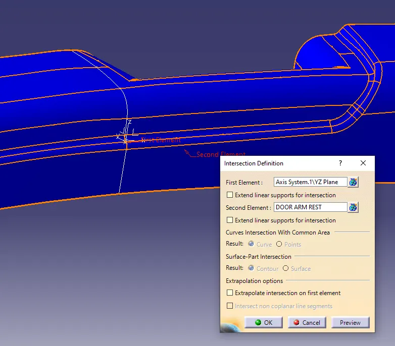
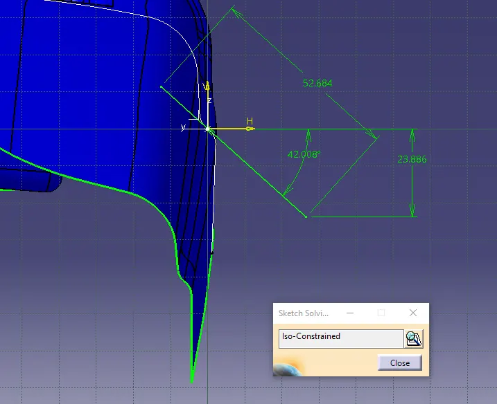
- intersect the YZ-side with the surface to get the intersection lines on the surface . now create a positioned sketch with reference of the axis and point created. draw a line and make it tangent with the axis. also make sure the line is iso-constrained. now exit from the sketch and hide the intersection lines.
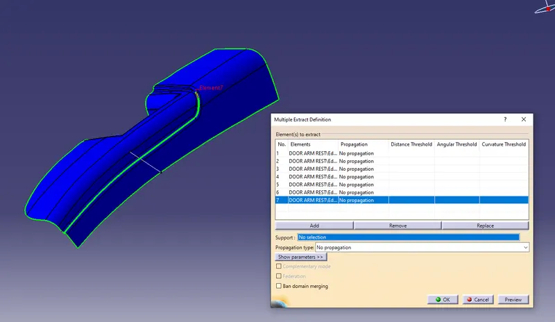
- extract the edge lines between the fillet region using multiple extract or boundry using no- propogation option.
- after extraction. use smooth curve to clear the curve into one single curve.
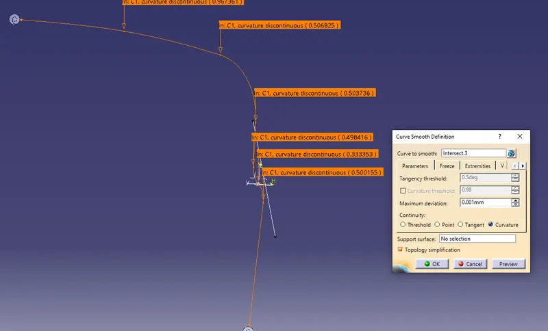
- make sure the curve is moothened in curvature option.
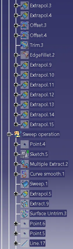
- now using sweep option sweep the curve with reference of the line created through sketch.
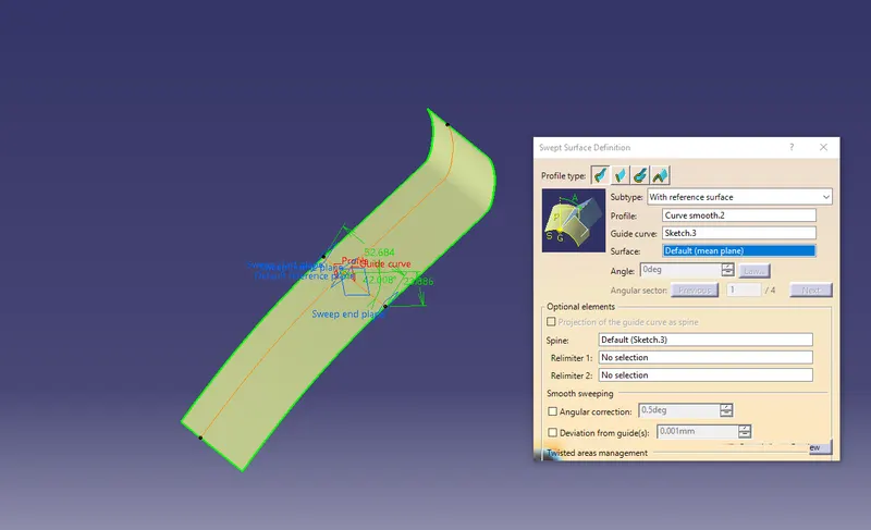
- now off-set the sweeped surface with required thickness value and compare the three surfaces with the Class-A surface.
- similarly extract the other side remaining of the fillet regiona and untrim the surface and extrapolate if needed. off-set that surface with the given thickness value. now create a spline with both the fillet region surfaes and using the multisection solids fill the surface between them
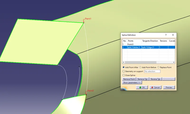
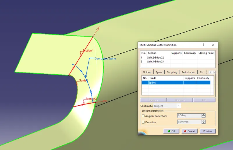
- join the fillet region surfaces together. now unhide the upper surfaces and trim all the three formed surfaces. use extrapolate option to intersect them before using Trim.
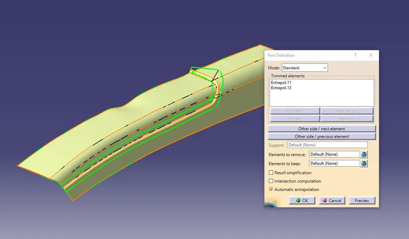
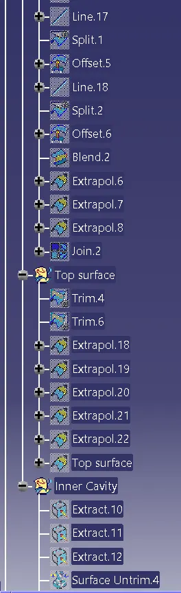
- the top surface is created
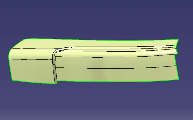
- extract the side walls of the cavity section and untrim them. extrapolate if needed. then off-set them with the thickness valus away from class-A surface.
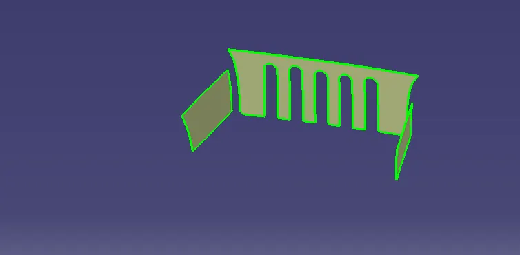
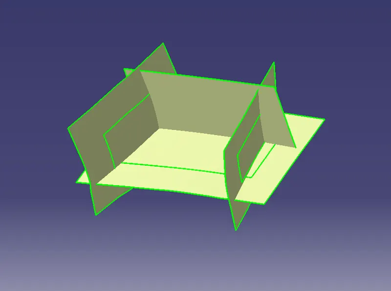
- now trim the off-set surfaces with the reference from class-A . and trim the upper surface with the side walls (cavity section) .
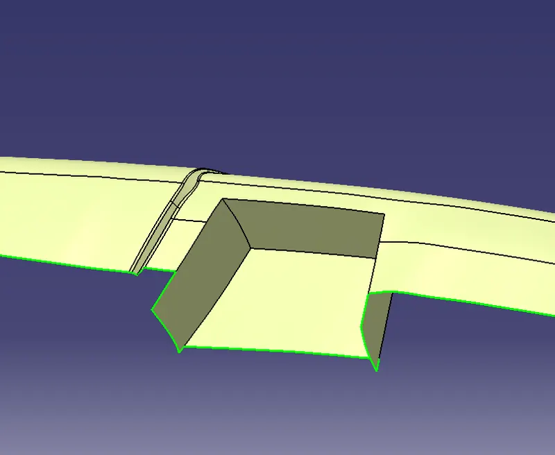
- after the trim , measure the fillets section on the class-A, if the fillet edge is improper and cannot be measured extract the surface from the class-A and extrapolate it and then measure the fillet radius.
- measure the fillet radius according to the thickness of the off-set and give the value according to it.
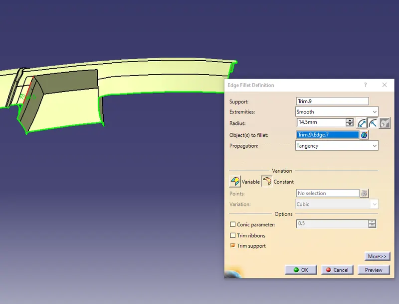
- after creating the fillets. join the surfaces. Class-B is created using the reference from the class-A surface.
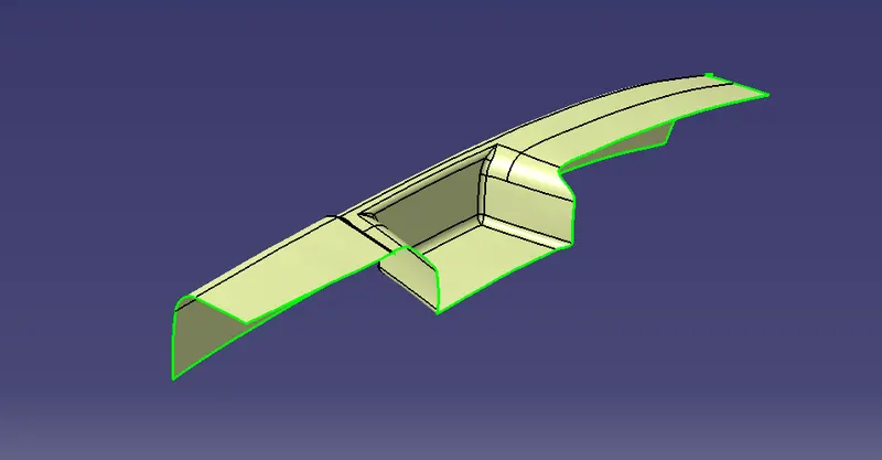
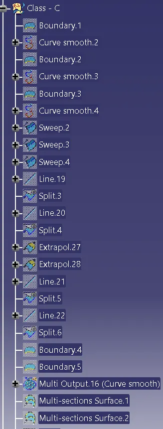
- now unhile the class-A surface to create the class-C surface using the boundries . using multiple extract of boundries option extract the outer boundry of class-A with tangent propogation and no-propogation if needed. and use curve-smooth to clear the cuve section properly.
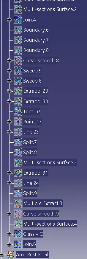
- using sweep option sweep the created curve independently. extrapolate and trim the sweeped surfaces if they are not intersecting or joining.
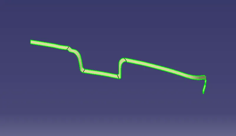
- similarly sweep the other parts of thecurve and trim /join them together. compare them with the calss-A surface.
- class-C surface is created using the class-A boundry as reference.
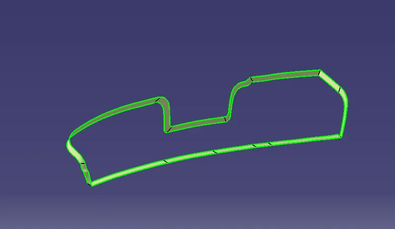
- trim the class-C with the A,B surfaces and join them to get the cloed surface. to make sure the surfaces are properly closed. use boundry option and select the surface which shows that the surface boundry cannot be created as the surface created is closed.
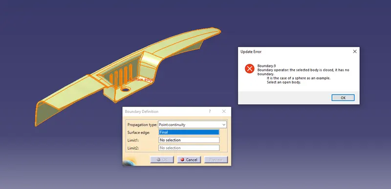
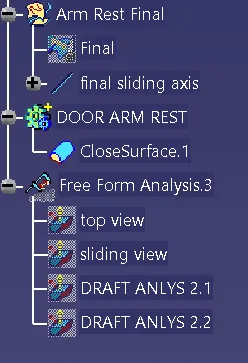
- now Goto mechanical design - part design and select the fille surfaces to create a solid body out of the class-A,B &C.
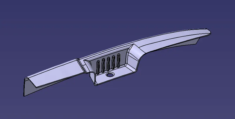
- now perform the draft analysis on the surfaces. unhide both the tooling axis and Goto - insert - Analysis - Feature draft analysis.
- select surface and place the compass on to the upper tooling axis and visually analyse the surface. similarly plase the compass on to the sliding tooling axis and clear the part for cavity section.
Model Tree -
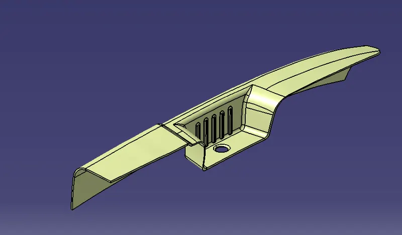
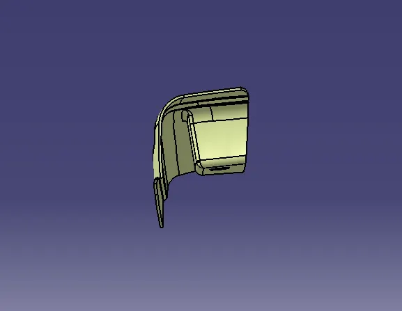
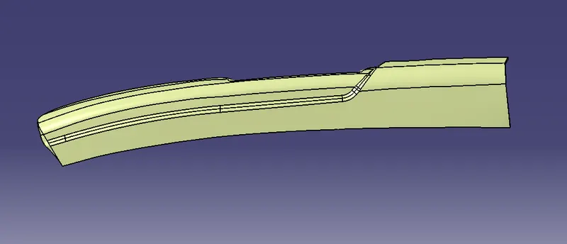
Result :-
Isometric view -
Front view -
Side view -
Top view -