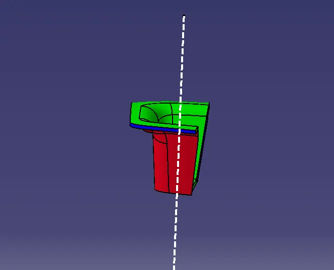
Week 8 - Challenge 3 - Switch Bezel Design
Aim :- To Create the Switch Bezel Plastic component through the given Class-A surface, the tooling axis for the given Class-A Surface is created meeting the requirements of the draft angle and at the end perform the Draft analysis on the model.
Procedure :-
- check for the Gaps in the middle of the given class- A surface by selecting the boundry option. any gaps in between can be easily visualised through this.
- perform draft analysis for the given Class-A surface.
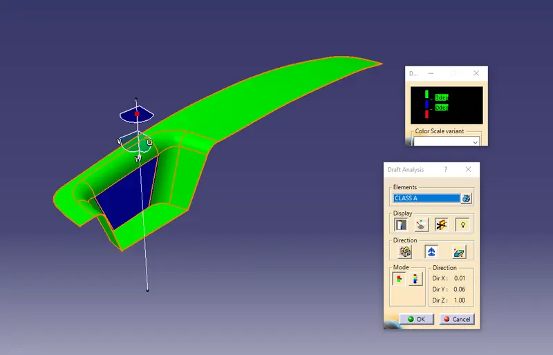
- create a new geometrical set for tooling axis creation. extract the base surface from the given class-A and create a point on the surface and create a plane with reference to it in the Y-Z direction.
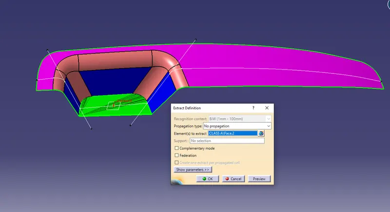
- now intersect the plane with the class-A surface which shows the lines of intersection on the surface. through the point-point method extract the lines on bothe the side wall surfaces and extend them enough .
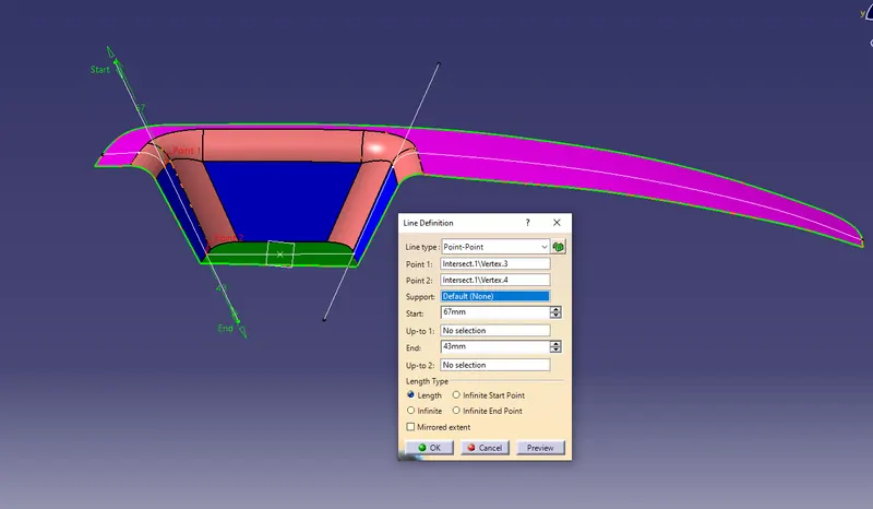
- now select the two lines and create a bisecting line through the point as base.
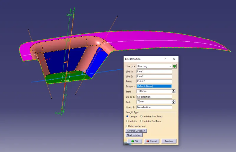
- now similarly create the bisecting lines through the point and plane reference in the Z-X plane direction. extend the lines similarly through point-point method and bisect them.
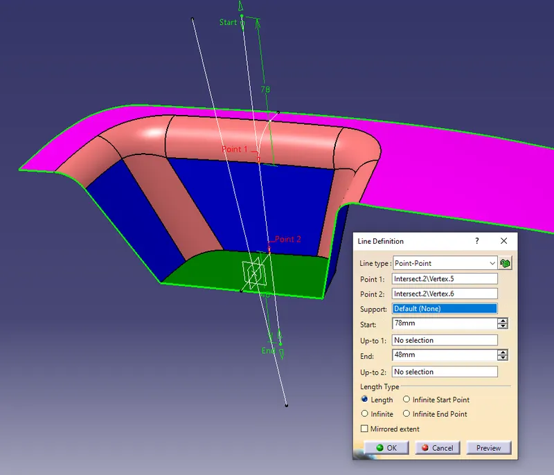
- two bisecting lines on both the directions are created for reference , now bisect these two lines to get a final line and rename it as tooling axis.
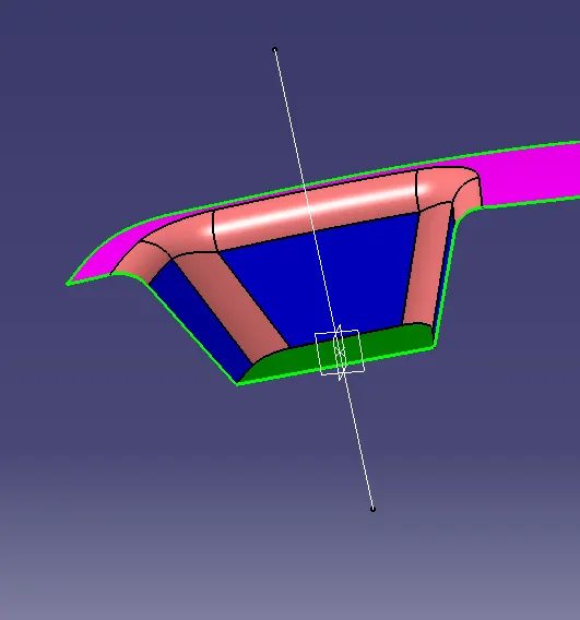
- insert a new geometrical set and rename it as Class- B . in order to create class-B ,, the given class A is taken as reference.
- extract the upper surface using extract option and Untrim it with no-propogation option. extrapolate if needed.
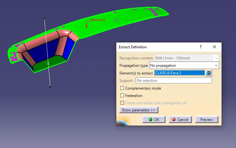
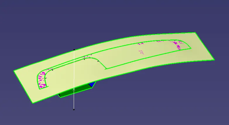
- similarly extract the side wall of the the class-A and untrim them using no-propogation method. extrapolate(point continuity) the surfaces if they dont intersect eachother ( causes error while trimming them) .
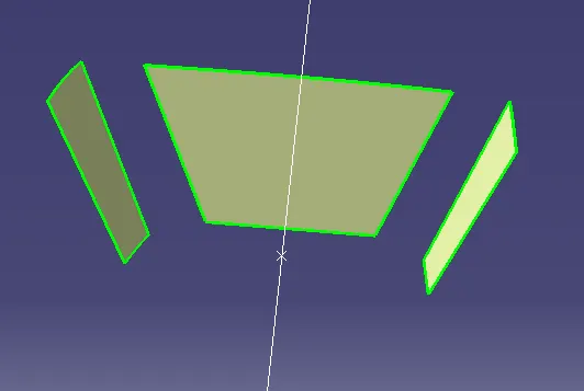
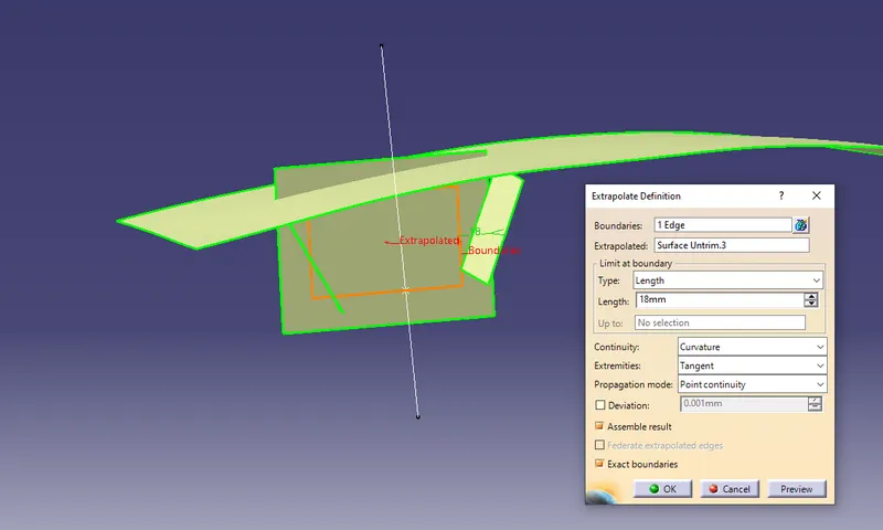
- now off-set the upper surface to 3mm below the class-A surface and similarly off-set the side walls with 3mm outwards the class-A.
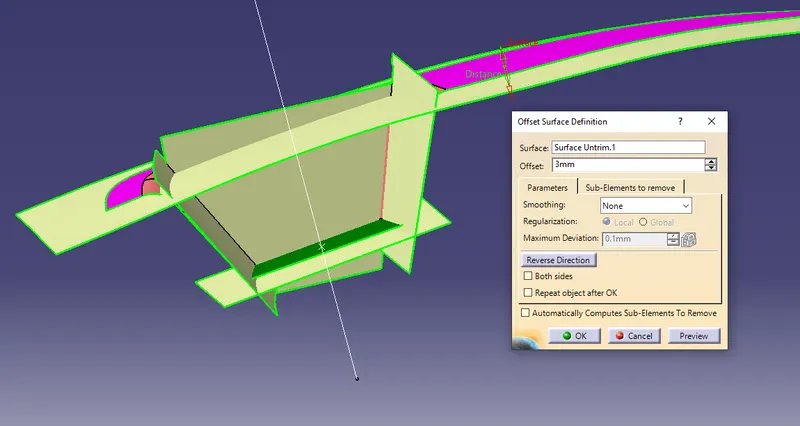
- now all the four surfaces intersect with eachother. similarly unhide the Base extracted during the tooling axis creation and use it to untrim and extrapolate it.
- off-set the base surface to 3mm below the main surface,
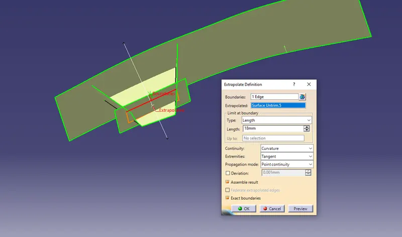
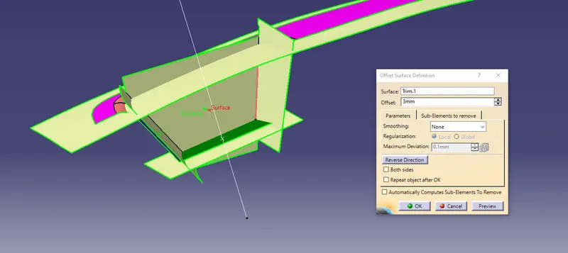
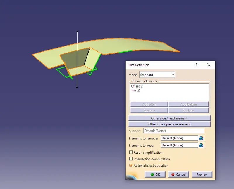
- after getting the upper surface, side walls , base surface. trim them according to the class-A as reference.
- create the fillets at the required edges using edge-fillet option. the fillet radius is measured using the measuring tool. if the fillet has non-uniform corners. extract the fillet region from the Class-A and extrapolate it and measure the radius. if the fillet on the class-A is closing towards class-B then the radius value is taken as :- outer radius(class-A) - offset value.
- if the fillet is closing away fron the class-B the fillet radius on class-B is taken as :- inner radius (class-A) + offset value.
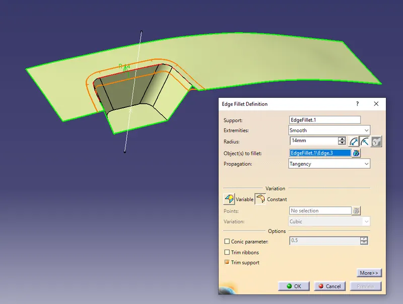
- now after creating the fillets, class-B surface is formed with referrence of Class-A and thickness of 3mm.
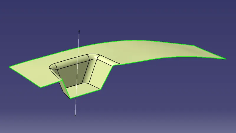
- now for the creation of Class- C again Class-A is taken as referrence. extract the boundries of class -A ( extract them using multiple extract option or boundry option individually).
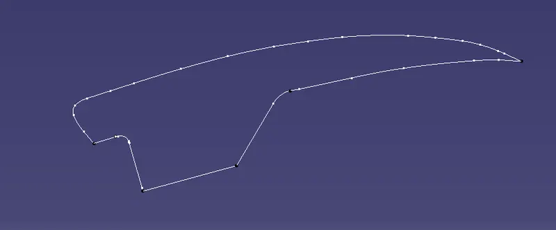
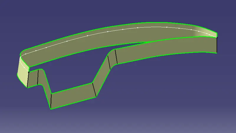
- using sweep option with 3 degrees as draft angle and outer draft direction, using tooling asix as reference sweep the boundaries separately.
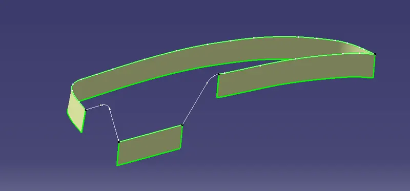
- some boundries with angles are sweeped by extrapolating the joining surfaces and joining them. and splitting the surfaces with a line according to the line of sweep and joining them, extrapolated surfaces are trimmed.
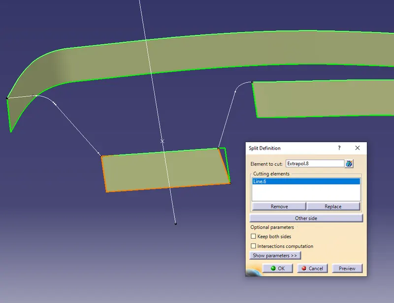
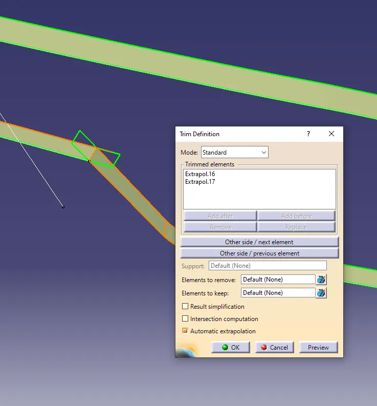
- now the Class-C surfaces is created using the sweep option through the boundries of class-A as reference.
- now unhide and join the class-A & B surfaces . and trim the A,B and C surfaces together to get the closed surface.
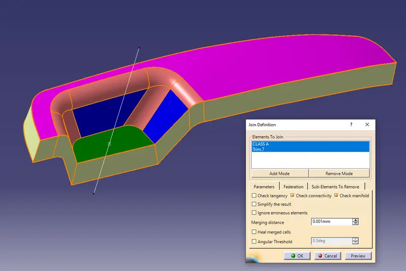
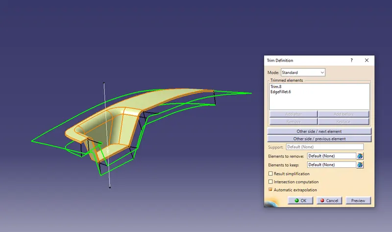
- make sure the surfaces are closed together with no unwanted gaps are boundries in between the surfaces. this can be checked by using the boundry option . if there is any minute error in closing the boundries use the merging tolerance as 0.003mm .
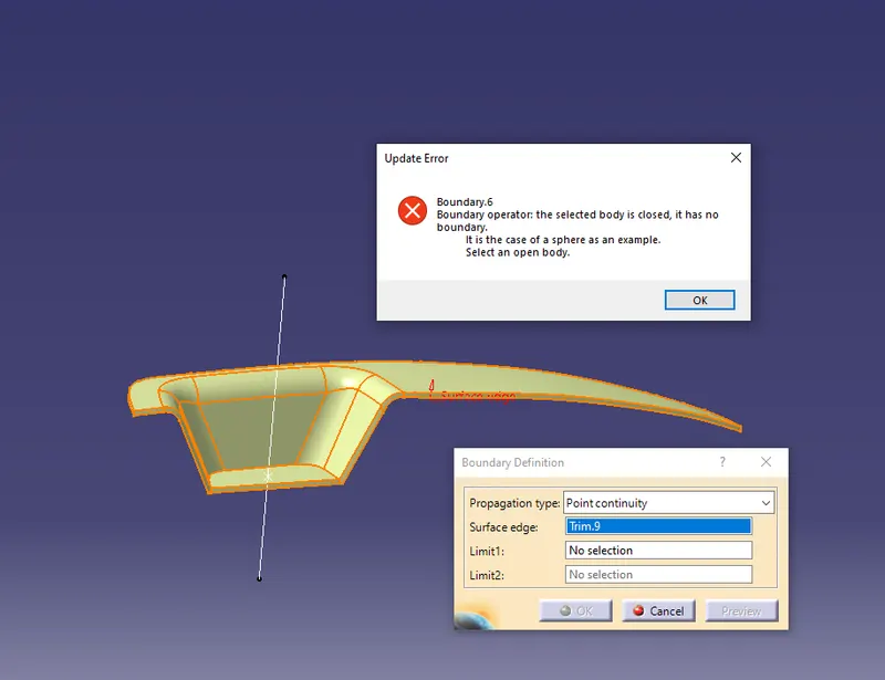
- now Go to part design and use fill surfaces command to create a solid body out of the created surfaces. and define it on the separate part body.
- make sure to insert separate geometrical sets for differentiating the creations and rename them accordingly.
- perform the draft analysis Goto Insert - Analysis - Feature draft analysis. select the surfaces and set the draft angle to 3 degrees and place the compass on the tooling axis created.
- check for the colour variations and adjust the tooling axis accordingle. create another tooling axis in required direction with reference of the compass angle to get the accurate tooling axis .
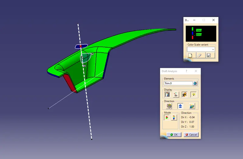
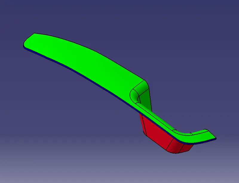
- the draft angle is differentiated by using colours. GREEN - >3 degrees , BLUE - 0-3 degrees , RED - <0 degrees
- publish the class-A ,B & c surfaces and tooling axis to easily view them from the tree structure.
Model Tree :-
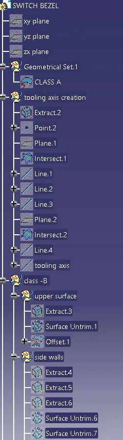
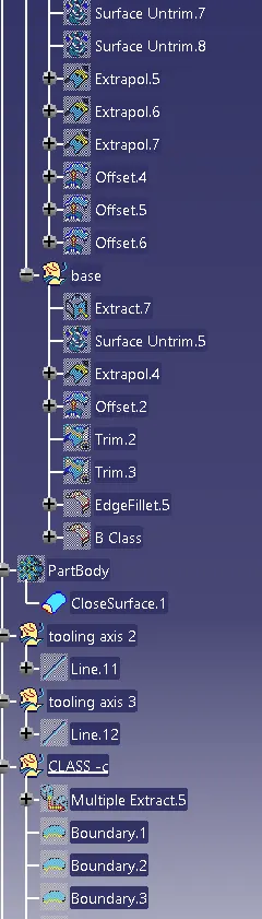
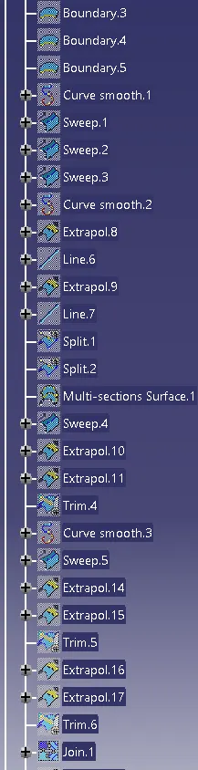
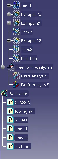
RESULT :-
Isometric view -
Front View -
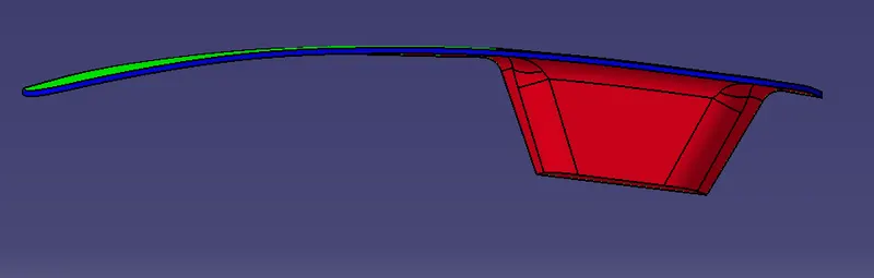
Top View -
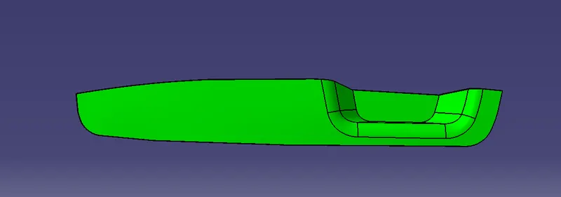
Side view-