Week 9 - Project - Master Section Development
B Pillar Plastic Component
Aim: To create B pillar Plastic component from a given class A surface also, create B side feature like Rib, locators, doghouse and validate the design by doing draft analysis.
Objectives:
- Creating a tooling axis and following design rules.
- Creating class B and C surface using class A surface as input
- Following the master section to create flange
- Following the master section for thickness and to create closed volume.
- Following the master section to create attachment features.
Introduction:
B Pillar
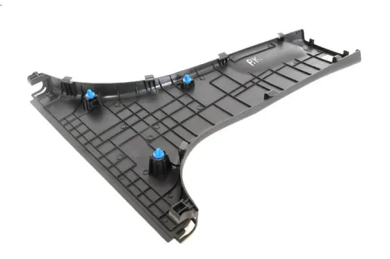
The B pillar is the central pillar of the car. This pillar is actually a sheet metal part which is welded in the BIW of the car. The B pillar trim is attached to the B pillar and improves the aesthetic look of the car. Mostly the trims are manufactured by the injection molding process. The design of the B pillar is carefully done to make the part manufacturable and usable in the interior. While manufacturing a part through injection molding a lot of defects can occur on the plastic part which will destroy the look of the panel. The design has to made in such a way that all the errors can be rectified.
What is master section?
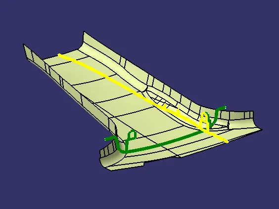
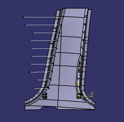
Master section is nothing but a guideline for the required design, that means the component is already designed, styled and concept. But in master section reversed engineering is applied the component is located using the guided lines, according to the design required and then it is manufactured. The below fig shows the class A surface with master section.
OVERVIEW OF DESIGN LIFE CYCLE AUTOMOTIVE INDUSTRY:
- Concept Sketches: Concept sketches are rough idea of free hand sketches obtained through styling team and will be used to prepare the model. it is usually done through pen and paper and through the painting software. This will be used to generate the concept for preparing the model by incorporating various styles and information obtained through stakeholders.
- Class A Creation: After finalizing the concept the sketches are usually worked in software’s such as Autodesk alias to create class A surface.
- Clay modelling: The class A surface is concurrently worked by clay modelers to brainstorm and benchmark the styling of the product and letter the concept is validated by ringing up a rough clay model and then it is passed on to the design team for the preparation of New Product Design (NPD) CAD.
- NPD CAD: this were the development of surfaces to parts in CAD kick off and design engineer involvement is vital in this stage. The designers will work on the input class A surface which are validated from the feasibility team.
Procedure:
Procedure followed in creation of plastic New Product Design are:
- Tooling axis
- B surface Creation
- C surface creation
- Closed body creation
- B side surface creation
- Side core axis creation
- Draft analysis
Initially we got the Class A surface as an input for B pillar along with master section. So now surface quality and continuity is checked using the boundary option or the join command as suitable. If the surface is continuous without any break we can go for further procedure and if not, we have to update that surface locally using multiple extract and multi section solid commands.
Creation of Tooling Axis:
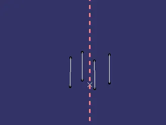
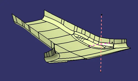
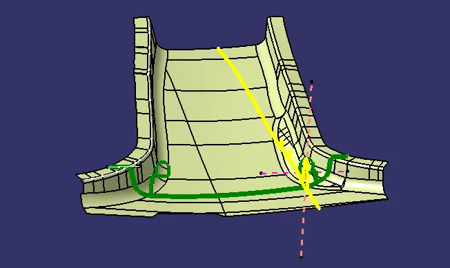
The above selected lines are extracted from locator and doghouse master section and the center point is created using point command, then the lines are bisected diagonally. Finally, two center lines are formed they are bisected with each other and a final line generates that is our tooling axis as shown in fig below.
In B pillar model there are two tooling Direction one on Main Tooling and other on Lifter side that is used to eject part during injection molding.
Creation of Flange:
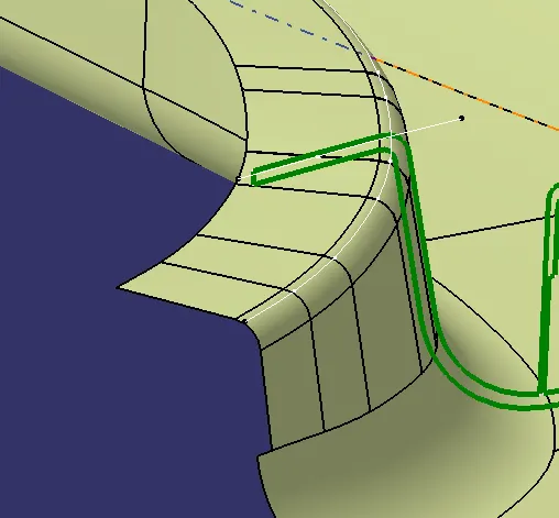
On referring the master section, it has been concluded that there are some flanges which are on the edges of class A surface.
By extracting the edges of class, A and sweep those edges at specific degree according to master section. This operation is followed on both the side of walls and refereed as flange1 and flange 2.
Creation of Class B surface:
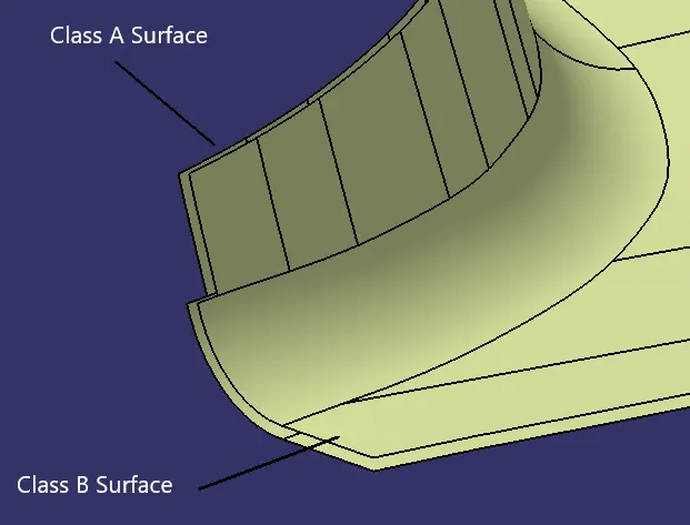
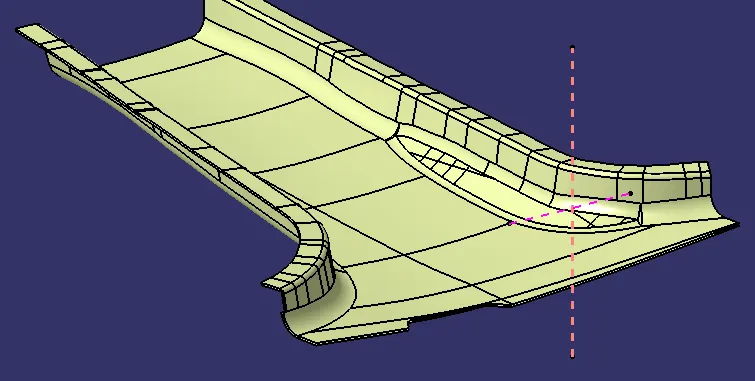
To create class B surface, select class A surface with flanges and offset it to 2mm. after offsetting the surface, we can observe that the class B surface is having a patch/missing surface. this surface needs to be fixed by manually creating a surface.
To create surface over the patch, we first need to extract boundaries of that edges separately and using the ‘Multi section’ command a new surface can be created. Now join the patch surface with the offset surface to form a Class B surface.
Creation of C surface:
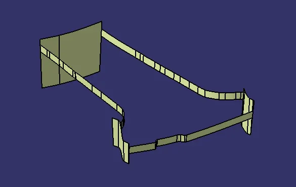
class C surface is swept along the boundary of class A at an angle perpendicular to the class A surface with respect to the tooling axis direction with a draft angle of 3 degree.
Joining of Class A, B and C surface to get a closed Surface
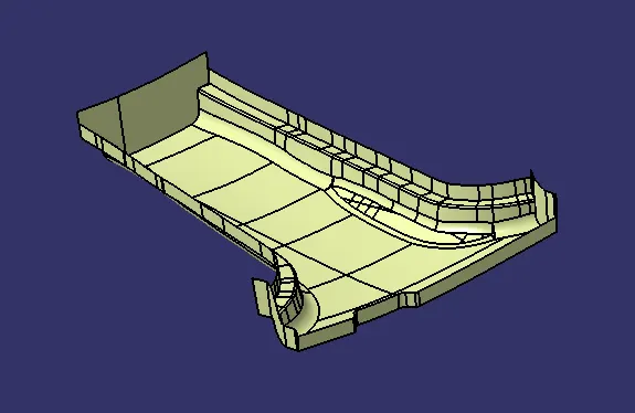
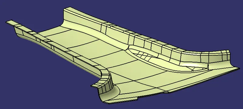
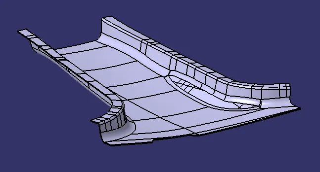
After finishing all the 3 surfaces, join the class A and C surfaces together using join command. Now, the joined surfaces are trimmed with B surface to get closed surface. the closed surface is then used to create the actual part body using solid features.
Attachment Features:
The attachment features are the fixation and location features that fixes the components. The common attachment features used in B pillar are:
- Dog House with 4-way locator
- Ribs
Dog House:
The Dog house is an engineering feature that is used in plastic design to support other engineering features like screw bosses, push pin clips, snap fits, locator pins.
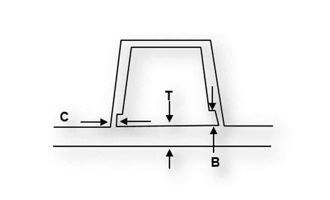
Design consideration for Doghouse
- Doghouse wall thickness at the intersection of the part wall (c) should be 40% or less than the main wall stock (T)
- Height of (B) should be between 3.0 – 6.0 mm
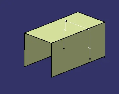
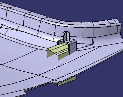
To create dog house master section has been given as input. The top surface and support walls of the dog house on which locator is laid is created by simply extracting the lines from the master section in a sketch and extruding them to a certain length.
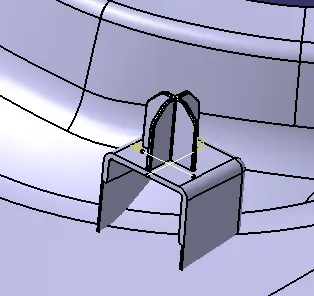
A locator is a gateway to make sure the parts we are putting together fit the way we want to fit. 4-way locator is created over the dog house. 4-way locators mean you prevent movement at 2 axes (+X, -X, +Y, -Y) on the plane.
A draft of 0.5mm degree is given to the locator and also a chamfer of 5mm at 45-degree angle is given to the top edges of locator.
Rib:
Ribs are created to strengthen a part without increasing thickness of the wall, because, less material is required ribs can be more cost-effective solution as well.
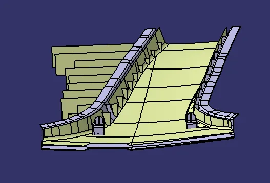
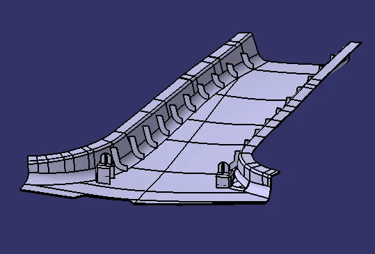
We create multi ribs which are 50mm apart first go to class A/B surface. Now copy the solid body of rib which we created and paste it in the main tree structure use the translate option the copied solid body of the rib can be moved from one point to another points. Offset class B surface to 10mm and trim the ribs with it removing the excess point and give a draft 0.3 to the ribs.
Draft Analysis of final Model:
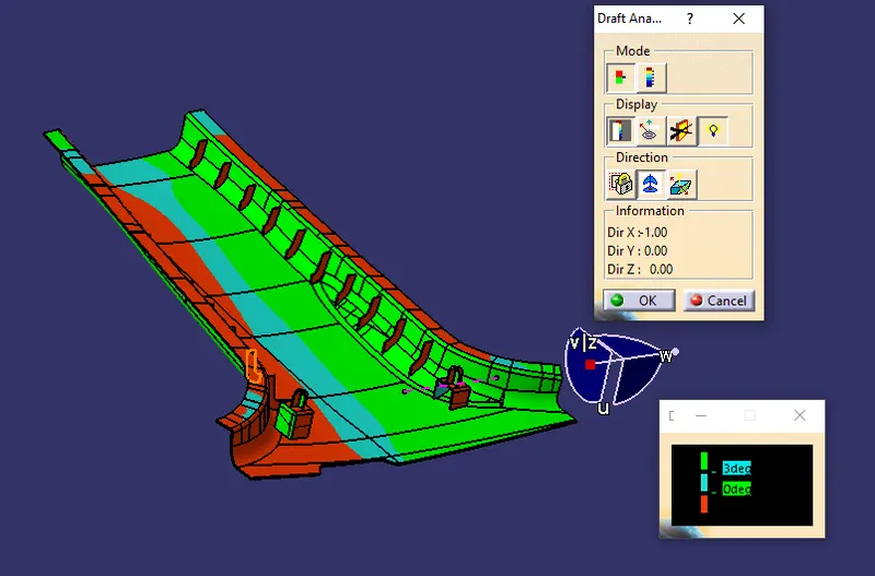
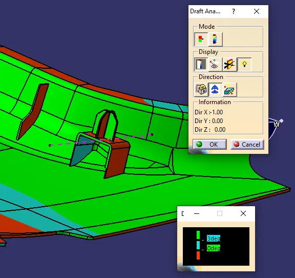
Draft analysis enables you to detect the part we drafted will be easily removed. This type of analysis performed on the base of color ranges identifying the zones on the analyzed element where the deviation from the draft direction at any points, corresponds to specified values.
- Go to insert
- Click on the compass icon and align it with the tooling axis and click on the surface, we will get our result.
Green color = 3 degree and more than 3 degree of angle
Blue color = draft angle between 0 to 3 degree
Red color = draft value is zero object fails
Main Tooling Axis:
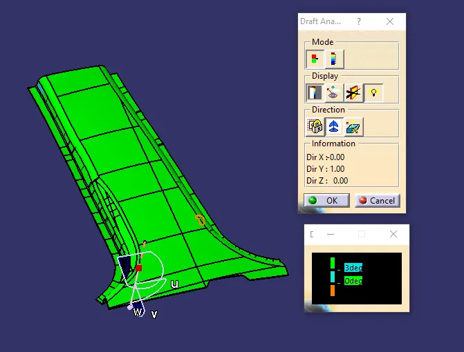
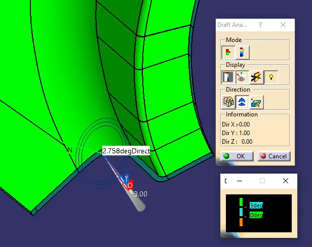
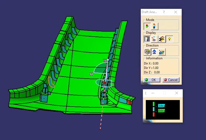
Area of class A which is highlighted in red colour needs to be change by class A styling team
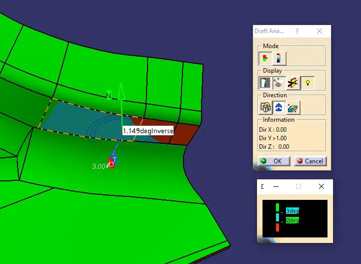
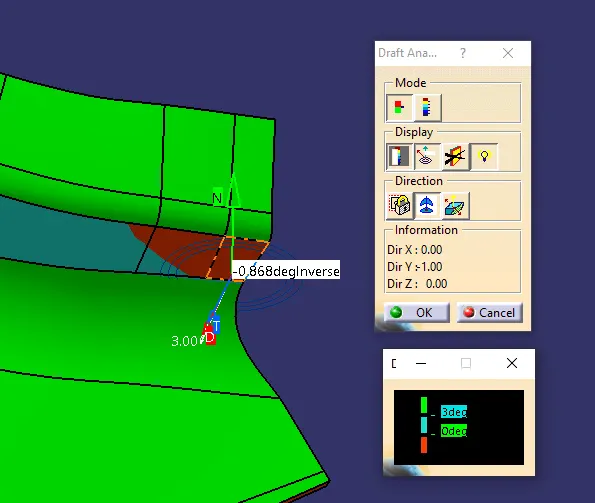
Lifter Axis:
Conclusion:
- Thus, class B and C surface are created as per automotive design standard using Catia v5.
- Draft analysis was performed for built model and it could be seen that the draft was under permissible limit for the manufacturing of the component.
- B side features were created for the component as per design rules.