Radar Mast & Final Assembly of Yacht
TITLE: Surface Modelling, Assembly and
rendering of Sunseeker predator yacht.
OBJECTIVES:
- Implementing various Surface design Tools, Sketching tools to gain hands on experience In modelling a complex design.
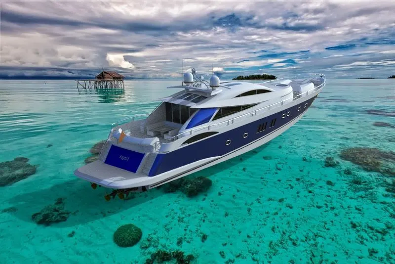
- To design, assemble and render the Sunseeker Predator 108 yacht.
- To learn solidworks software as a design tool In industrial manner.
INTRODUCTION:
In this project, I learned how to model a sunseeker predator yacht parts, Surface and Assembly workbenches of solidworks from scratch. The designing started with creating blueprint setup by setting various views with proper dimension and orientation. After that all parts Were assembled in assembly workbench and then rendered Using solidworks visualize. Sunseeker predator yacht is motor yacht. A yacht is Designed to emphasize performance over comfort.In this project my main focused on prime parts and designed Them. the parts I designed in this project are Radar, propeller, Hull, garage door, seats, Superstructure and Radar mast.
DESIGN METHODOLOGY:
- Modelling
- Assembling
- Rendering
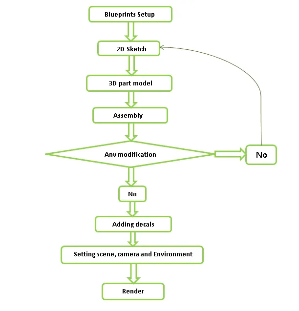
DESCRIPTION:
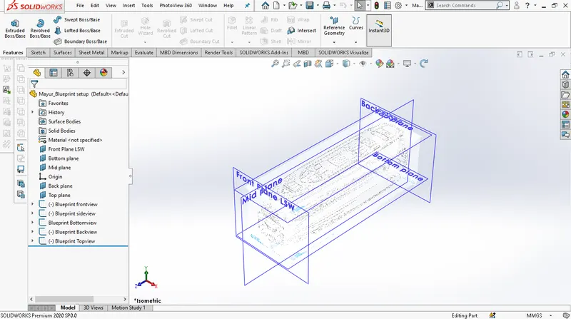
BLUEPRINT SETUP:
Blueprint setup is the unclear vision of final design And views which is placed with proper dimension And orientation. setup is started with creating planes, And then by using sketch mode using sketch picture Command, image with proper dimensions were Added to each plane. Technically, all the parts of yacht Designed using blueprint setup.
DESCRIPTION OF COMMANDS:
Mostly, I have used and got to learn about surface Modelling while designing this yacht. So, here we will Discuss about surface commands. To create complex surfaces it is time consuming process To Model surfaces in solid modelling. Thus, firstly I go through surface modelling commands, using projected Curves, surfaces extrude, trim and various tools of Surface modelling I created external surface. After creating closed surfaces and knitting them together we got option to create solid and like this we convert a surface model into solid model. For this yacht, first we set-up blueprint and then we proceed.
SURFACE COMMANDS :
- Extruded surfaces : Extruded surface is used To extrude sketch contours in one or two Direction to create surface. In this feature Material is added to the sketch and surface Created.
- Swept surfaces : This command is employed To create curved surfaces using profile and path Created in the sketch tool.
- Lofted surfaces : Lofted surfaces is used to Create surface between two edges or Sketches. We can also provide no. of Guide curves to control the path shape.
- Boundary Surfaces : this command lets us to Create surfaces just like what lofted surfaces Allows but it delivers high quality of result than Lofted surfaces.
- Fill Surfaces : fill surfaces is used to fill the gap between edges. it is also similar to lofted surface only difference is, it requires close area while lofted surface can be used with open area also.
- Offset surfaces : when we want to create a Similar surface of selected one but at some Distance then we use this command by Giving required offset distance.
- Ruled surfaces : when we want to create Extra surfaces by selecting the edges of the Surface using various options present like Normal to surface, tangent to surface ,tapered To vector etc. then this command is used.
- Delete Faces : when we want to delete any Surface then this command is used and the Deleted face can be filled also using option like Tangent and fill. If we have any solid body and We want it to convert into surface then we Delete its one face and solid body is converted Into surface as one of its face gets opened.
- Extend surfaces : Extend surface tool can Perform function like extending the one Of the surfaces at intersection.
- Trim surfaces : Trim surface tool is used to Remove Extra surface from the intersection Between two surfaces or surface and plane Or surface and sketch,
- Knit surfaces : there are many small gaps Between two or more surfaces which cannot be Seen by naked eyes which will create problems When we will convert surfaces into solids. So, We knit the surfaces by giving proper tolerance.
- Reference planes : Extra planes are inserted To create some geometry by selecting the Reference like-edges, vertex where the New plane has to be created.
- Projected curve : This curve is combination of Two different curve in different plane but there Both end point coincides.
14. Fillets : this command is used to round the sharp edges by consuming the material there. There are many types of fillets like round fillet, face fillet, etc.
PART DESIGN
HULL:
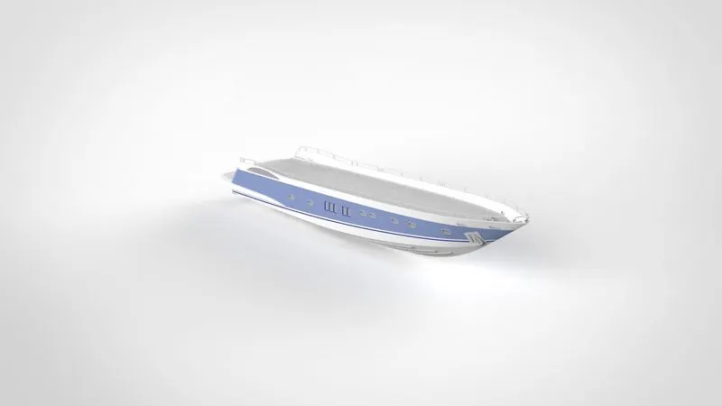
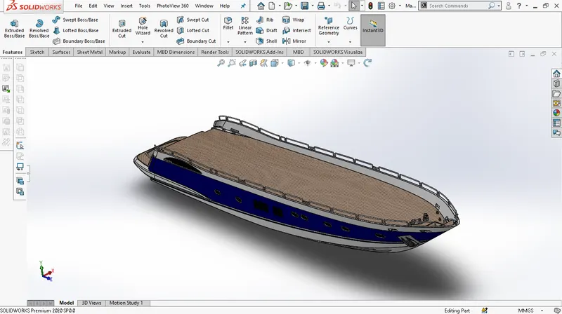
The hull is main structural part of the yacht. Because it’s the hull who bears all the load And create water lift to move the yacht. Thus i took reference of hull surface i.e. deck surface to create Other parts also like seats, superstructure, etc. hull designing started with crating curves similar to blueprints. And then by closing the curves and using surface tools like loft, fill, trim, knit, etc. I created closed surface body. Firstly I designed half hull surface and then convert it into solid body. And then create other bodies on it. For me while Designing hull most difficult part was railings because I had to keep eye on relation every moment. For Improving aesthetics of yacht I applied decals to the Deck, stairs, garage and lower surface. The major Tools while designing the hull were surface loft, Surface trim, surface knit, boss extrude and cut Extrude.
SUPERSTRUCTURE:
Superstructure is an multi body part Which consist of cockpit, table, viper, window. Size of superstructure has great influence on the Speed and mobility. It was designed by taking reference of hull surface i.e. deck surface. While designing I deigned half part and then mirror the part about midplane. Designing the superstructure complex part with solid bodies is difficult and time consuming so firstly i go through surface commands like extrude surface, surface loft ,surface trim, surface fill, ruled surface and i create a external surface of superstructure and by using knit surface creates a solid part. I uses projected curve command mostly and was most efficient for me while designing.
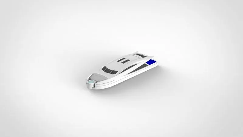
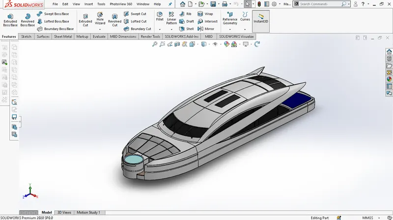
RADAR:
Radar are that device which are employed to Detect other ships and obstacles nearer
to the Ship. It designed using extrude and
fillet feature. One hole is also provided at
the centre for its Rotation.
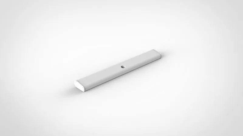
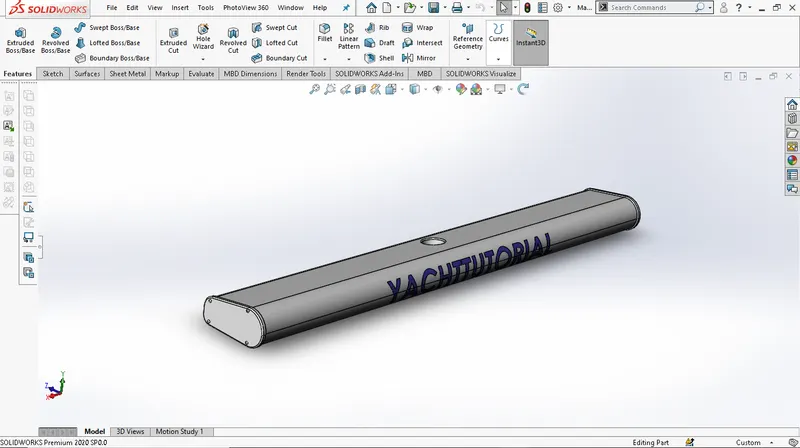
RADAR MAST:
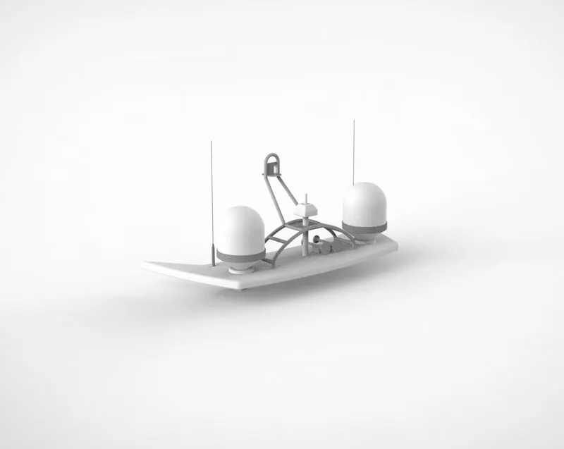
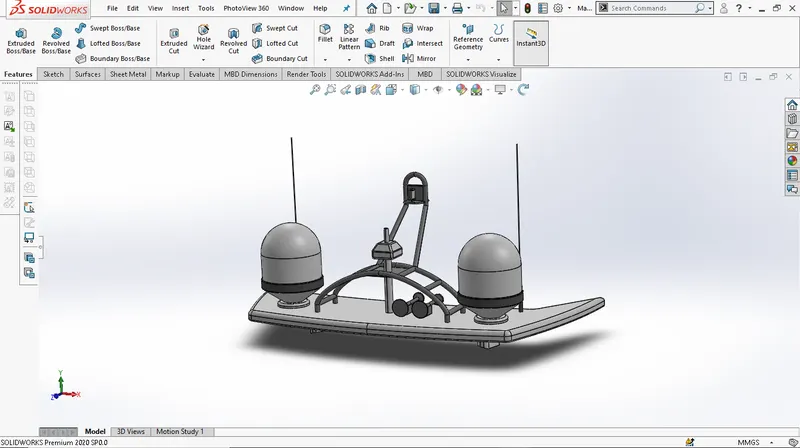
Basically, radar mast is used to hold the radar. Radar mast is an multi body part consisting of Antenna, navigation light, fog horn and radar Scanner. Radar mast was created on superstructure Surface. Commands used while designing radar mast Were boss extrude, revolve, fillets, projected curve, sweep, Shell mirror, etc.
GARAGE DOOR:
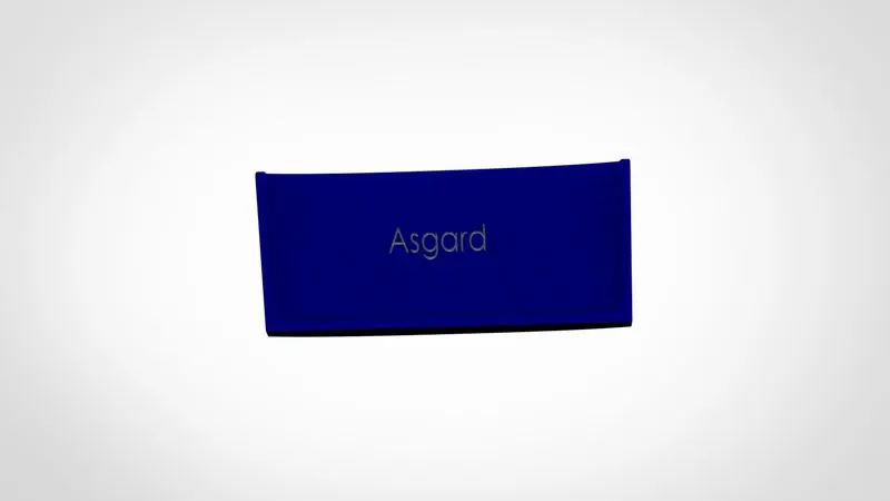
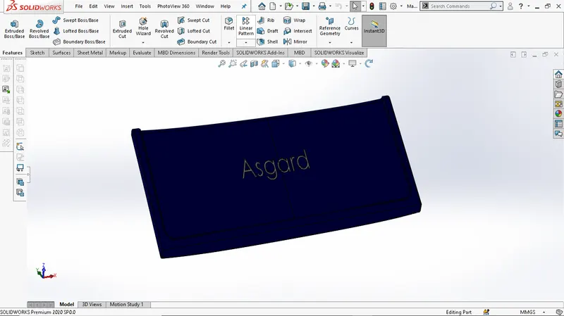
This is simple door which has slited material from Hull part. Holes with the help of cut extrude were Created at upper side for pins, through which garage Door will connect to the hull. As like other parts garage Door also created half and then mirrored about midplane.
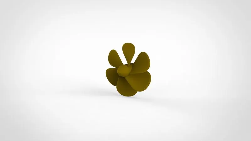
PROPELLER:
Propeller is responsible for the high speed of The yacht. Propeller is equipped with rotating hub and Radiating blades. The blades are specially shaped so that There rotational motion through the fluid causes a Pressure difference. Revolve, loft surfaces, fillets, circular Pattern, are the main features used while designing.

FRONT SEAT:
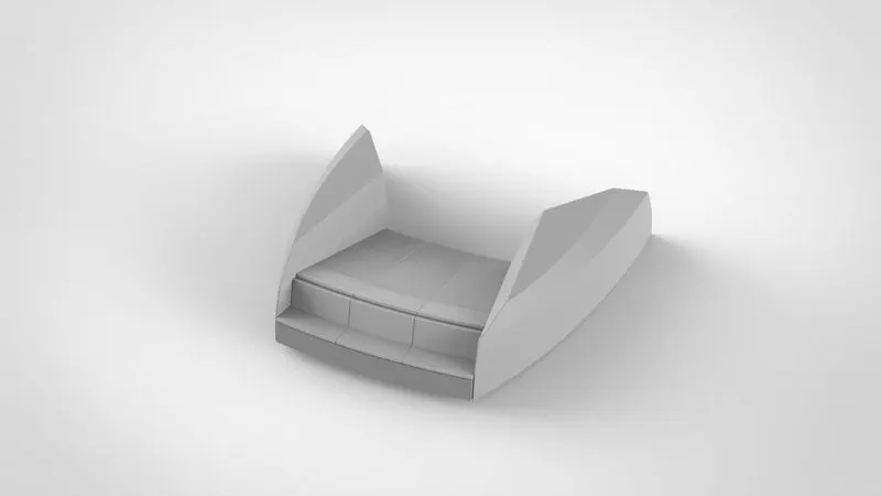
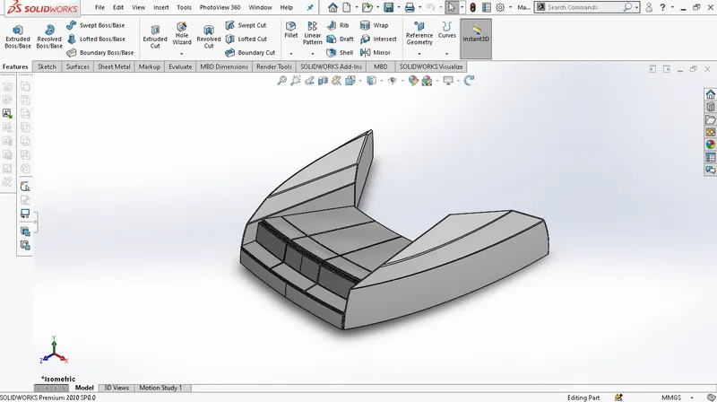
Seats are designed for comfort. These seats are Part of luxury which can be enjoyed with the Co-passengers. Designing of front seat started with creating the Curves with reference to blueprints. All seats Have been designed over hull surface. The major Features used during designing of front seat were Surface loft, surface fill, surface trim, surface knit, Revolve etc. a dome was also created to give Mattress like appearance to the seat.
MIDDLE SEAT:
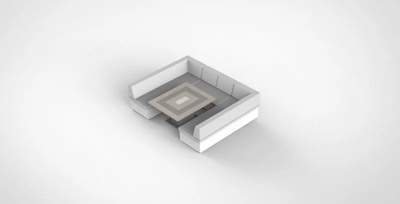
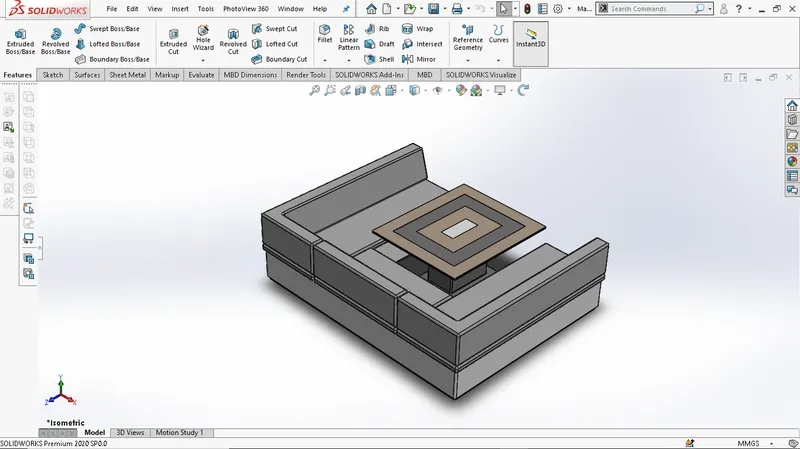
Middle seat is located between superstructure And rear seat. It was created by using taking a references blueprints on hull surface. middle seat is also equipped with dining table. The major command used while designing middle seat are boss extrude, offset surface, fillet, chamfer.
REAR SEAT:
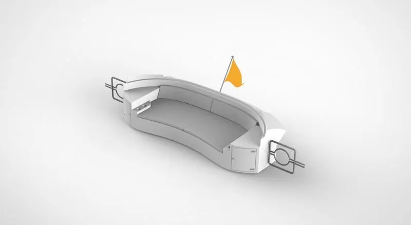
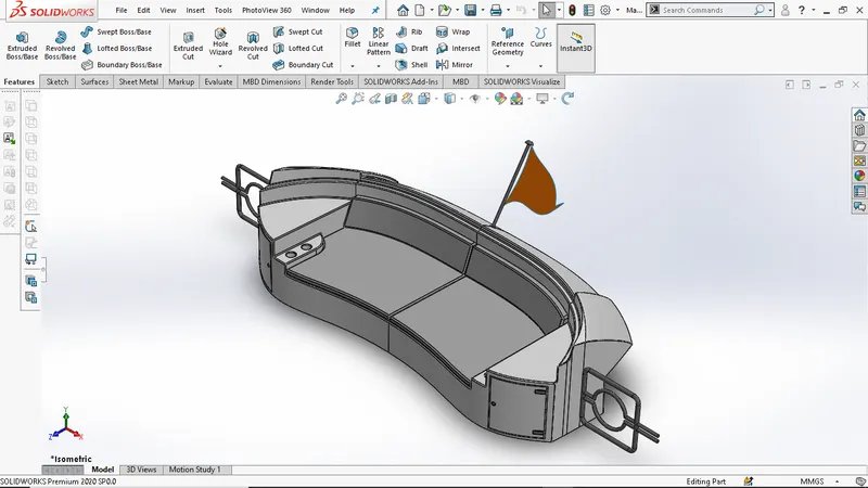
Rear seat was slightly complex among all the seats. While designing I firstly create half surface of rear seat by surface bodies using Surface tools command like sweep, trim, loft and knit. after that I converted it into solid bodies and then mirrored it about midplane. Major surface tools used while designing rear seat Were surface extrude, sweep, loft, fill surface, trim, Extend, Knit, etc.
ASSEMBLY:
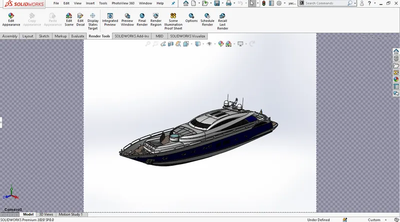
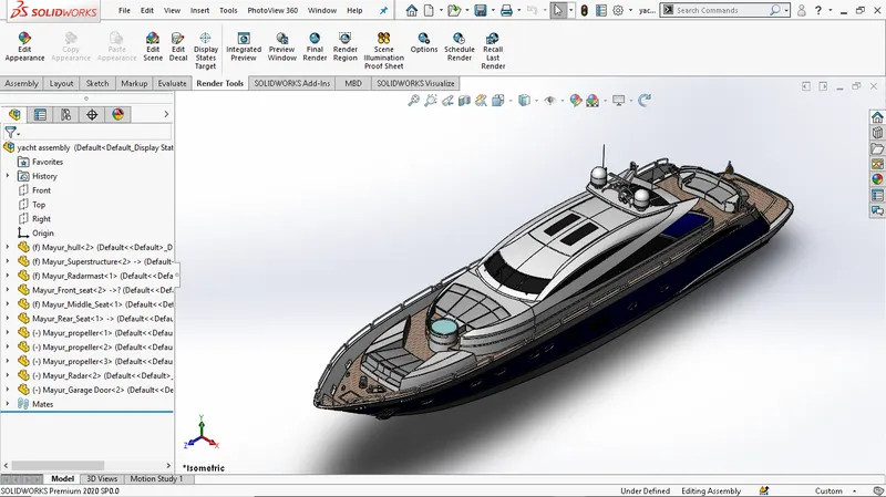
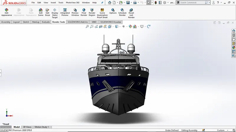
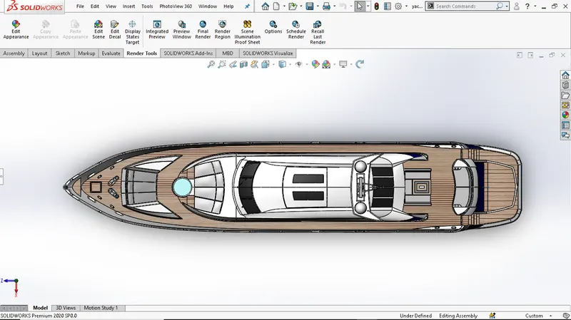
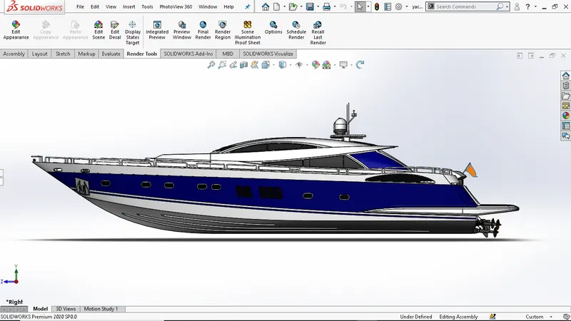
The term assembly is most often Referred toputting components together In an assembly line, but more specially, it refers To creating a complete product that performs an Intended function. In yacht assembly I go through bottom down approach. For assembly of yacht I started with inserting Hull first, It gets fixed automatically. After that I inserted Superstructure, front seat, middle seat it also gets fixed automatically Over the hull, the Reason behind is that while creating superstructure, front seat, I took reference of hull surface. After that I inserted radar mast it also gets fixed automatically over superstructure because while creating radar mast I took reference surface from superstructure. Then I inserted rear seat, radar, garage door propeller, one by one by giving them Coincident, concentric, collinear mate relations.
Camera setup view:
Isometric view:
Front view:
Top view:
Side view:
RENDERING:
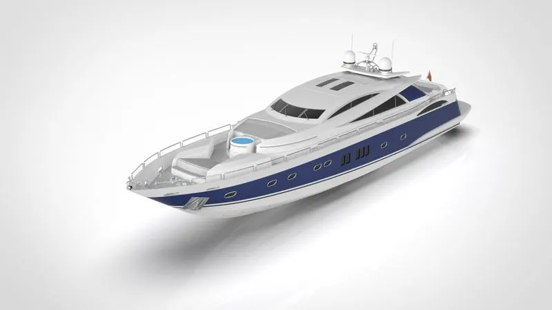
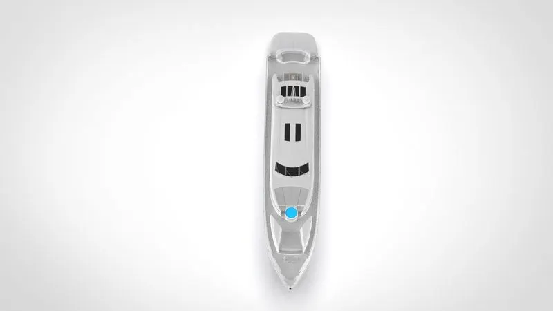
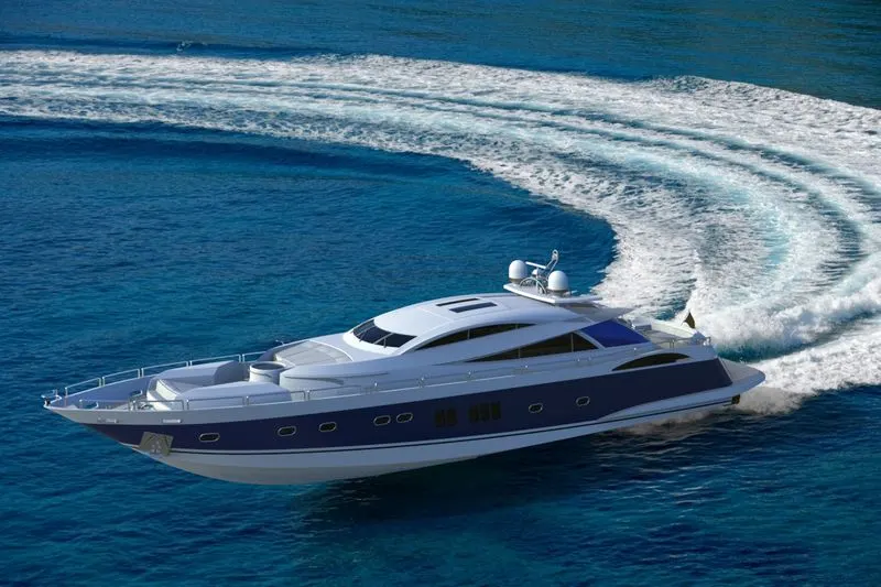
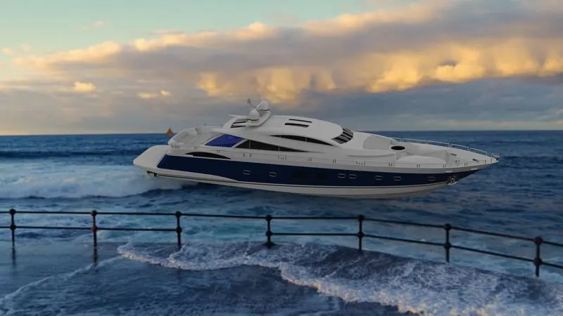
For rendering I used photoview 360, visualize And key shot. I used photoview to add decals and Visualize and key shot software for final rendering. While rendering I added some different backplate images and Environments To match with yacht design. Here are the some Rendered images.
CONCLUSION:
In this project I learned how to model sunseeker Predator yacht in solidworks and learn how to Design complex part using surface modelling commands. At the end of project I gain hands-on experience in Modelling a complex design. And i learned Solidworks Software in industrial manner. this project helps me To enhance my designing skills and help me to become Industry ready for the role of design engineer.