Advanced Sheet Metal Design Using NX Cad Challenge_2_Box Assembly
TITLE: Sheet Metal Box Assembly Design using NX CAD.
OBJECTIVE:
To Design sheet metal Box Assembly Using Siemens NX cad software to get hands on Experience on NX.
INTRODUCTION:
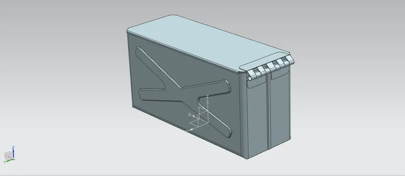
Sheet metal is the most versatile material in the Manufacturing industries. And its uses expand across many different industries including Aerosace, transportation, manufacturing, industrial furniture, machinery etc. in this challenge I have created the Box Assembly using various basic feature of NX cad like tab, flanges, bend, dimple, lead, mirror, unbend, rebend etc. the Box assembly consist of different bodies like the Box, the lid and the hinges.
METHODOLOGY:
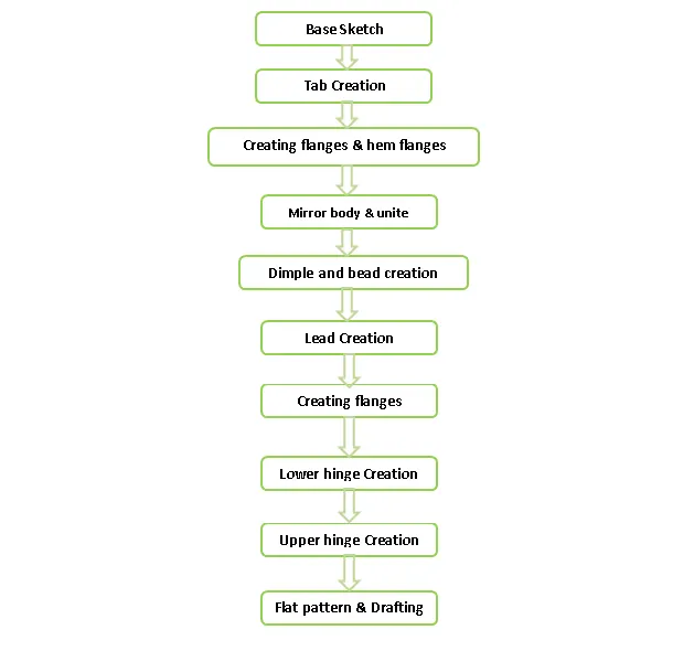
Box assembly is designed by keeping industrial procedure in mind to follow the design intent. The design methodology used for this project can be summarized as depicted in the flow chart.
DISCRIPTION:
the designing methodology and all the features used while designing box assembly is briefly described below. Some of the features were repeatedly used at perticular instances while designing.
SKETCH:
Sketches are the main basic foundation of design model. With sketches firstly I perform tab operation after that I created other features with sketches like Dimple, bead, hole etc.
TAB:
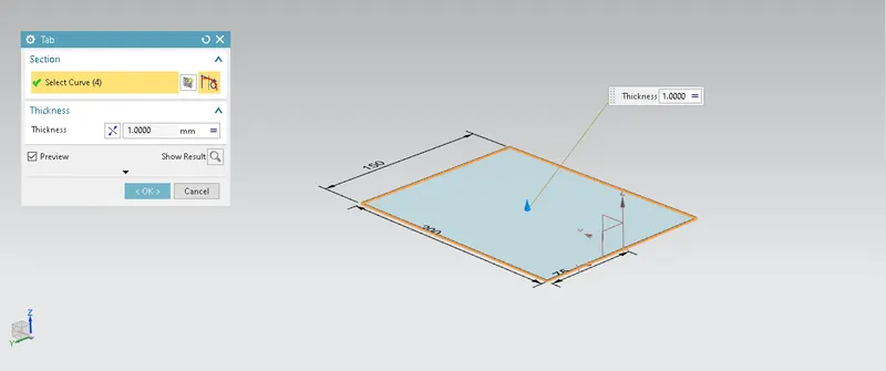
Tab is the main parent feature while designing in NX. after tab, other features are perform on it. Firstly I creates a rectangular sketch on XY plane having dimmensins of 150*200mm then creates the tab feature.
FLANGE:
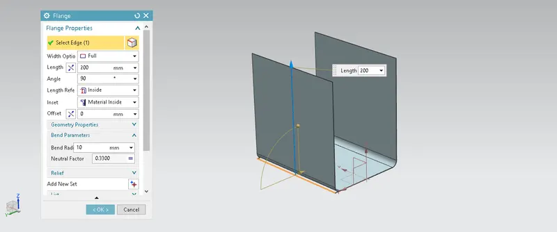
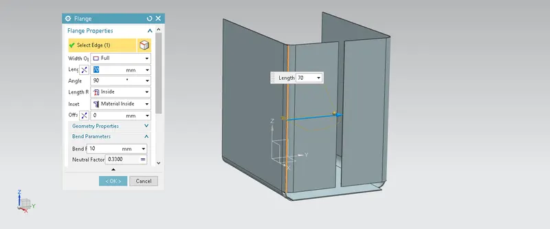
Flange is used to add material at any angle and length. After tab I creates the flanges normal to XY plane of dimmensions 200mm length and bend radius 10mm by selecting the edge of tab and then another two flanges created normal to the XZ plane of length 70mm.
CLOSED CORNER:
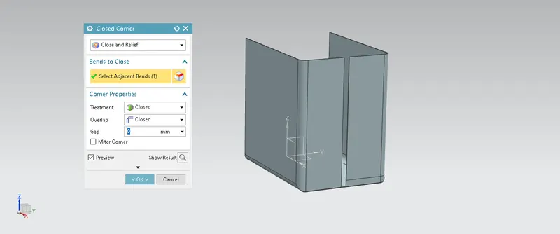
Closed corner feature is used to closed the open corner where two adjacent flanges meet by adding material. In this I closed open corner twice between two adjacent flanges.
FLANGE FOR FASTENING:
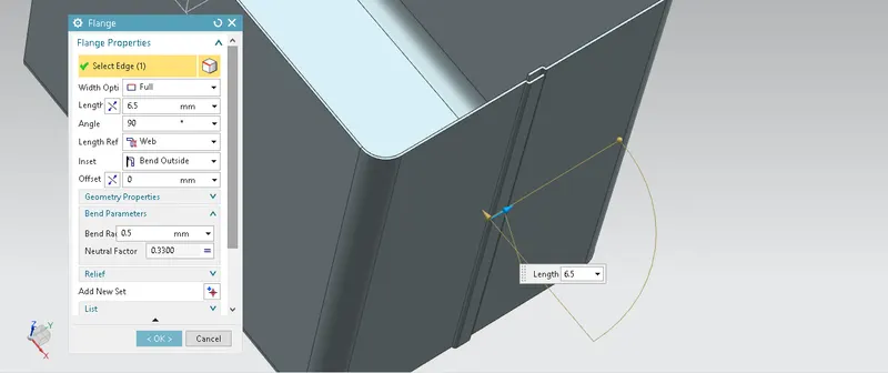
For connecting and fastening two flanges first I created flanges of length 0.02mm and radius of 0mm on both flanges then created another flanges of length 6.5mm and radious of 0.5mm on previously created flanges with outside bend.
HEM FLANGE:
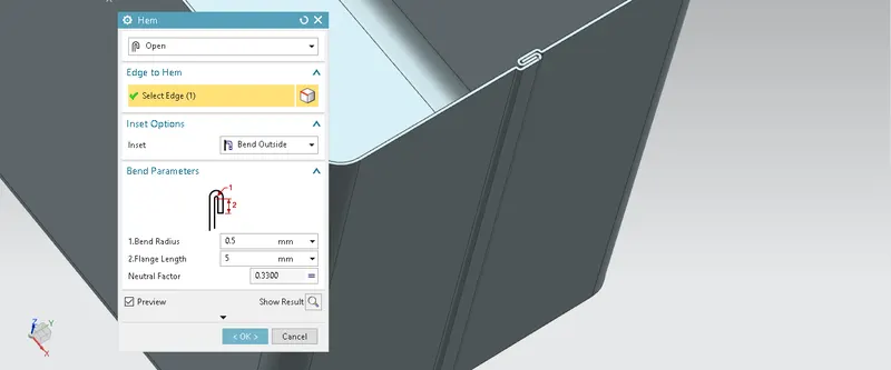
Open hem flange operation is done at the two supporting flanges to joint the sheet metal rigidly. This gives stiffness to the assembly as well as asthetic look.
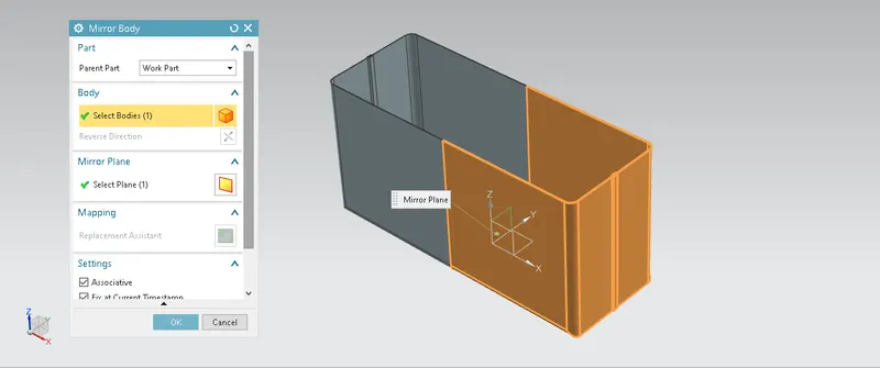
MIRROR BODY:
After hemming operation, one half of the box assembly is ready. To get the another half we have to perform mirror body operation so that the same half is reflected without any error. This operation is done by selecting the half body and YZ plane.
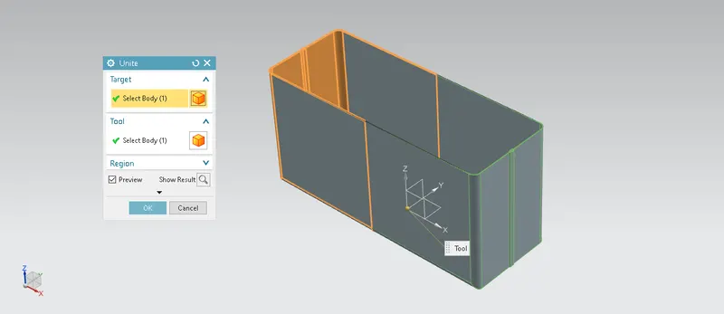
UNITE:
Unite feature is used to combine two different bodies which are in contact to make it as a single body. I used this command after mirror body.
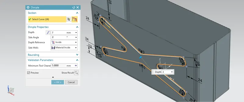
DIMPLE:
Dimple feature is created at the side wall of box assembly. Dimple feature is used to lift the area of model inside the sketch. For this I firstly created a sktech of appropriate dimmensions and then creates a dimple feature. after that mirror the feature about XZ plane. Another rectangular dimple was created at the bottom side of box. Dimple is used to strenghthen the sheet metal part.
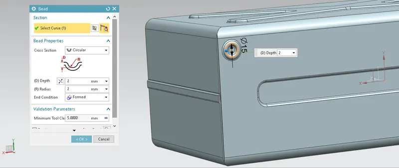
BEADS:
Bead is similar to the dimple only difference is that in dimple we lift sketch area while in bead we lift sketch contour. Beads are added in sheet metal in order to increase the stiffness and strengthen the component. In this I firstly creates the sketch of circle having diameter of 15mm, then creates a bead. After that other beads are created by pattern feature command by selecting XZ and YZ Planes.
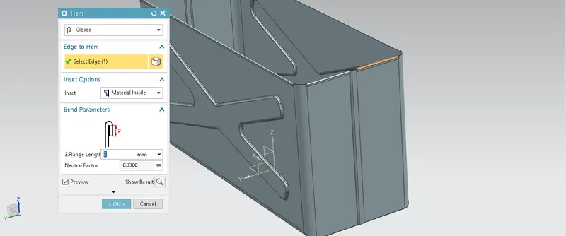
HEM FLANGE:
In this step closed hem flange I used to create rounded edge for handling and safety purpose.
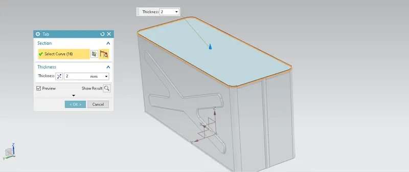
LID CREATION:
For lid creation, firstly i have created a datum plane by taking reference of XY plane then offset it at a length 203mm. then on this plane sketch was created by taking reference of edges from top view of box design. Then base tab was created having a depth of 2mm.
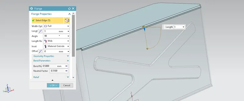
CLOSING FLANGES:
After creating lead there is a gap between box and lid which can be closed by creating web flange of length 3mm on four sides of box.
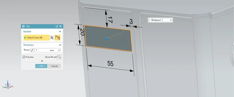
TAB FOR HINGE:
Rectangular tab of appropriate dimmension was created on the face of box or on YZ plane.
BREAK CORNER:
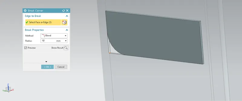
Break corner feature is used to smoothen the corner by giving chamfer or fillet to it. Break corner is used to prevent stress concentration and fracture breaking while manufactring. In this I had given a fillet of 10mm to one of the corner.
FLANGES:
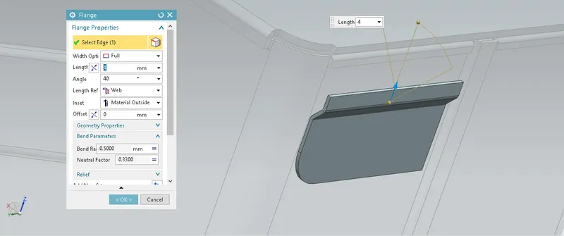
For obtaining required hinge two adjacent flanges are created at an angle of 40 degree and length 4mm.
HEM FLANGE:
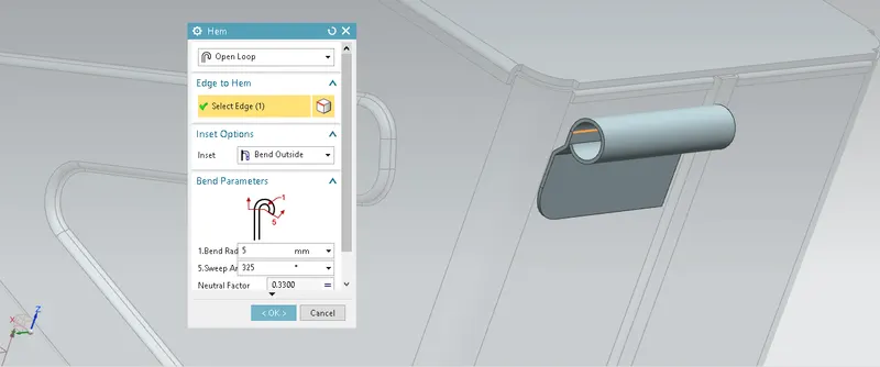
Open loop type hem flange was created on the edge of newly created flange by giving a radius of 5mm and sweep angle of 325deg.
UNBEND:
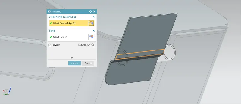
Unbend is the most likely used feature in NX. In industry while manufacturing we have to first unbend the sheet metal then we have to perform certain operation on it for easy and accurate manufacturing. Thus, similar activity we followed in the simens NX. In this box assembly design I used this command twice for further operation.
NORMAL CUTOUT:
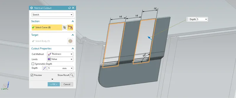
Normal cutout feature is used to remove material. Firstly I creates a sketch on a face of previous unbend sheet of appropriate dimmensions and then remove the material perpendicular to the face. Then it automatically forms a hinge part.
REBEND:
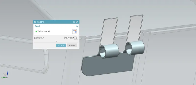
Rebend is perform to restore previously created bend on unbended part without disturbing previous bends. While performing rebend we have to keep eye on selecting bends in order they unbended. In this box design I used this feature thrice.
MIRROR FEATURE:
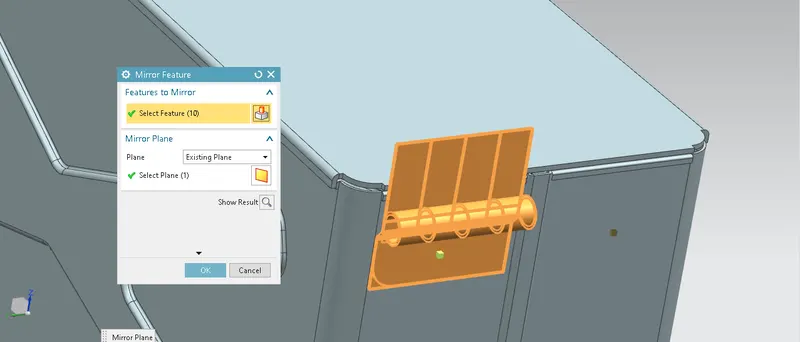
After creating tab and hinge on half part it is then reflected on another side without any error by mirroring it about YZ plane.
TAB FOR UPPER HINGE:
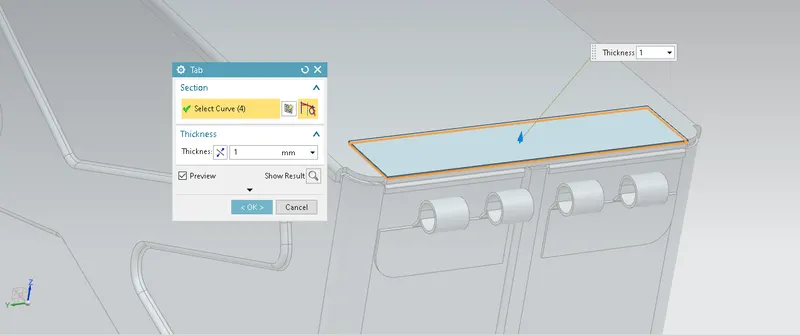
Rectangular Tab is created on upper side of box assembly. it act as a base for upper hinge.
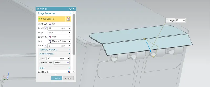
FLANGES:
Similar, as we created bottom hinge, flanges was added. on the top hinge also flange of 45 degree and 13mm was added.
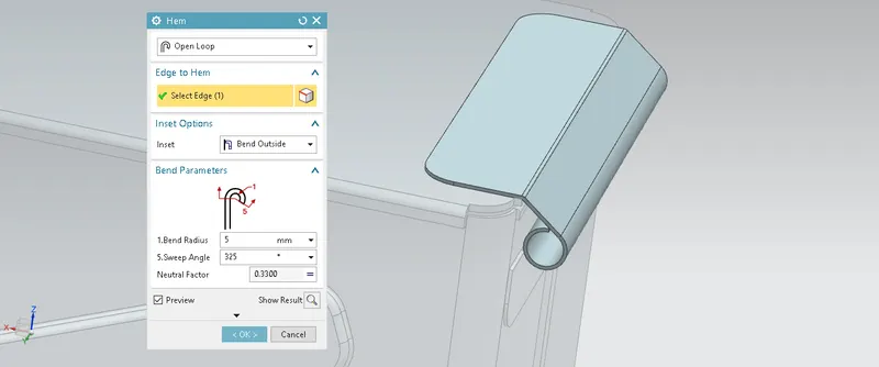
HEM FLANGE:
As we created an open hem flange on bottom side similar open flange of 5mm radius and 325 sweep angle was created on top side.
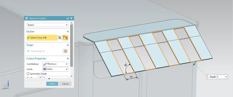
NORMAL CUTOUT:
Firstly, I unbended the earlier created hem flange then By doing sketch on the face of the previously created hem flange we can remove material perpendicular to the sketch to obtain desired hinge barrel.
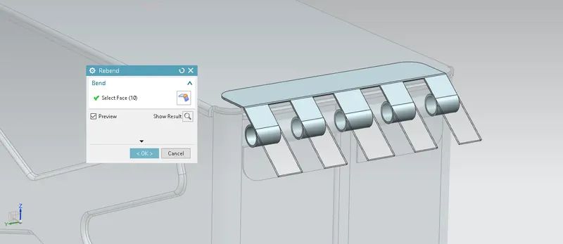
REBEND:
by doing the rebend, hinge barrel of box assembly part was created and thus design of sheet metal box assembly completed.
FLAT PATTERN:
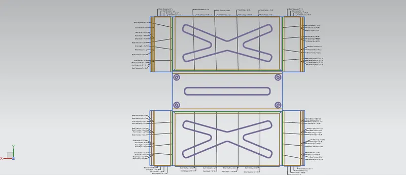
Flat pattern is the representation of the entire sheet metal component in the 2D form with all the bends, cutouts, holes, and additional features in the form of lines or edges. The flat pattern ensures the ability to cut the sheet metal out of the raw sheet metal plate. It removes the possible errors such as interface or collision within the same component.
DRAFTING:
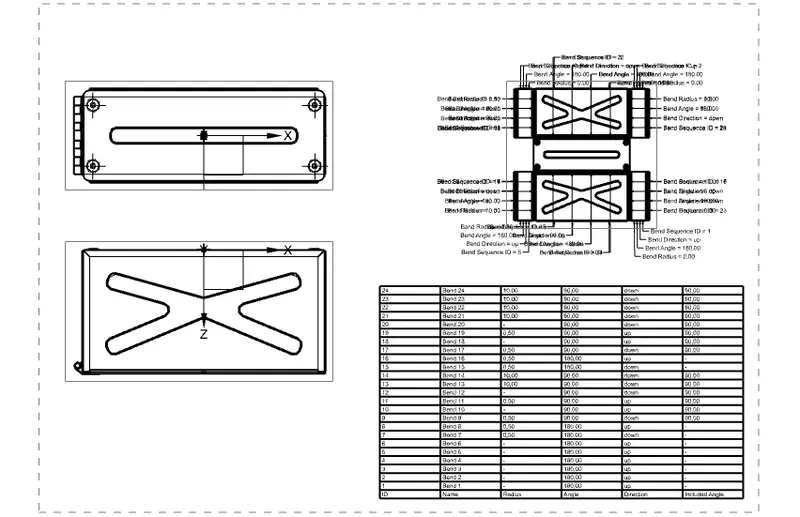
After the modelling, the manufacturing requirement of the component a technical 2D drawing of the component with accurate dimensions or scales denoted. For achieving this we are using the command draft.
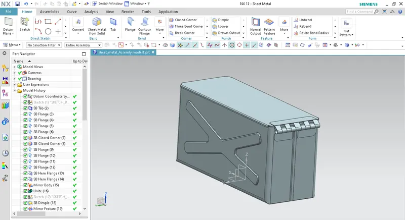
Different Views of Box Assembly design:
Iso View:
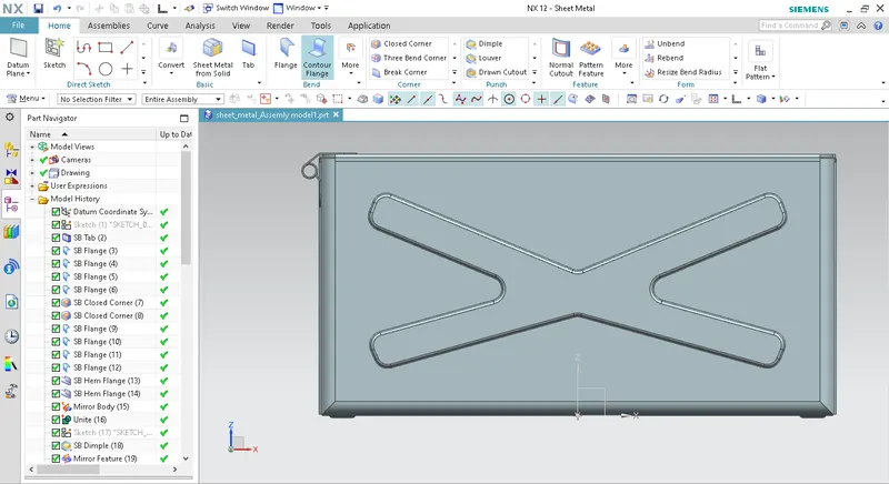
Front View:
Top View:
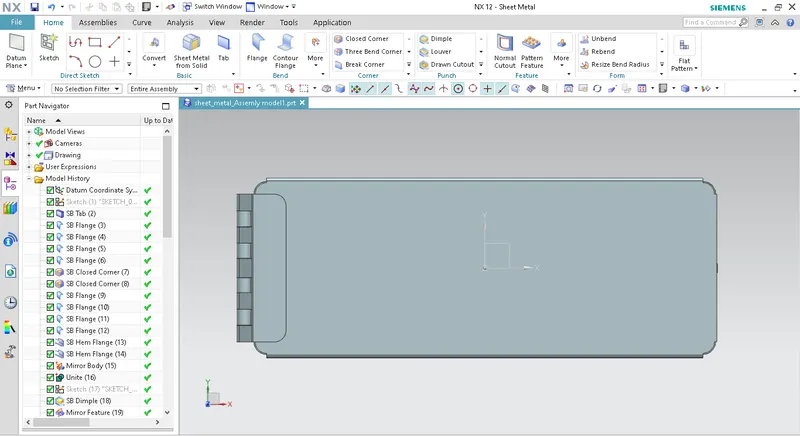
Right View:
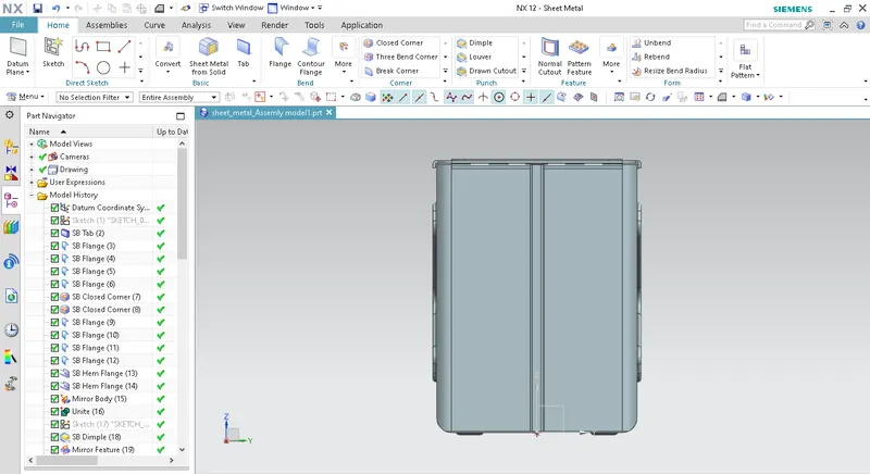
CONCLUSON:
- Succefuly learn to design sheet metal box assembly in industrial manner.
- Improves sheet metal designing skills.