Advanced Sheet Metal Design Using NX Cad Challenge_1_Casing Design
TITLE: Sheet Metal Casing Design
Using Siemens NX.
OBJECTIVE:
- Comfortable with using NX CAD
Software.
- Learn to design a sheet metal casing
in industrial manner.
INTRODUCTION:
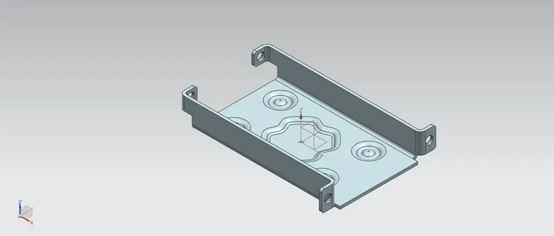
Likewise other CAD software Nx also provides the same purpose of designing or modeling of a part, assembling, drafting etc. Nx adapts user friendly environment furthermore, it also delivers innovative technologies for maximum productivity and creativity from the basic concept of to the final product. Sheet metal parts are widely used in machinery, automobiles, aerospace, enclosure, brackets. In this project I used NX CAD to design sheet metal casing.
METHODOLOGY:
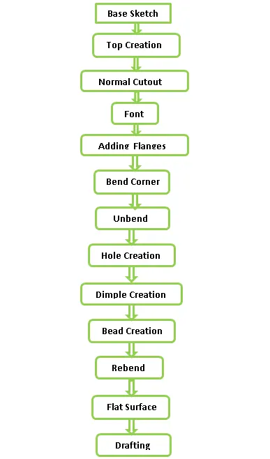
Simple methodology is followed during sheet metal casing design. While designing i have to keep eye on dimple Feature direction and rebending feature. The design methodology used for this project is as followed.
DISCRIPTION:
Sketch:
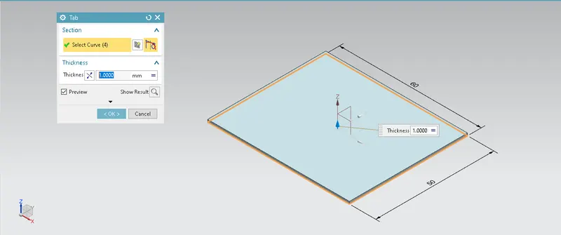
For creating any sheet metal design we have to create sketch firstly. So, I started with creating a base rectangle on XY plane then goes for tab feature while designing, the default thickness, bend radius, relief depth and relief width value are set to 1mm. other than tab , various sketches are also created on different planes and faces for further designing.
TAB:
Tab is the base or parent feature of the sheet metal casing design. Other features are based on tab. So, for creating tab I create a sketch of reactangle having a dimmesins of 50*60 then creates a tab having a depth of 1mm.
NORMAL CUTOUT:
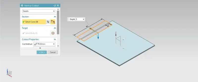
This command is used to cut the material by projecting the sketch onto the model and then cutting perpendicular to the faces intersected by the projection.
BEND:
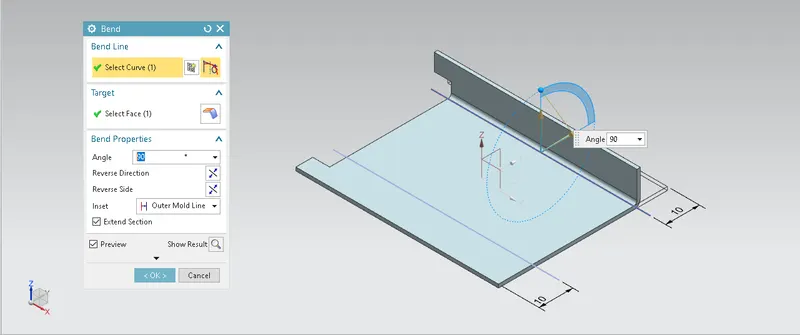
Bend feature is used to bend the sheet metal component to any angle and length. While creating bend I firstly draw a sketch of two symmetric lines along x-axis and then by selecting lines goes for bend at 90 degree angle.
FLANGE:
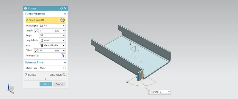
flange is used to add extra material to the existing edge at any angle and of any size. If we select internal edge then flage goes inside. If select external edge flange goes outside. In casing design I added four flange on different edges.
BREAK CORNER:
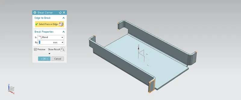
This command is used to round or chamfer the sharp edges of the sheet metal parts. This action helps to prevent fracture braking while manufacturing and comfortable to handle break corner parts.
UNBEND:
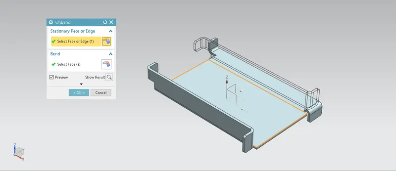
Unbend feature is the most important command In sheet metal design. Holes, dimple,beads etc features are not directly generated on bending part so to generate those command on bend we have to first unbend it and then bend it. Also in industry we have to mark all the marking and sketch on flat sheet metal before it went to production. I used this feature by selecting tab is stationary and then selecte the bend portions.
HOLE:
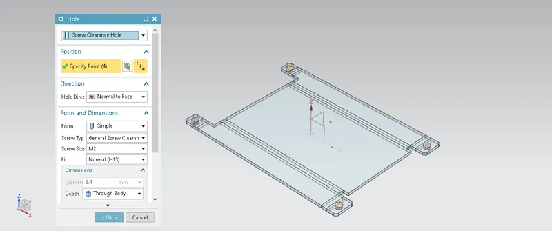
Hole feature is used to generate hole with definite parameter on sheet metal in NX. In this I used simple screw clearance type hole. Firstly I draw four points with reference to x-axis on unbended flange and then creates a holes.
DIMPLE:
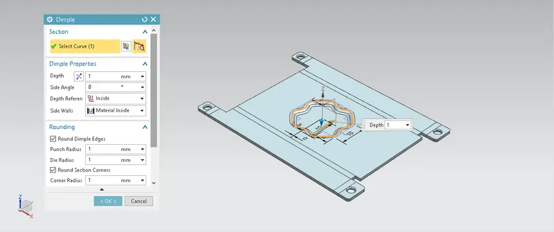
Dimple command is used to strengthen the sheet metal part. This command lifts the area of sheet metal under the sketch. For creating dimple I firstly draw a sketch using line command then I used studio spline option to give smooth curve to the sketch aftter that I go to the move curve then I moved the sketch in 45 degrees angle. Then by selecting sketch I creates a dimple command. While creating dimple we have to keep eye on direction of dimple.
BEADS:
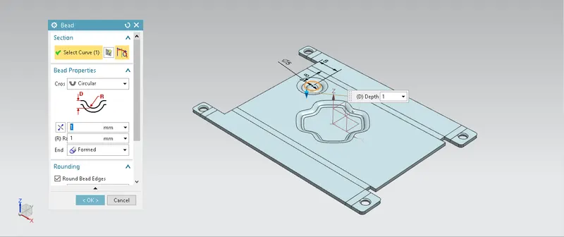
Bead is also used to strenghthen the sheet metal. Bead is similar to dimple only diffrence is that in bead we lift the countour while in dimple we lift the area. For creating lift I draw a circle and by selecting circle perfom a single bead. Then by using pattern feature command creates an other beads.
REBEND:
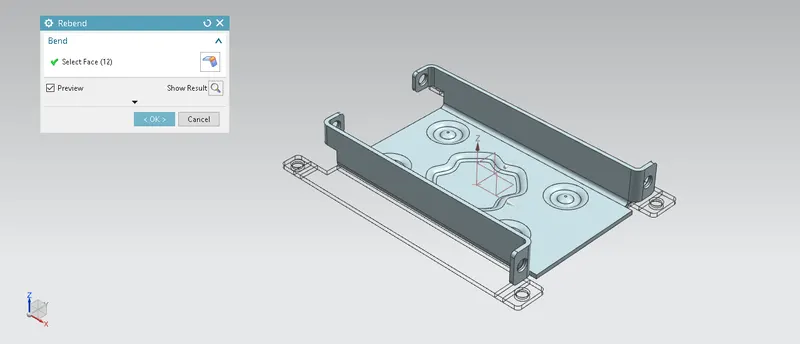
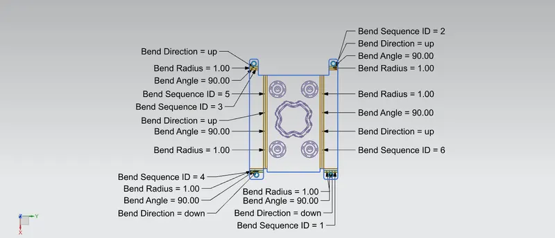
Rebend feature is used to bend the sheet metal as it was in initial condition without changing the features created after unbend on sheet metal part. While creating rebend we have to select bends sequencely as we selected in unbend feature.
FLAT PATTERN:
Flat pattern command is used to convert 3D model into 2D form and gives information of all the features we have used.
DRAFTING:
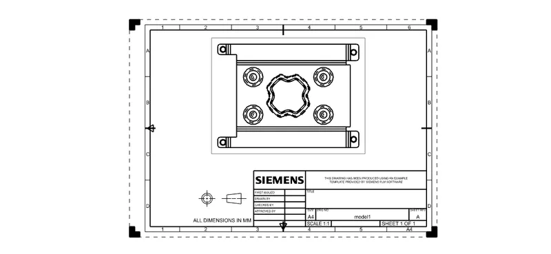
After completing 3D model design is goes for futher manufacturing process for easy interpretation we have to convert it into 2D and it is done by drafting.
Different View of Casing
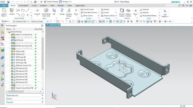
Isometric View:
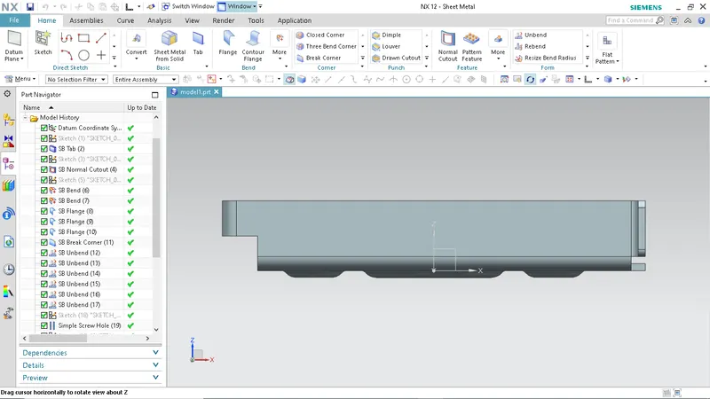
Front View:
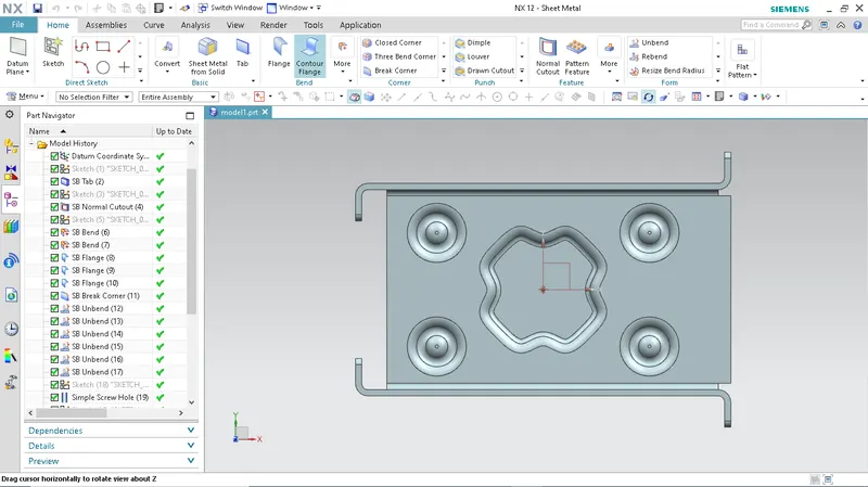
Top View:
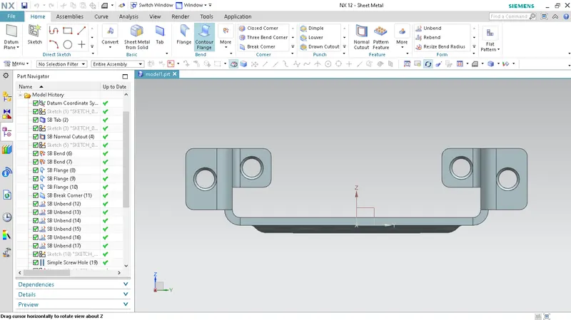
Side View:
CONCLUSION:
- Learned how to design sheet metal casing using siemens NX software.
- Become comfortable and user friendly on Siemens NX, while designing sheet metal casing.