Week 9 - Project - Master Section Development
Hi colleagues,
good day,I am sending you procedure for B PILLAR design.
At first I have opened the part to see input and a structure.There are CLASS A SURFACE and Mastersections with a pair Axis Systems.
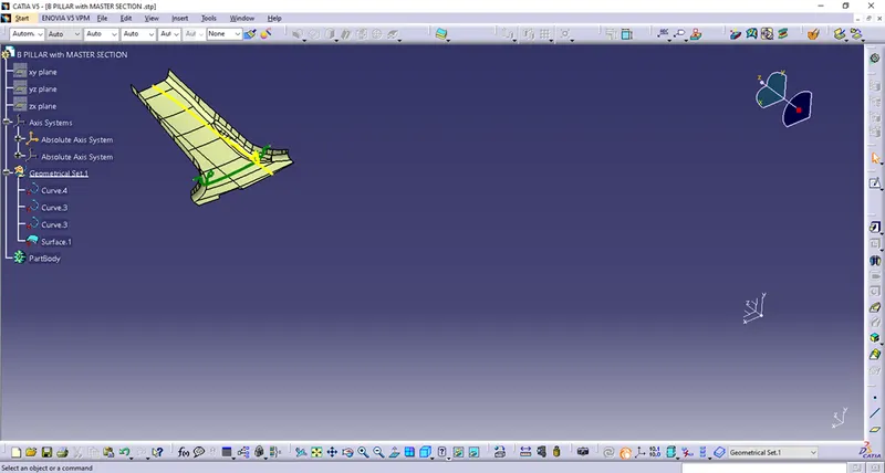
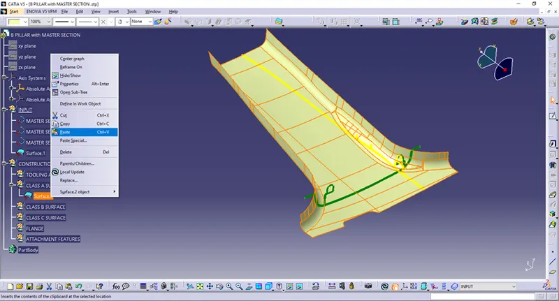
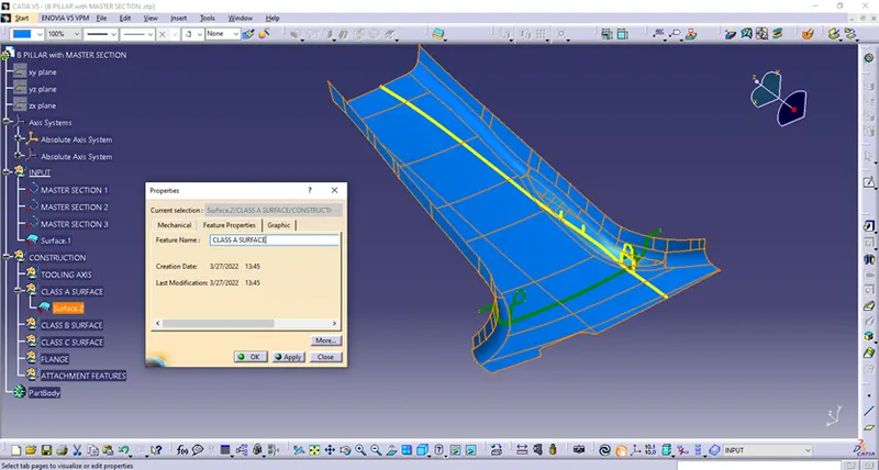
I have renamed that Geometrical Set as a INPUT and inserted new one with name CONSTRUCTION.Under CONSTRUCTION I have inserted Geometrical Sets TOOLING AXIS,CLASS A SURFACE (there I have copied given surface from INPUT),CLASS B SURFACE,CLASS C SURFACE and as requested in Challenge FLANGE and ATTACHMENT FEATURES.
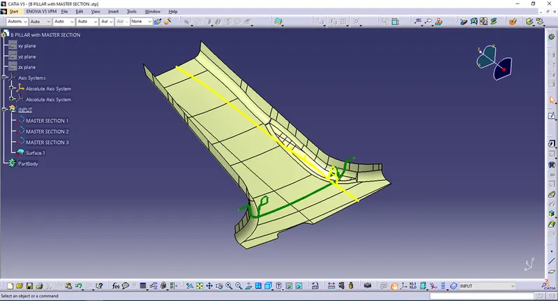
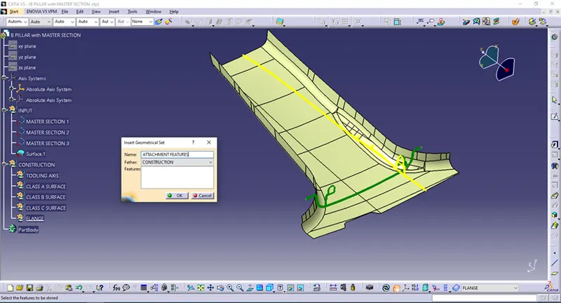
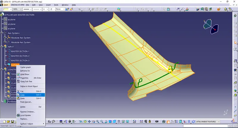
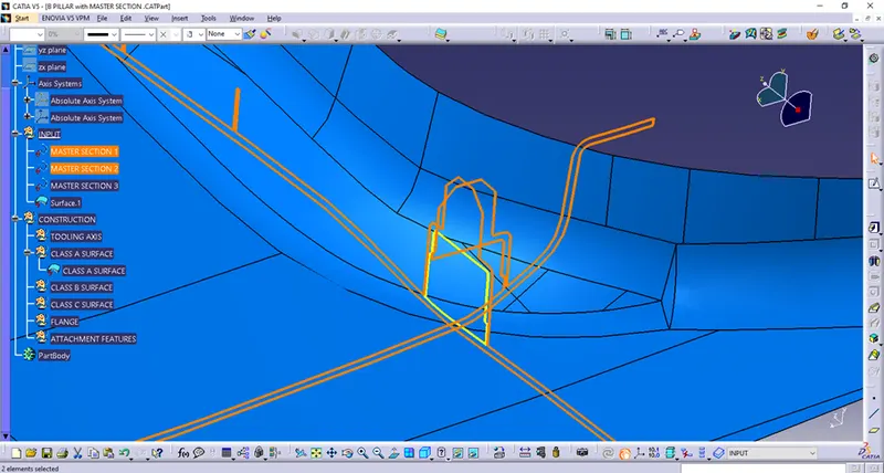
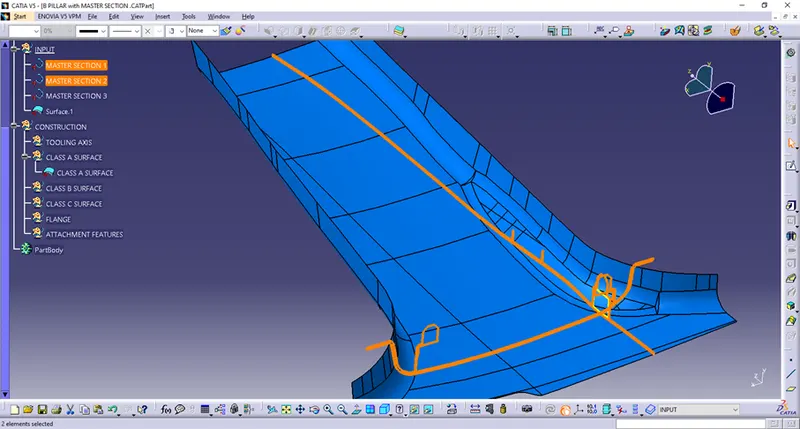
From mastersections it can be seen that we have 4 way locators with doghouses and ribs along the B PILLAR.
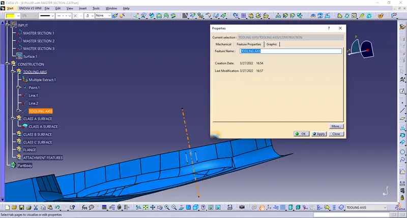
I have to deal with TOOLING AXIS first.I am going to extract lines from 4 way locator.If it is 4 way locator as I presume,in the middle of extracted lines I will define a bisecting line to be my TOOLING AXIS.
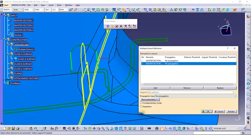
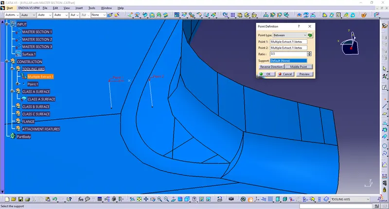
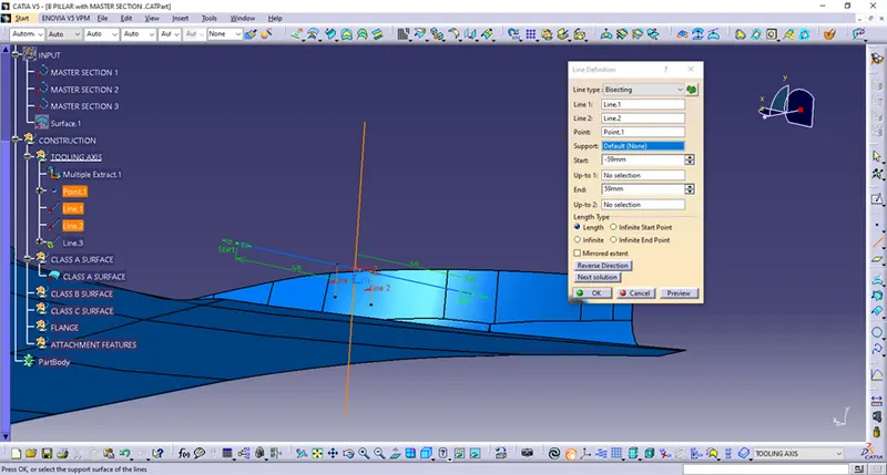
That will be my TOOLING AXIS.
I have to construct CLASS B SURFACE,but as it can be seen from given INPUT – Master Sections are going over and behind given INPUT surface,they are having some flanges also.
That means I should improve INPUT surface to get my CLASS A SURFACE (with flanges).So,I will first construct CLASS A SURFACE (with flanges as given in Master Sections).
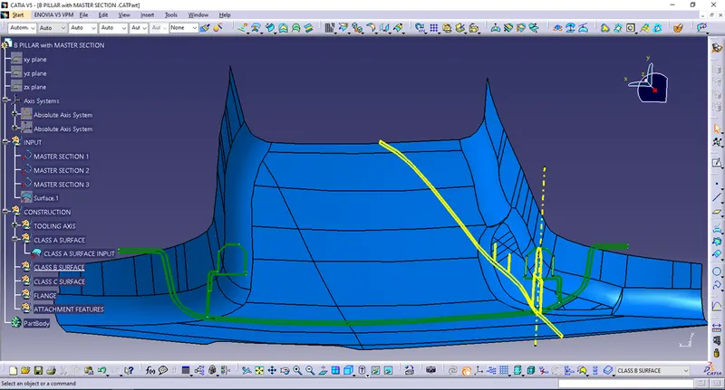

At first I wanted to investigate quality of INPUT surface – I have pointed in the middle of the surface mouse pointer and with options boundary and extract I got results as bellow.
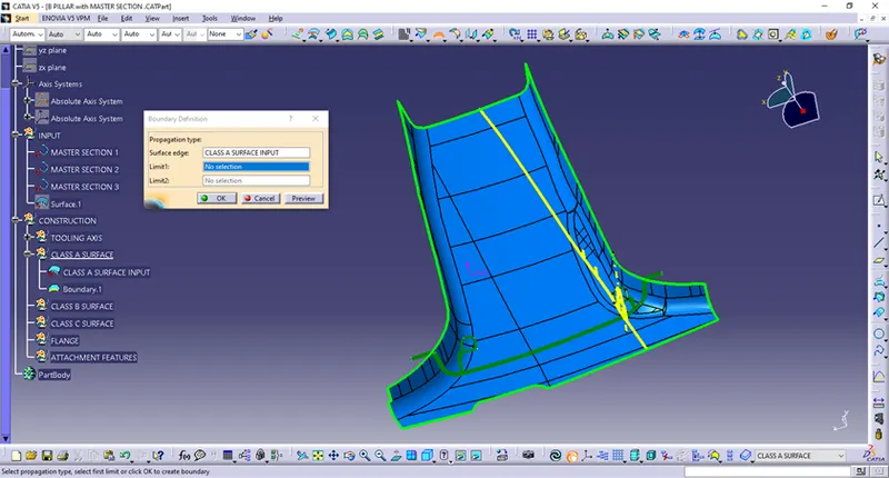
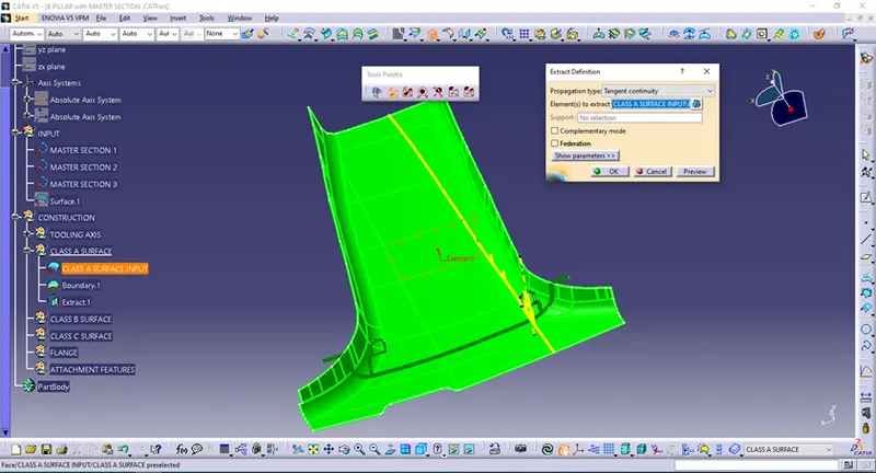
It looks fine and without interruptions or breaks.
I will insert a plane in the TOOL AXIS point and through Master Sections line and do intersect with that plane and extract.
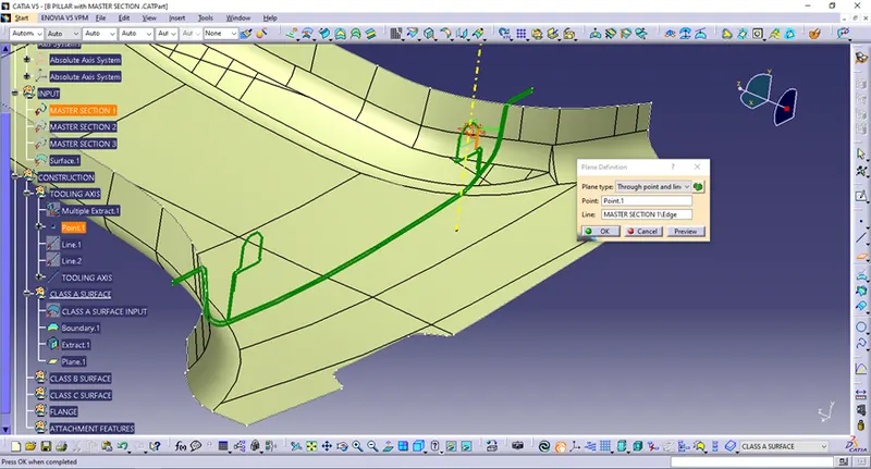
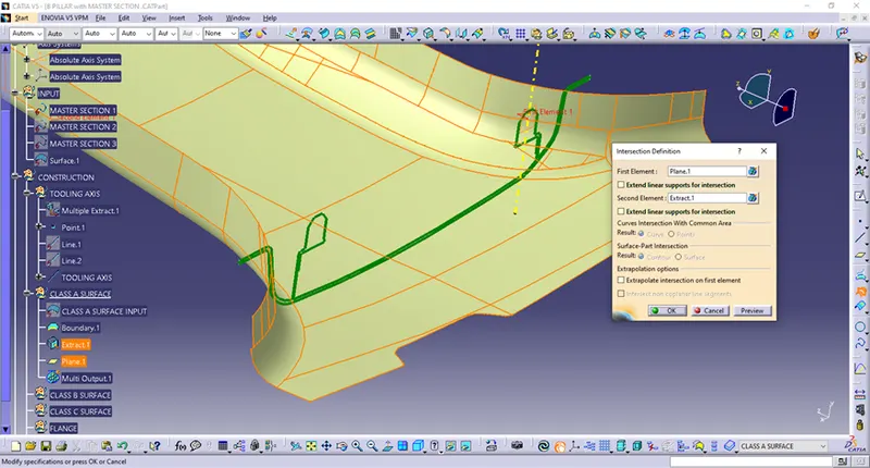
I have extracted lines from mastersections.
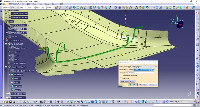
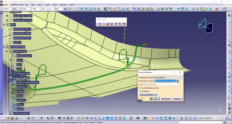
On the extracted lines base I have drawn following lines for sweeps.
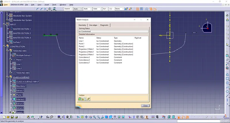
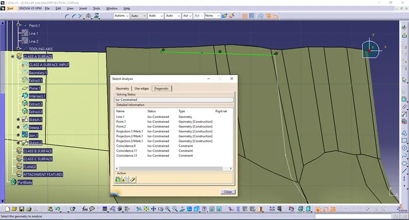
There is a little problem,gap in the surface,there I have spline construct and then fill it.
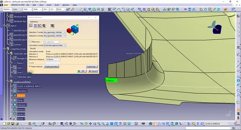
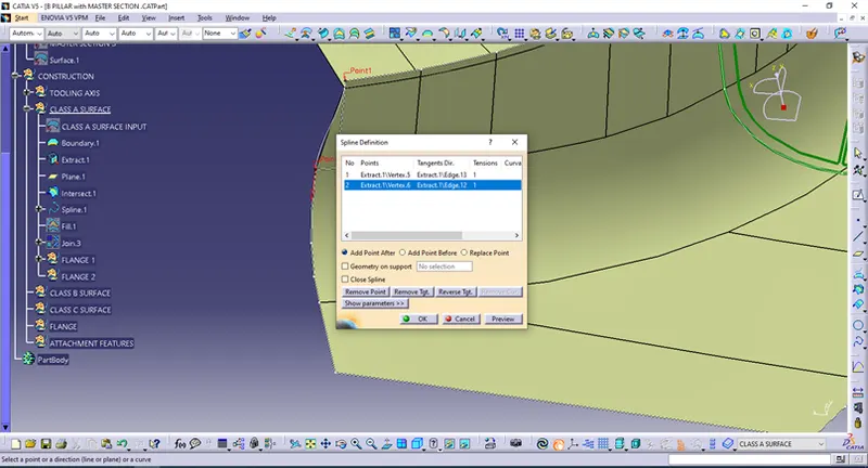
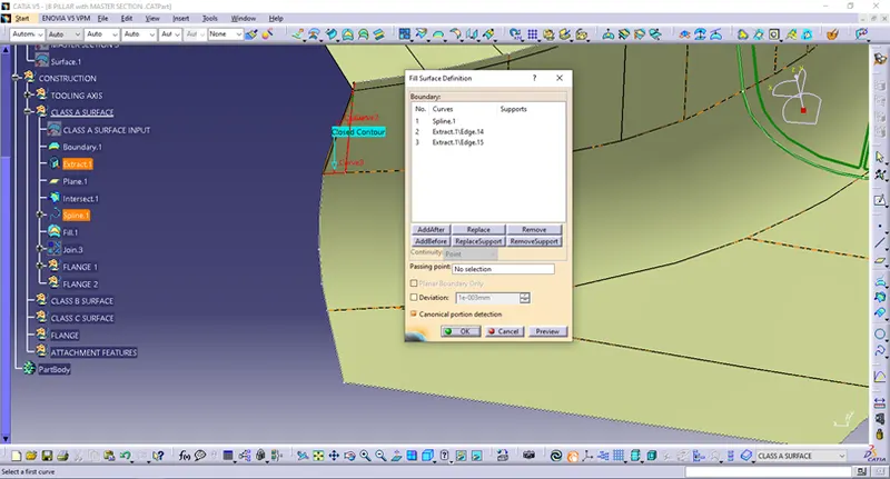
And then I have joined surfaces.
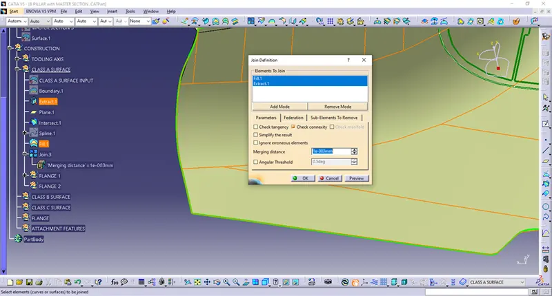
Now I have to construct flanges.
Intersection line is a little bit longer (it is because of fillet of mastersection) but there is a little difference in angle between mastersection line and extracted line.I will correct it - extract second line also and join those lines.
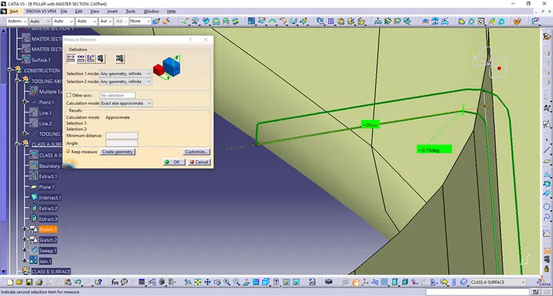
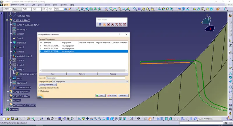
I have replaced simple with multiple extract.
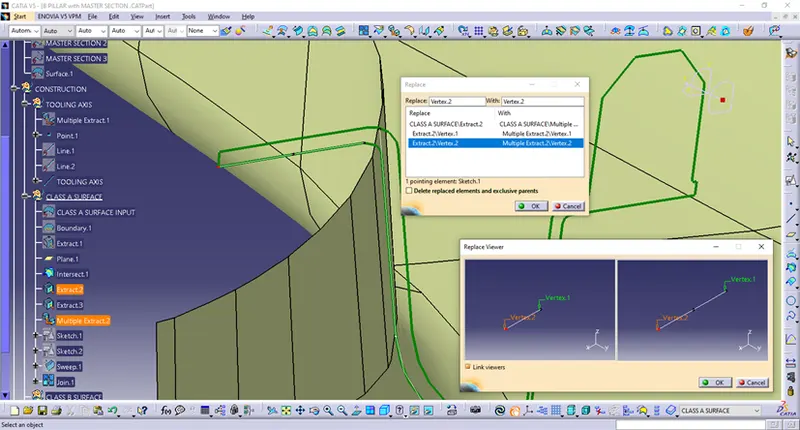
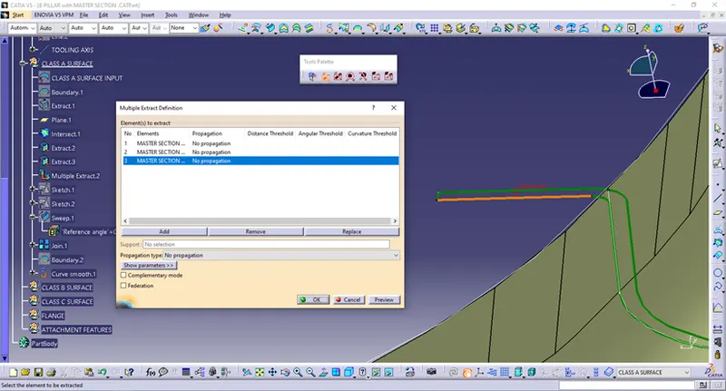
I have done boundary (then curve smooth) and sweep.
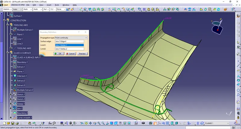
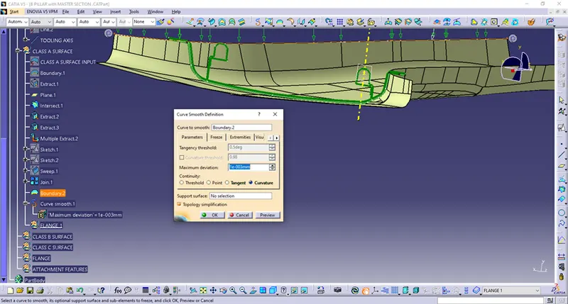
I have inserted new Geometrical Set FLANGE 1 where I will move following features.
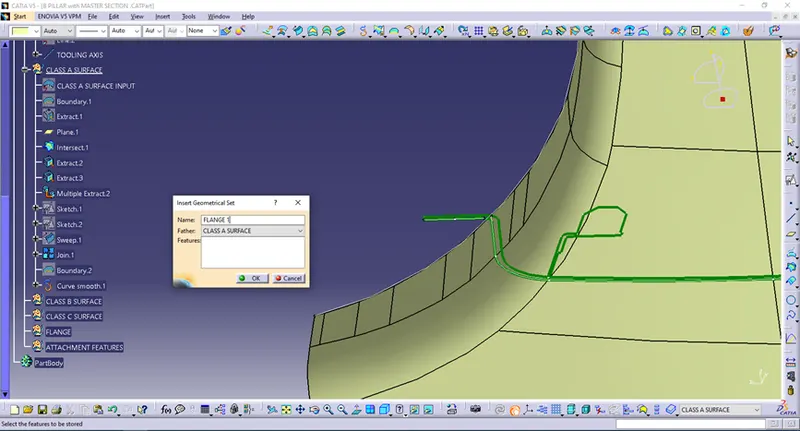
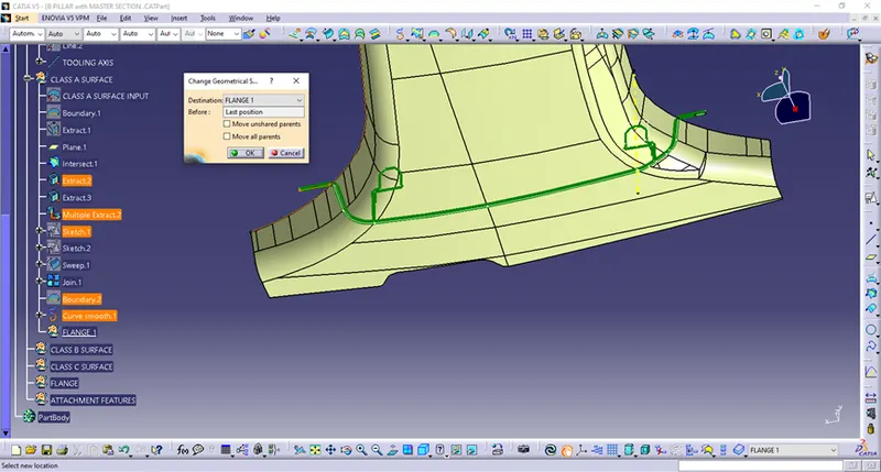
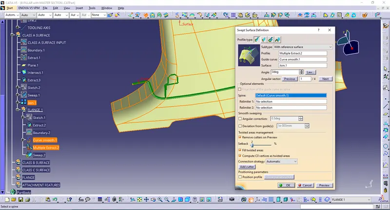
I have make a boundaries and smooth curve and afterwards sweep.
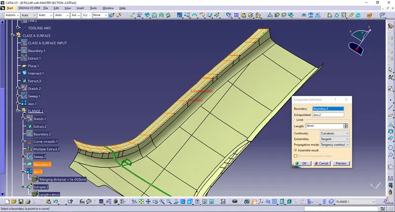
Then I have extrapolated the sweep to be able to trim the surfaces.
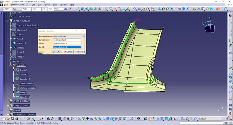
Then I have joined and extrapolate sweep.
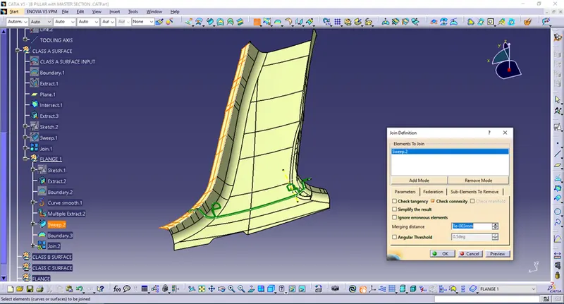
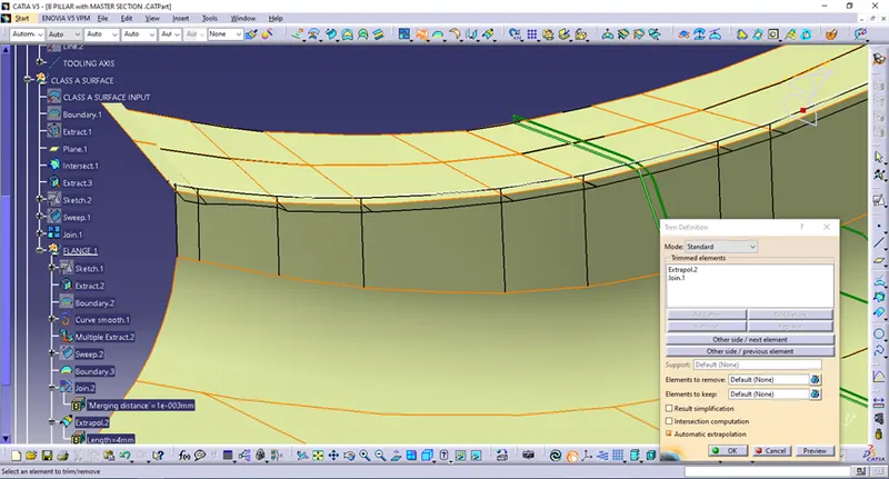
I have trimed the surfaces.
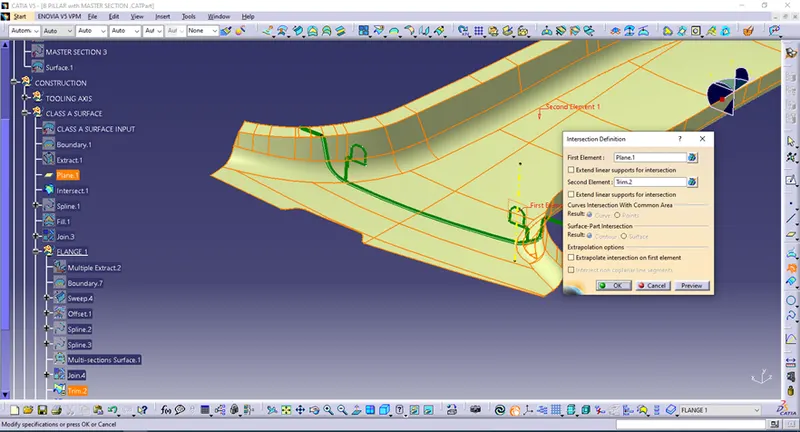
I will check sweep and Master Section once again (angle between them).That is why I will do intersect FLANGE 1 and plane.
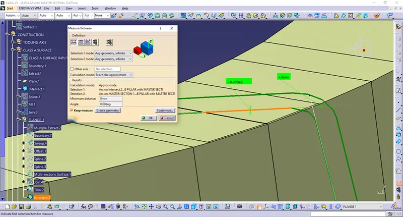
It can be seen that sweep in correlation to Master Section is well done.
Same procedure I will do for the other side.First I will insert new Geometrical Set FLANGE 2.
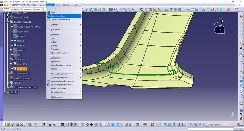
I will extract CLASS A SURFACES as shown.
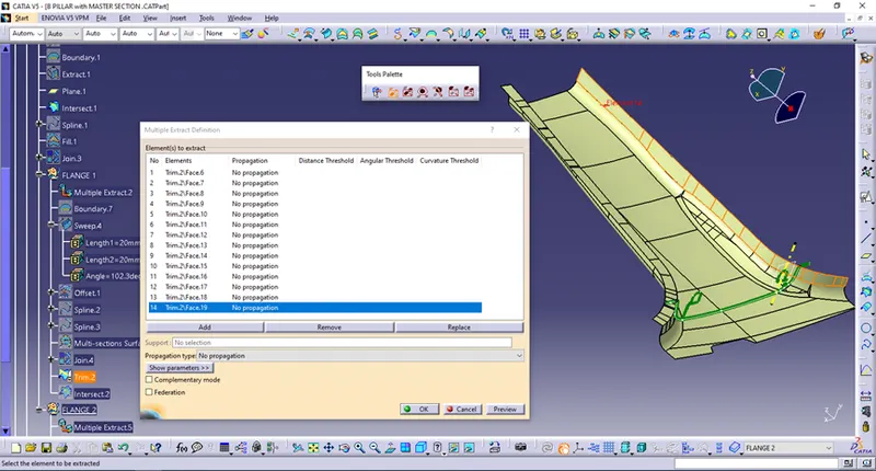
On the Extract basis I will make boundary.
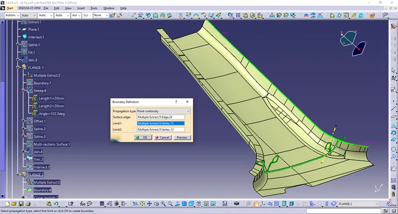
Then comes curve smooth.
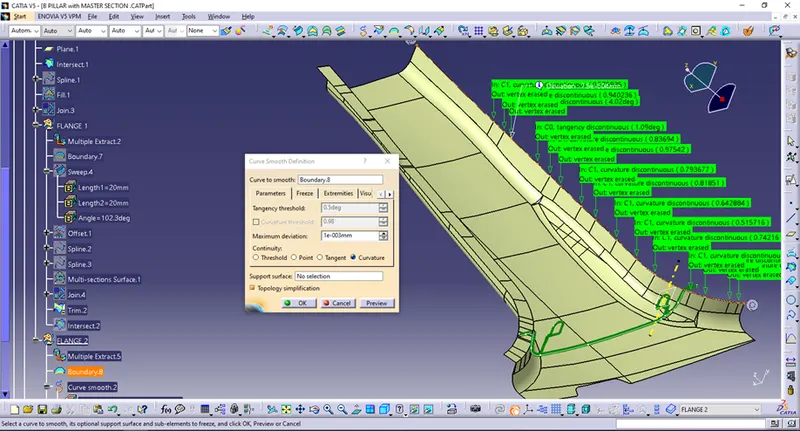
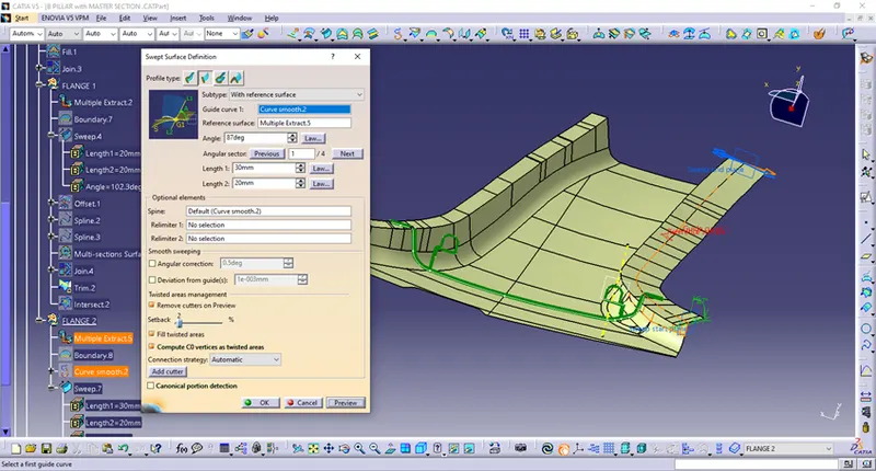
Afterwards I have make a sweep.
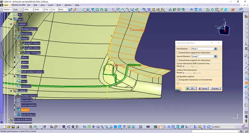
I have make intersect of FLANGE 2 and a plane in order to check and adjust sweep and Master section.
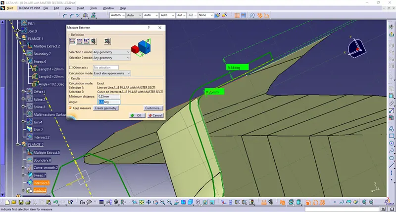
It can be seen,intersection is under 3.14deg angle from Master section – I should correct sweep.
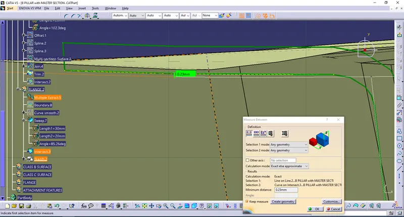
After the correctur I get a satisfactory result (0 deg between surfaces).
I have then trimed surfaces,but after I have done it there was a problem to fillet it,becuse after the sweep I could not do fillet because surfaces are we on the image right.
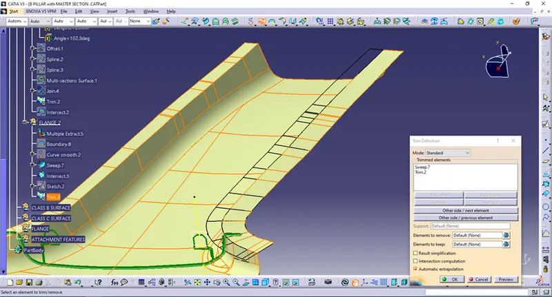
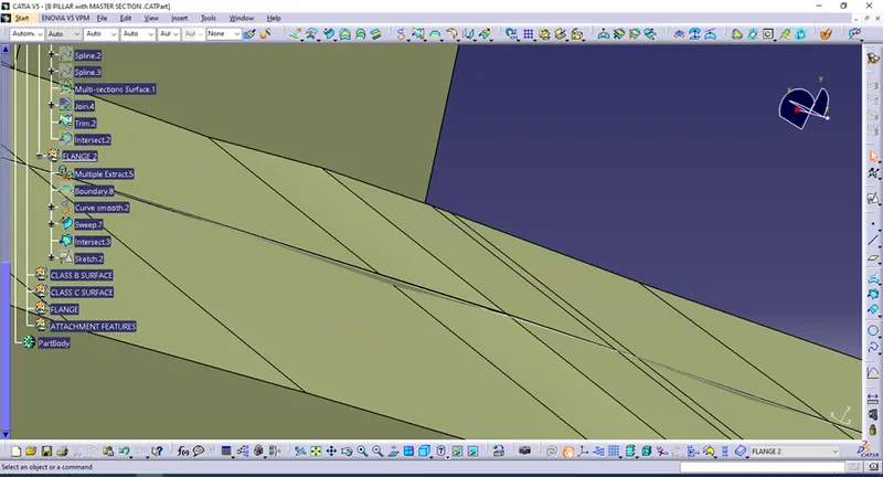
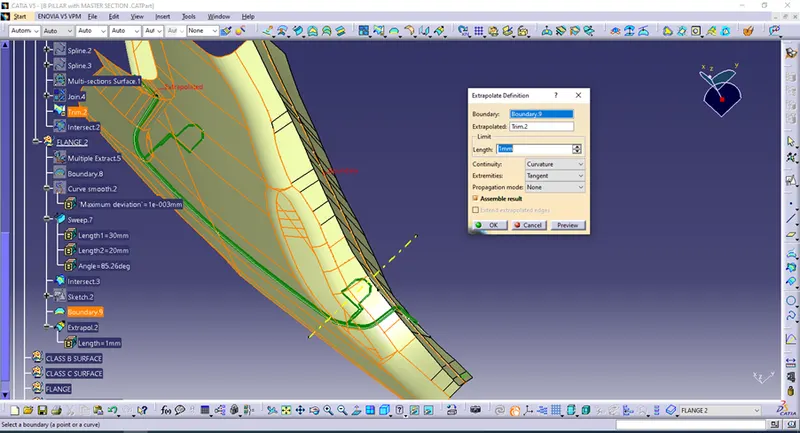
I have to extrapolate surfaces and trim them once again.
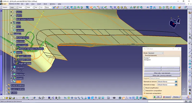
I have filleted the surface – and this is my improved CLASS A SURFACE (flanges inklusive) on the basis of Master sections.
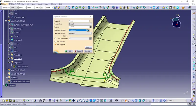
I have renamed EdgeFillet as a CLASS A SURFACE and changed its properties.
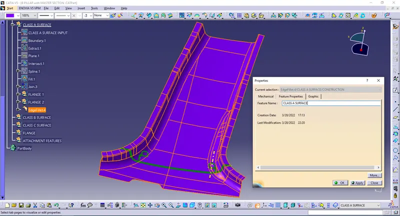
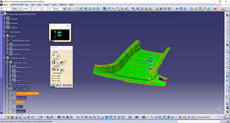
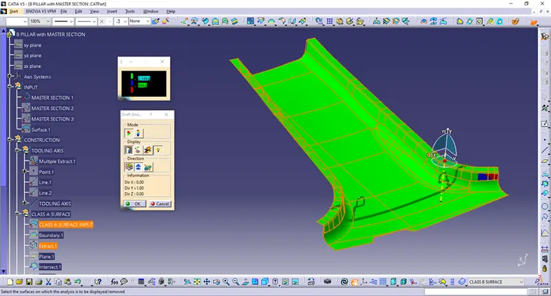
At the end of CLASS A SURFACE construction I should check it with Draft Analysis.
Once again it can be seen – TOOLING AXIS is defined with 0.5deg in the middle of 4 WAY LOCATOR (that have clearence 0.1mm...).
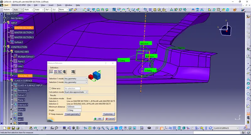
The part of CLASS A SURFACE that I have constructed,improved surfaces with flanges and fillets are well defined and the CLASS A SURFACE that is given it should be discussed with vehicle designer or tool department, that part of surface I am not authorized to change.
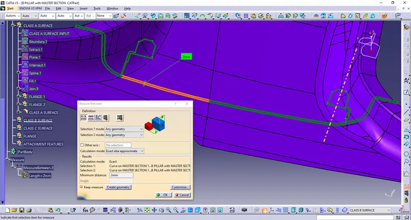
I should see what is thickness of the part from Mastersection and offseted CLASS A SURFACE for that value.Part thickness is 2mm.
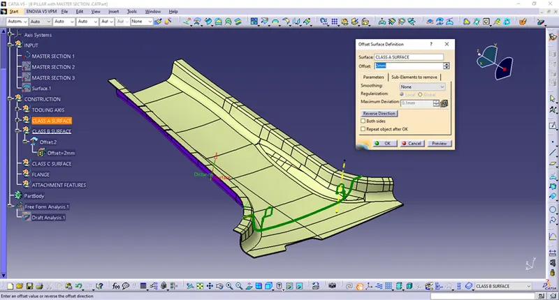
To get CLASS B SURFACE I should offset CLASS A SURFACE for a 2mm.
I would check offseted surface.As it can be seen there is one boundary on the surface I schould deal with it.
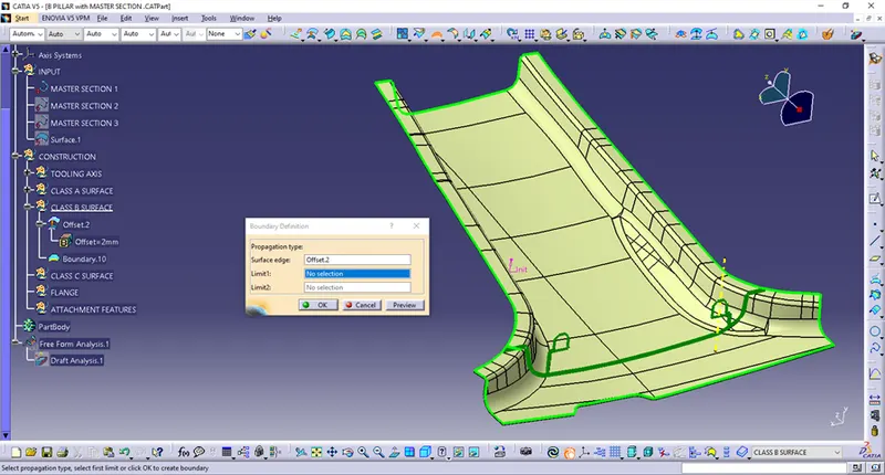
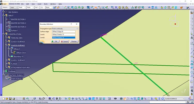
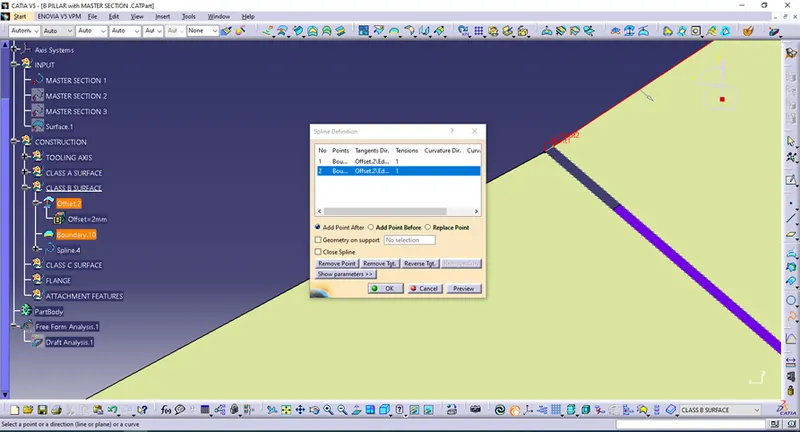
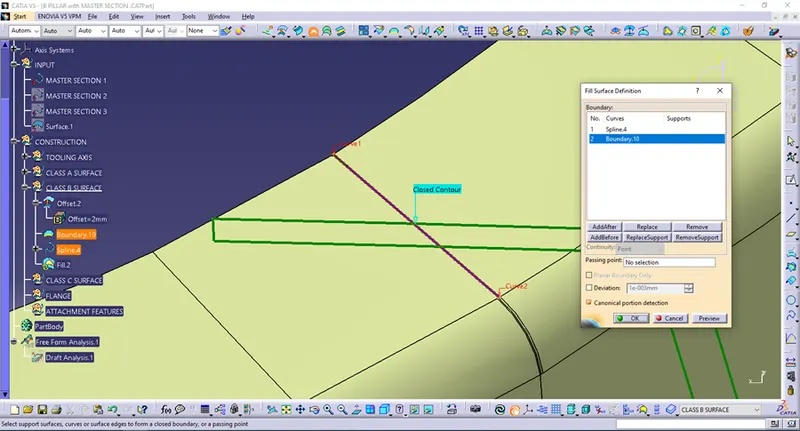
Then I have fill the gap and joined surfaces.
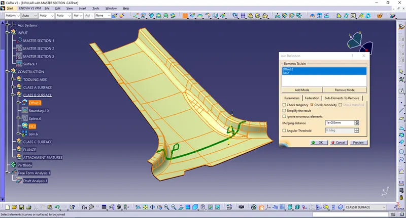
Check once again – now is all right.
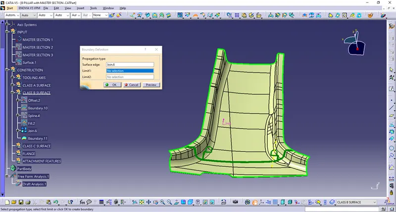
I will now extrapolate offseted surface as it is shown bellow.
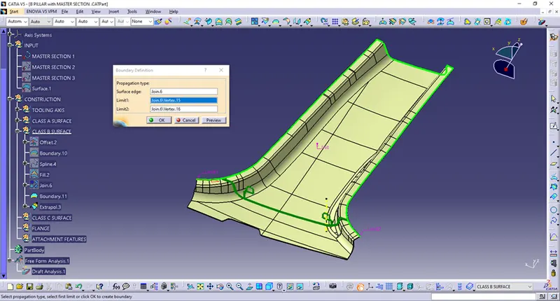
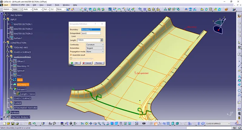
Here,as on image right I have tried to extrapolate that boundary,but it was impossible,it leads to cusp.
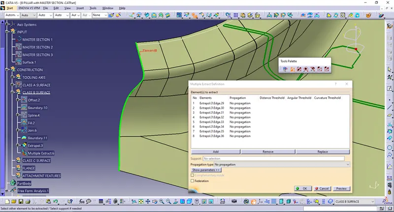
That is why I should build the boundary.
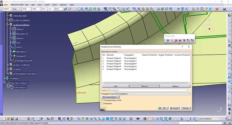
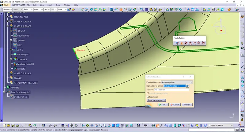
Now I am extrapolated that boundaries.
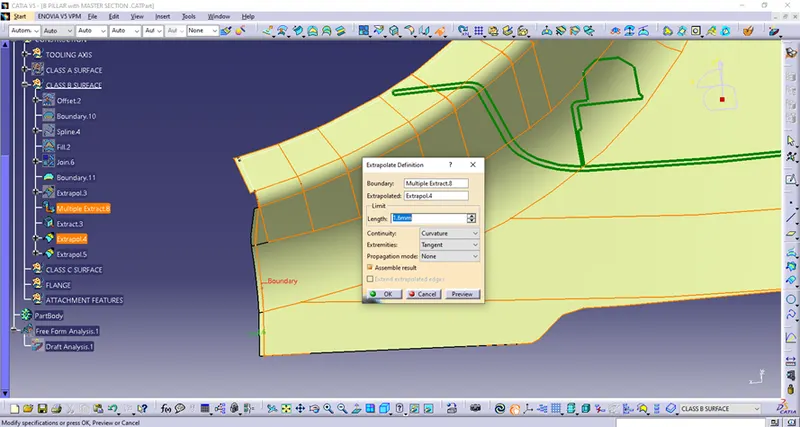
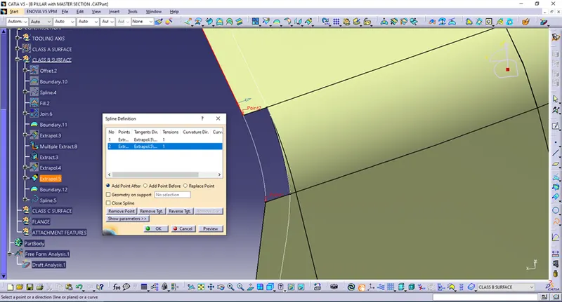
Then I have to deal with that extrapolation gap.
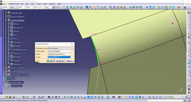
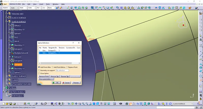
Then I have fill that gap and join that surfaces.
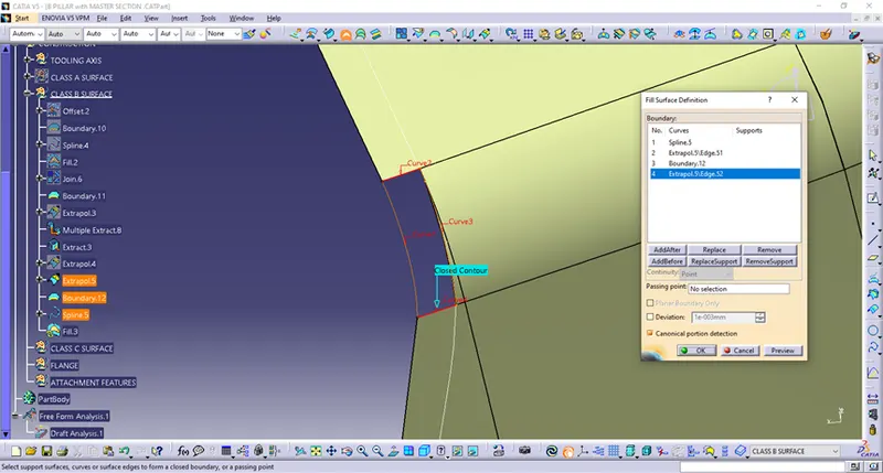
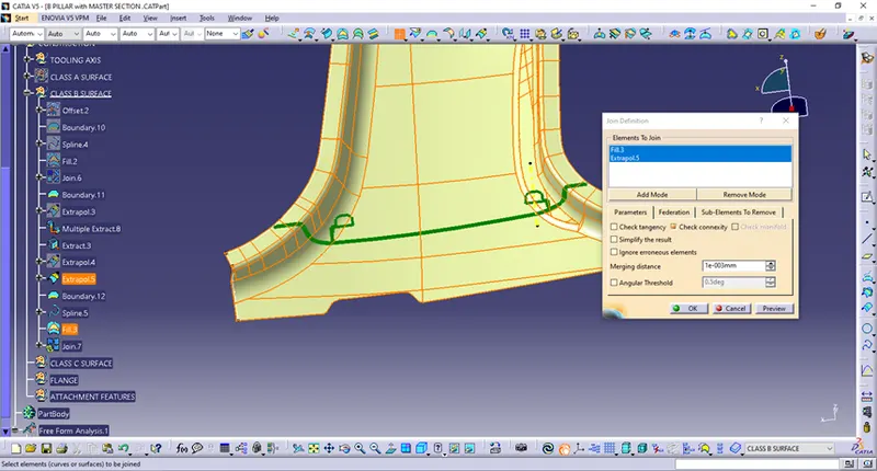
Finally I have extrapolated all offseted boundaries at the CLASS B SURFACE Geometrical Set.
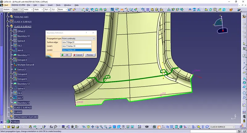
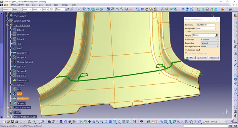
Now,under the Geometrical Set CLASS C SURFACE I am going to do a boundary on CLASS A SURFACE in order to make a Sweep on it.
First I have done boundary,then smooth curve and sweep on it.
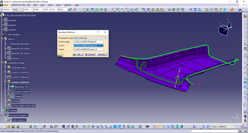
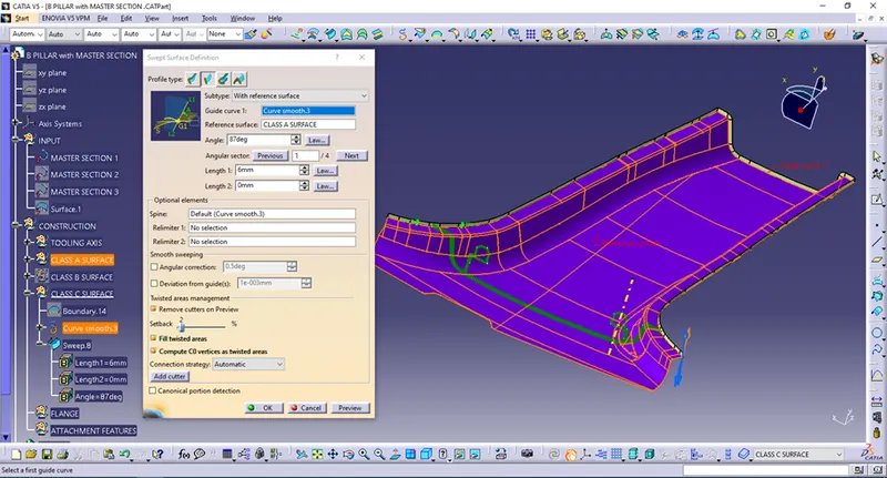
I will repeat procedure for the next boundaries.
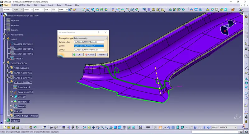
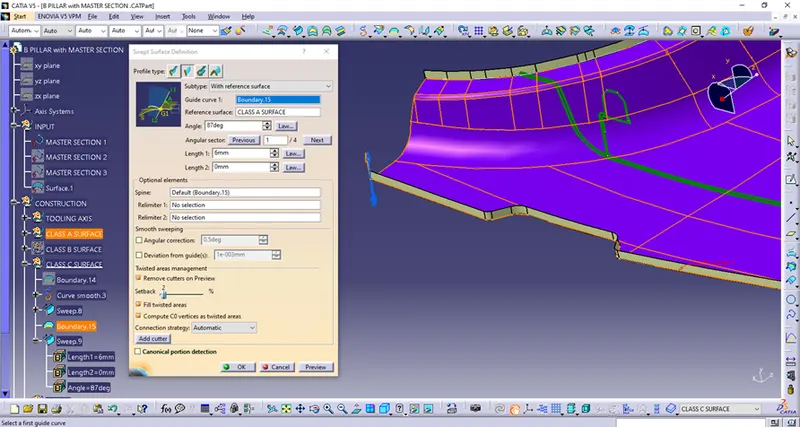
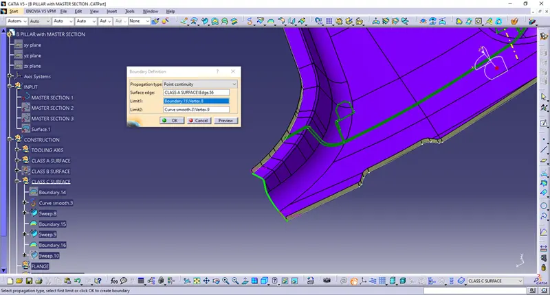
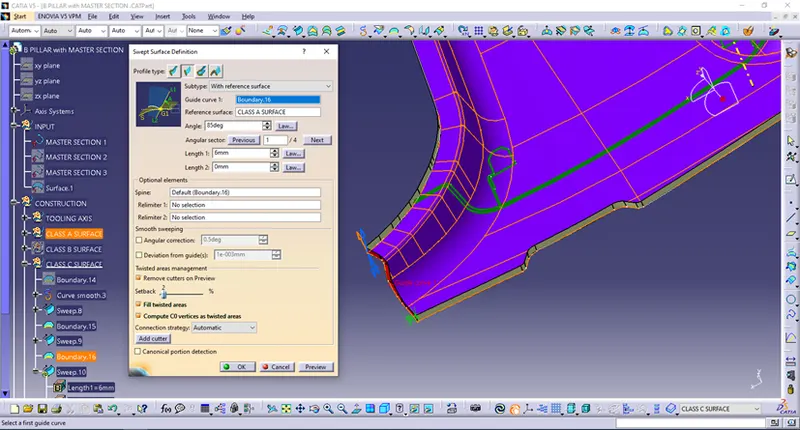
Then,I will close the gaps on the edges with the extrapolate – trim tools.
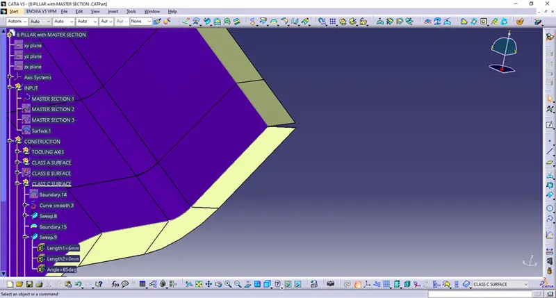
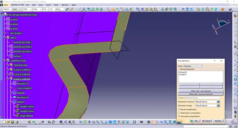
After a check,there were some imperfections – I am going to construct CLASS C SURFACE once again.
I have done boundaries as shown on images.
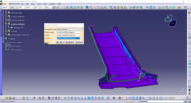
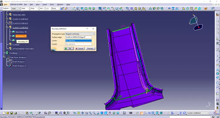
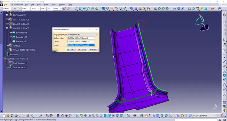
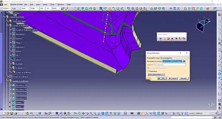
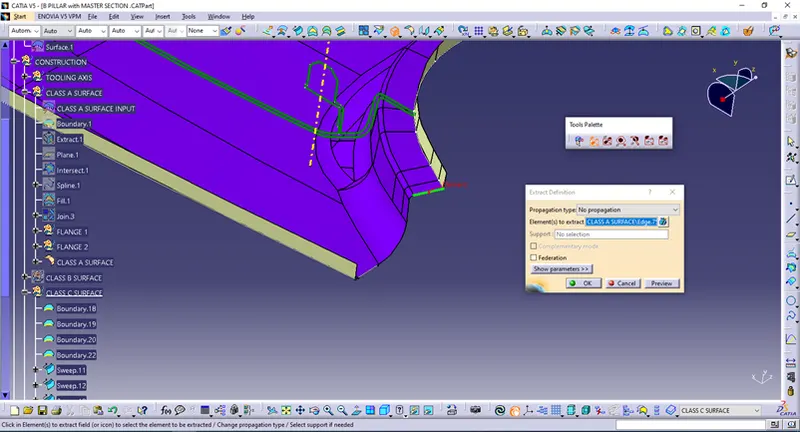
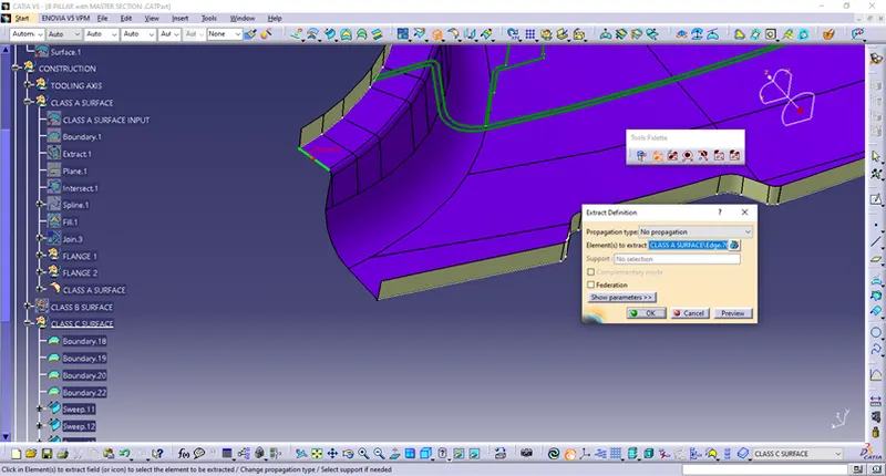
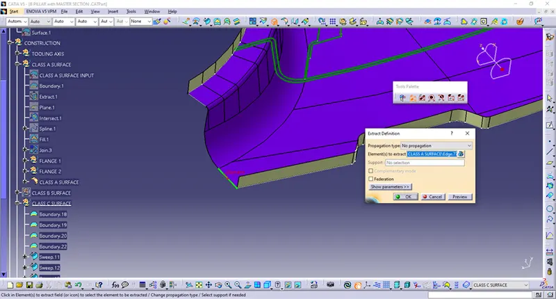
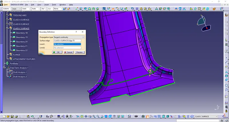
Now I am going to make a sweeps as follows.
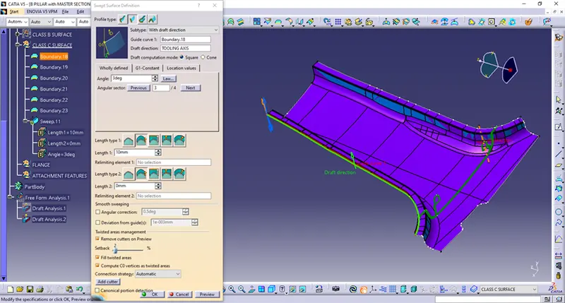
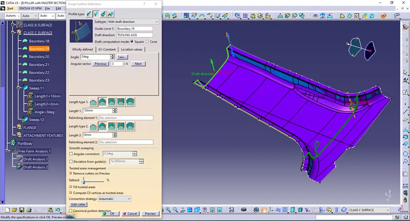
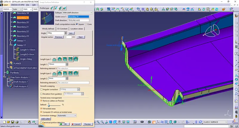
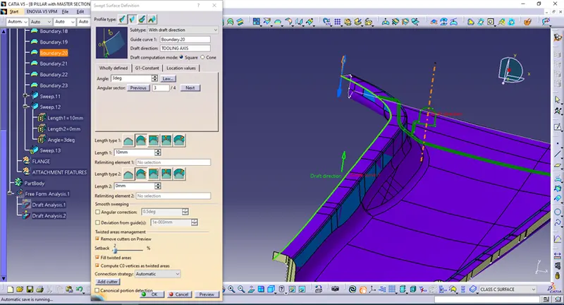
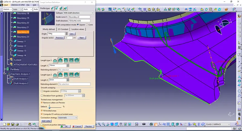
There are problems with the curves on sides,I should deal that on the other way – as it is shown bellow,with particular sweeps and multisections.
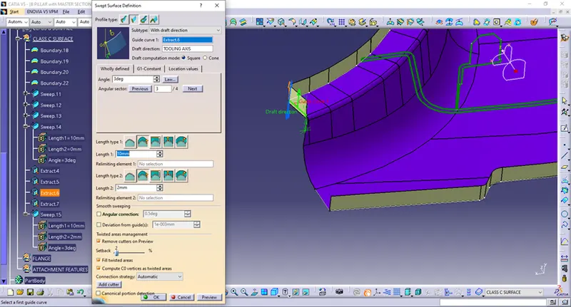
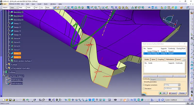
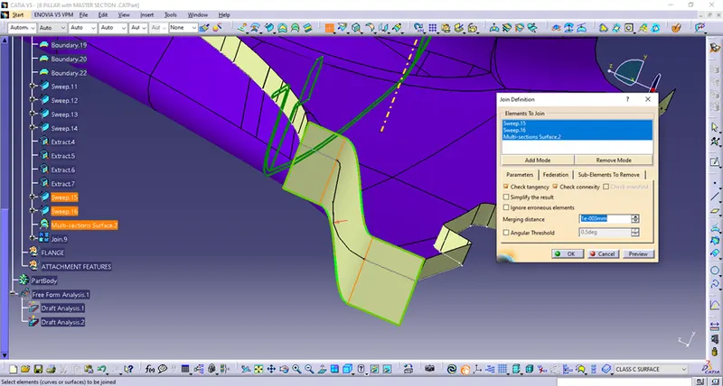
Then,I have to join those surfaces.
I am doing same procedure on the other side – extract lines,sweep with tooling axis and multisection on those sweeps.
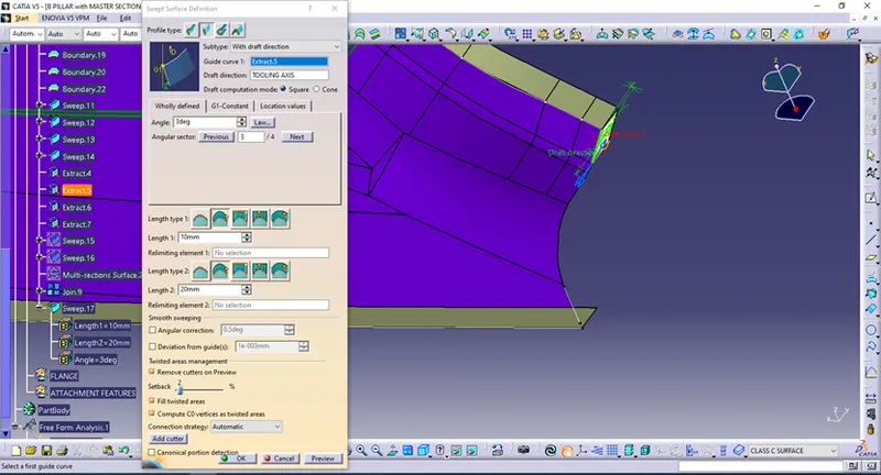
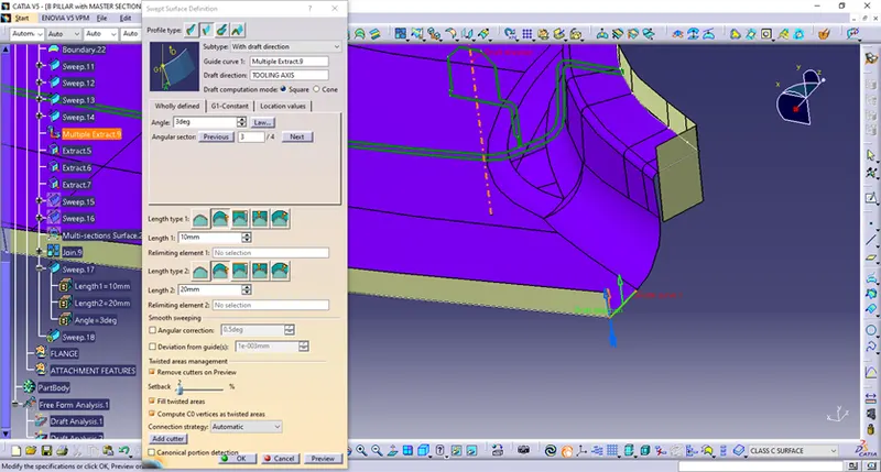
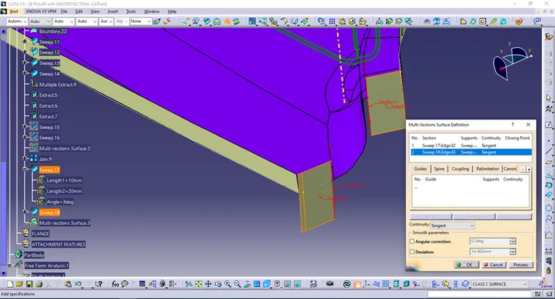
Now comes join of these surfaces.
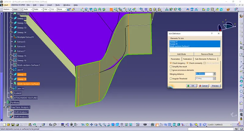
Then I have to extrapolate all those sweeps to close the gaps between them.
Afterwards I could trim them then.
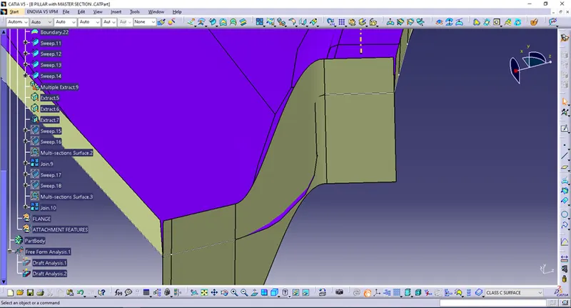
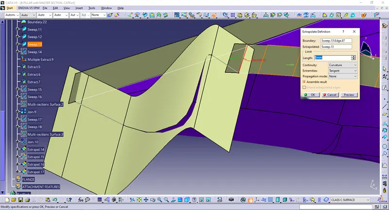
Then I have trimed surfaces.And that trim is my CLASS C SURFACE.
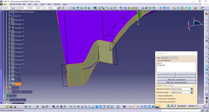
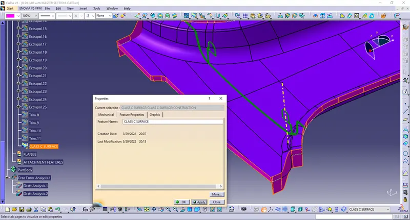
I have renamed that trim as a CLASS C SURFACE and change its properties.
Now I have to deal with Attachment Features.
From Mastersections it can be seen that, we are dealing with Screw Boss with 4 Way Locator on top.
That is why I am inserting Geometrical Sets SCREW BOSS and 4 WAY LOCATOR under ATTACHMENT FEATURES.
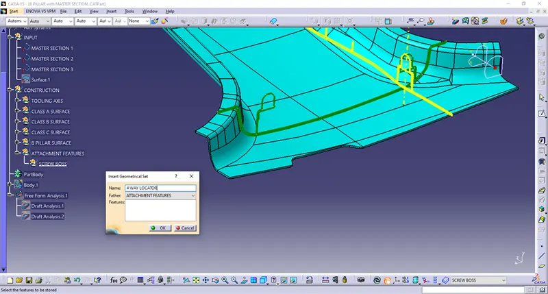
I am extracting line and in the middle of it I am inserting point and a plane on it as shown.
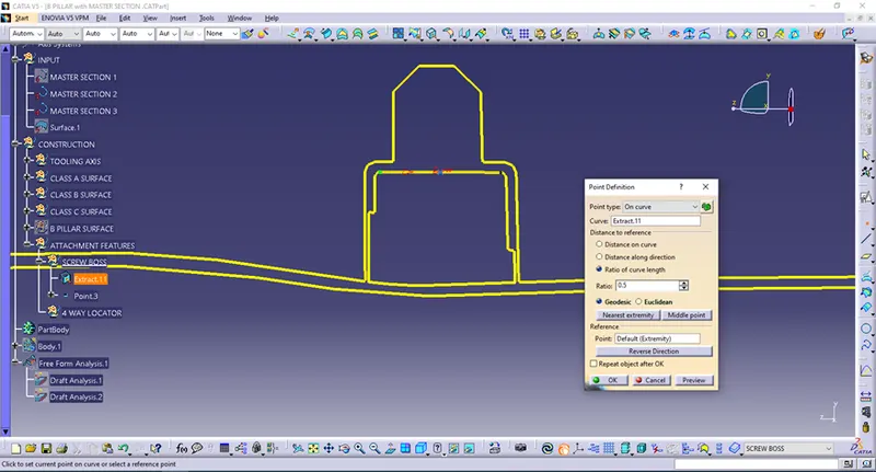
So,there is a point and a plane on it.
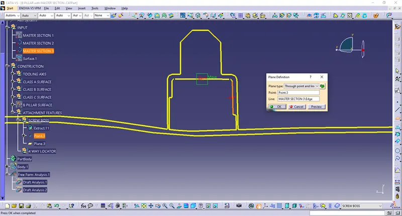
On that plane I have done projection of inner lines in Positioned Sketch and extracted them.
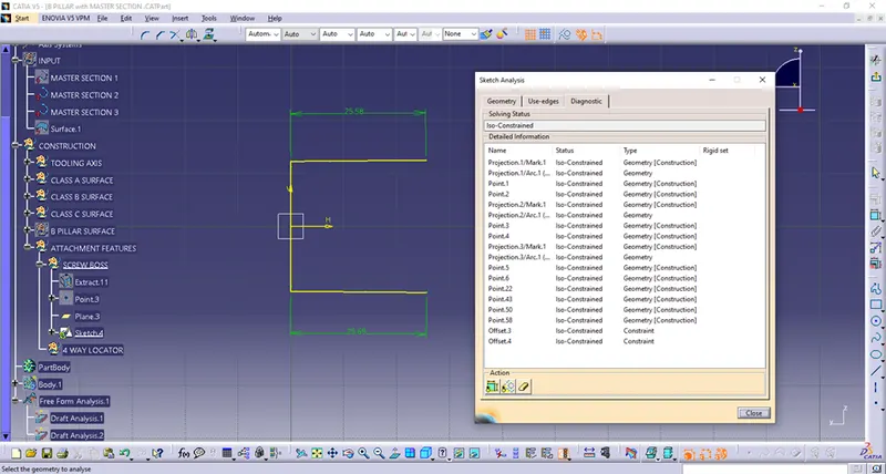
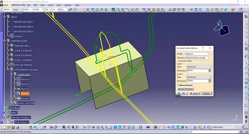
Then I am going to insert on previous point a plane and on the second Mastersection.
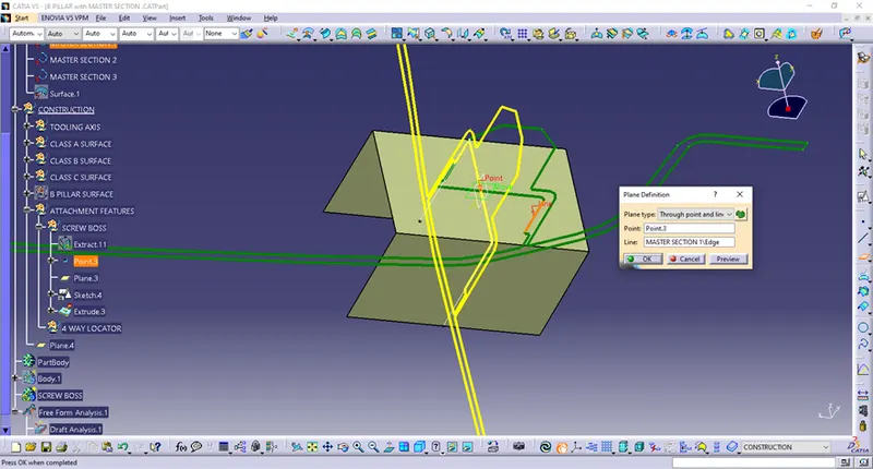
And I will extract lines as follows and afterwards do surface extract on that base.
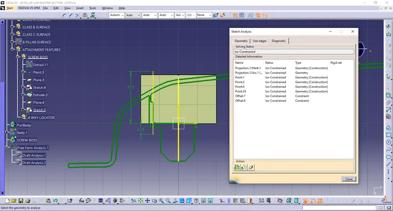
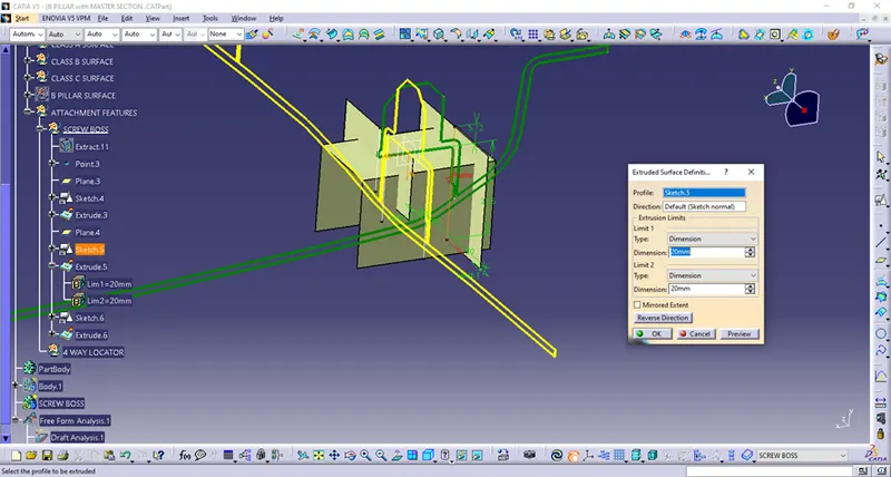
First I have trimed surfaces and then I have thicken it.At the end I have splited it.
That is why I should insert new Body – and I will rename it as SCREW BOSS.
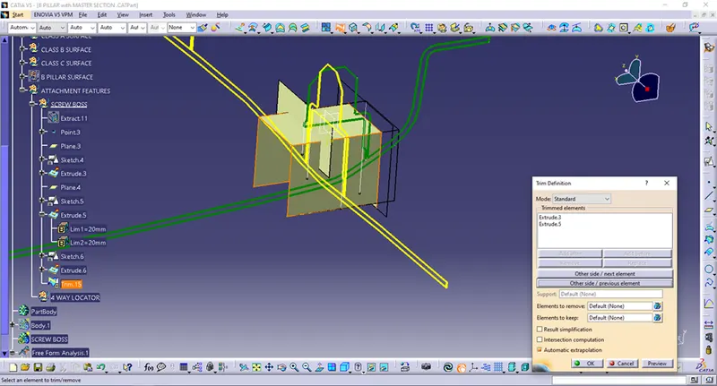
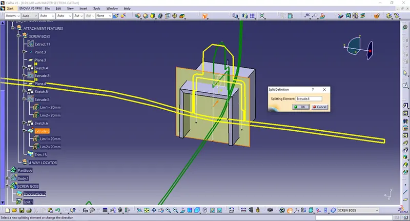
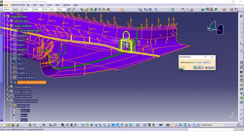
I have splited it with CLASS A SURFACE.
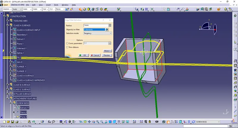
I have filleted it.
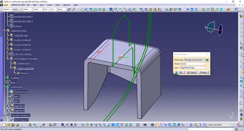
From Mastersection it can be seen that,on top of the SCREW BOSS I am having 4 WAY LOCATOR.
That is why I am in the Geometrical Set 4 WAY LOCATOR making Positioned Sketch as follows.
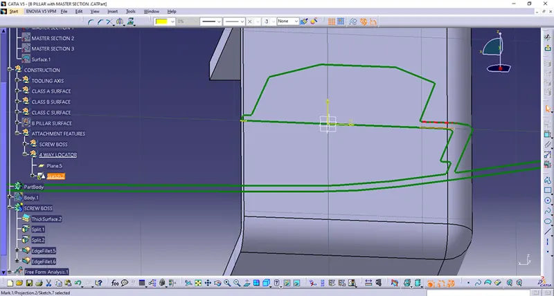
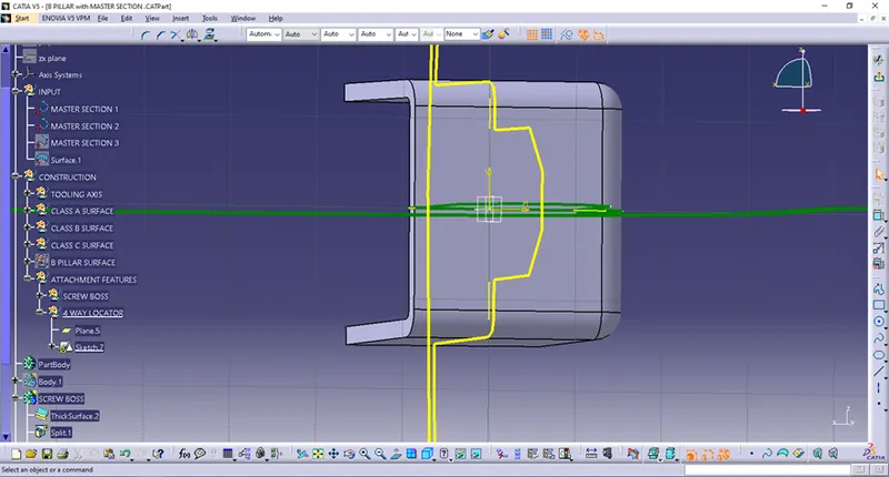
That projection lines are useful because that way I could see ribs edges.
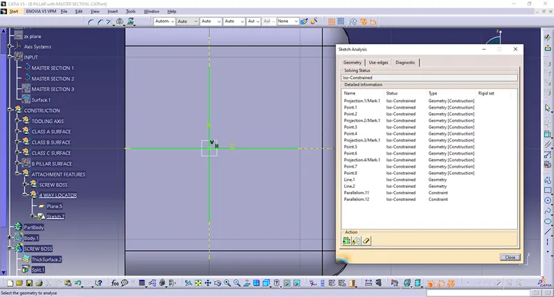
On that basis I have done ribs base.
I should insert new Body and I am renaming it as a 4 WAY LOCATOR.
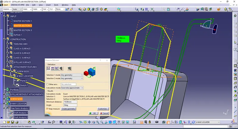
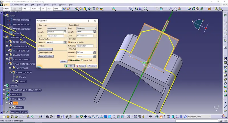
Then I have drafted and afterwards chamfered and filleted the ribs.
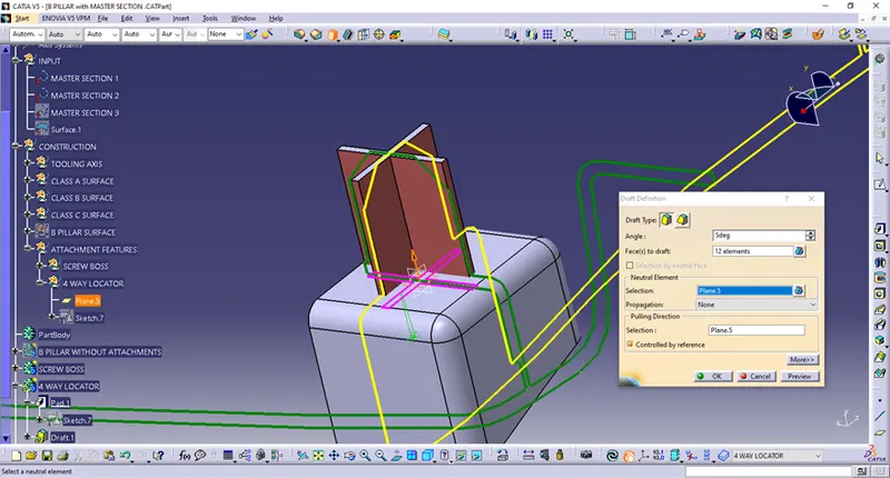
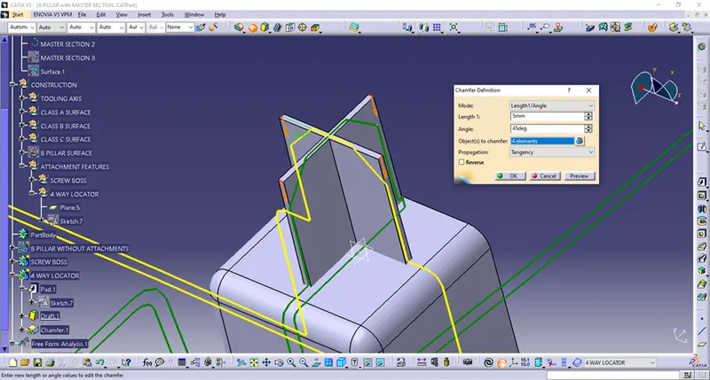
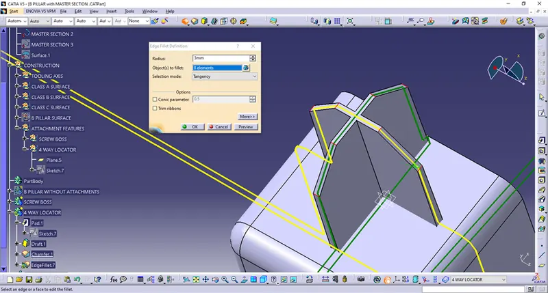
I have Union Trimed SCREW BOSS and 4 WAY LOCATOR to be able to add fillets,as it is shown on images.
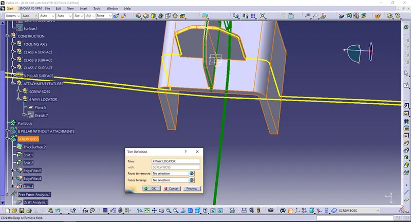
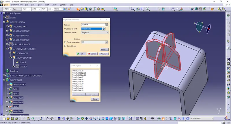
I should deal now with a bottom of SCREW BOSS,folowing the rules to avoid sink marks.
Therefore I will insert Geometrical Set SCREW BOSS BOTTOM and do the following operations as shown on images.
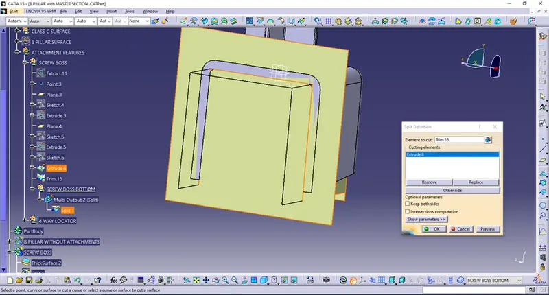
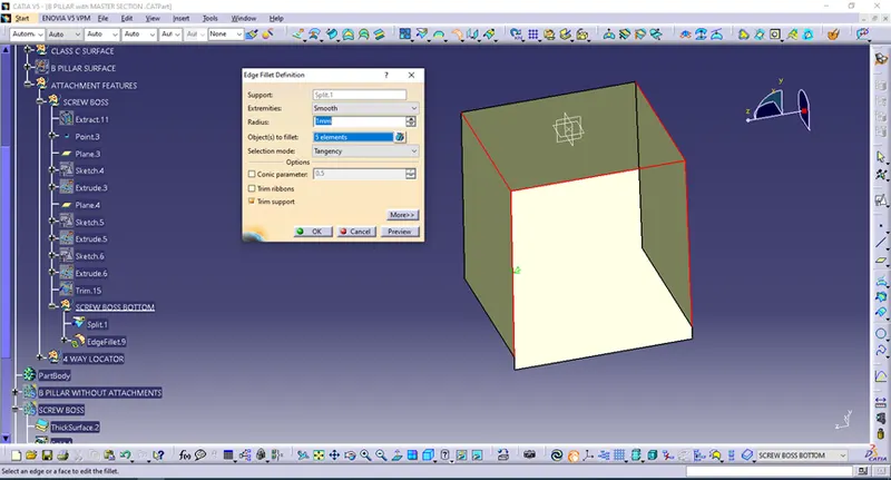
After Split I should do Fillet as on Solid part.
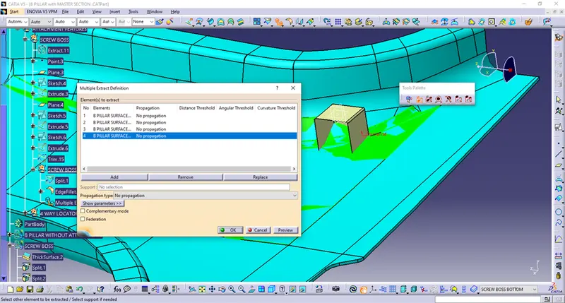
Then I will extract and offset CLASS B SURFACE.
After I have measured distance on Mastersection I have done offset with 4mm.
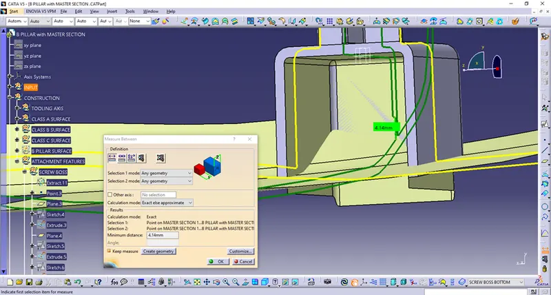
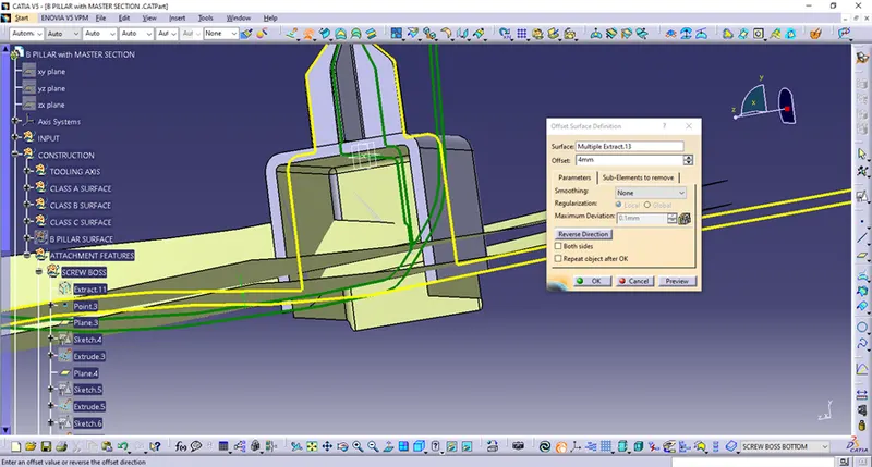
Then following the rule of bottom thickness (value for side offset should be 1,2mm (0.4 x 2mm (Part thickness),thickness value of side wall is 0.8mm.
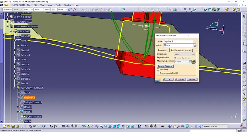
Now I am going to trim offseted surfaces and afterwards split it with Solid part to get bottom of SCREW BOSS.
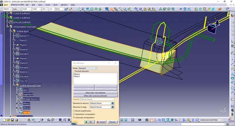
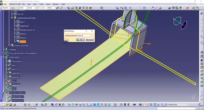
As it can be seen – that Feature is impossible to extract from Core/Cavity with that Tooling Axis,that means I should add one more Tooling Axis – I will name it as SIDE TOOLING AXIS,draft the Feature accordingly and then do Draft analysis and for that completed Feature – SCREW BOSS/4 WAY LOCATOR.
At first SIDE TOOLING AXIS construction – I will make it under TOOLING AXIS.
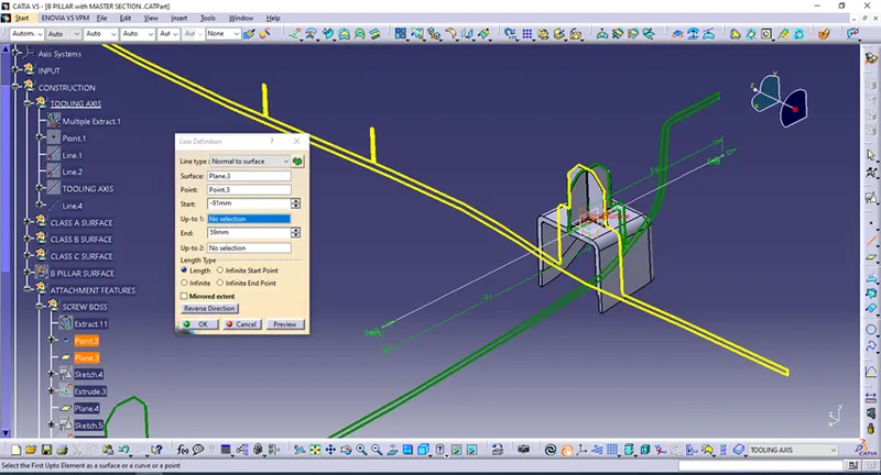
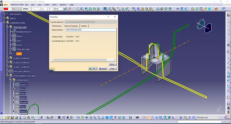
I am going to draft SCREW BOSS feature as is shown.
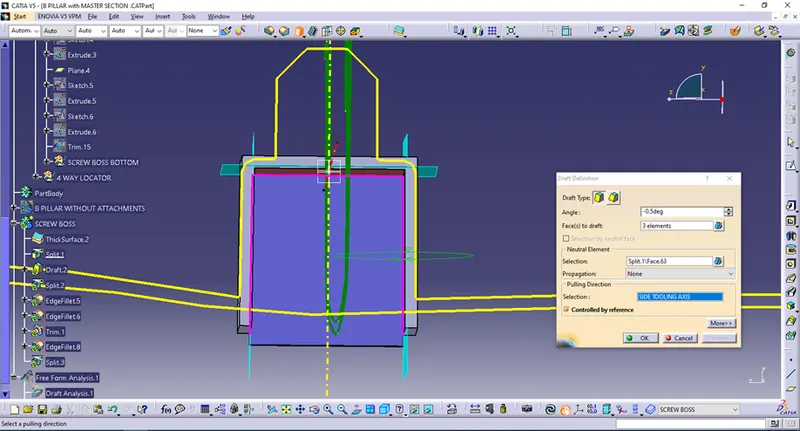
Draft is after little adjustment in structure done.It is clear with so offseted and cuted Feature I could not pull that Part out of mould – one more adjustment should be done.
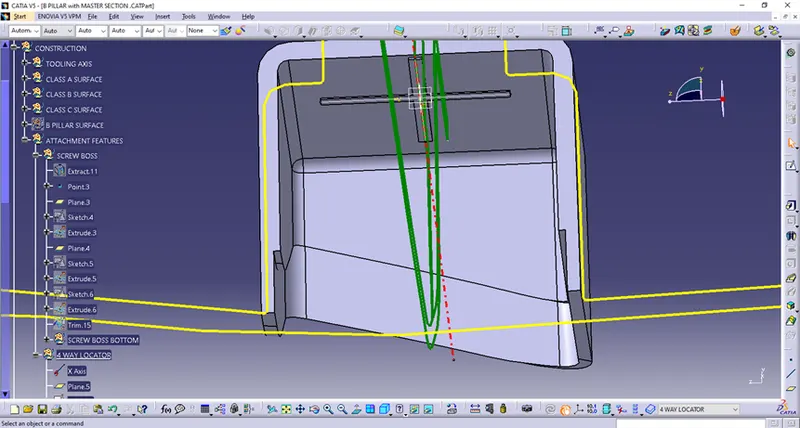
I have to reconstruct inner of SCREW BOSS as shown.I will first do intersect of surfaces.
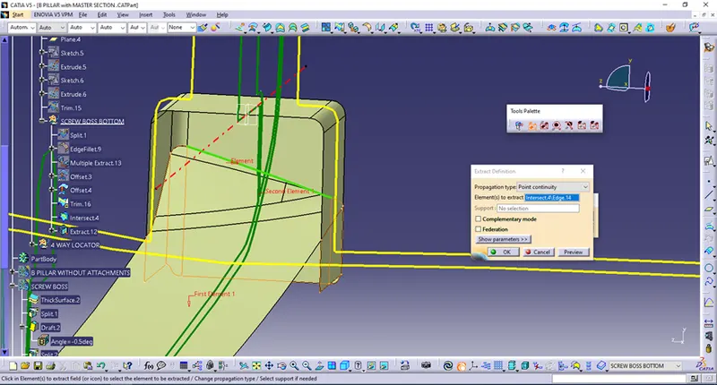
I am going to extract and extrapolate that intersect.
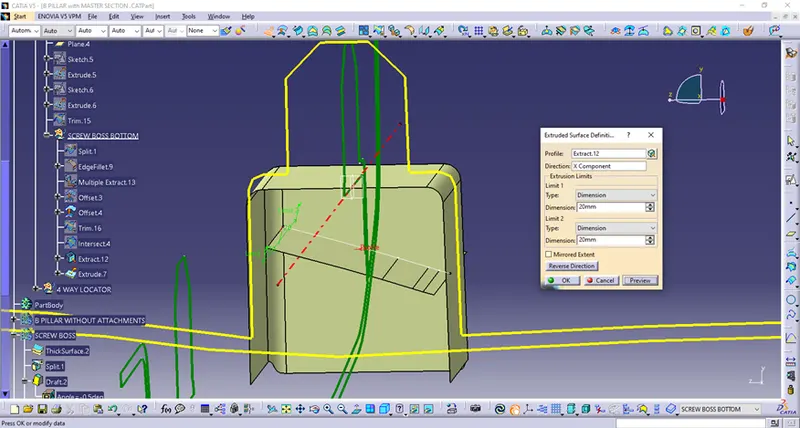
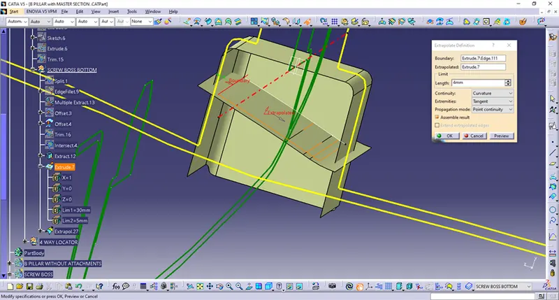
Afterwards I have trimed those surfaces.
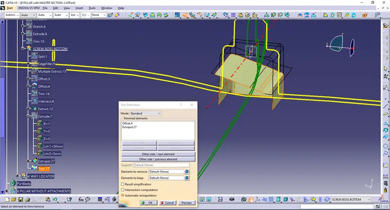
I have replaced Trim.16 with the new one Trim.17.
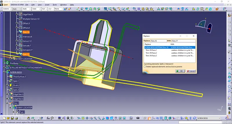
Now is good and I can draft and those surfaces.
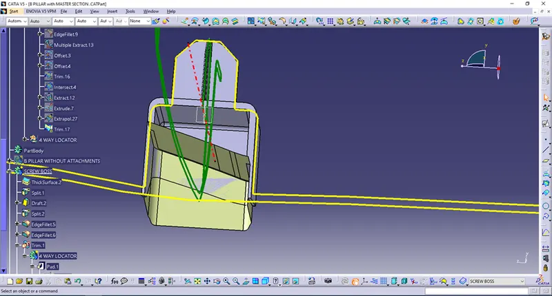
Draft is done also and on that surface.
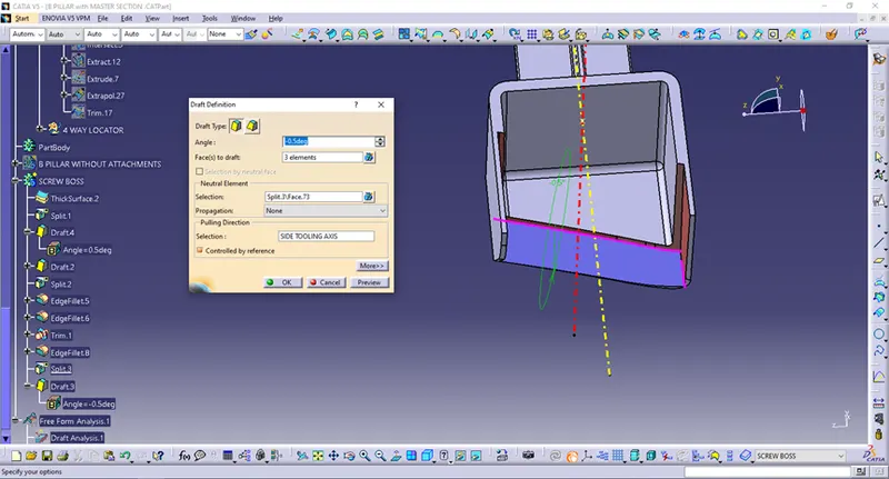
I have added fillets to the features.
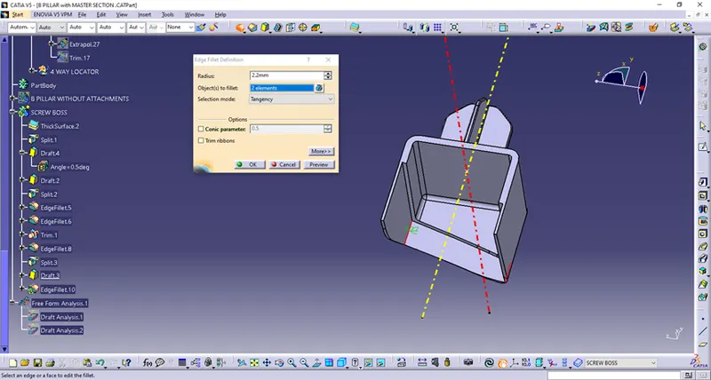
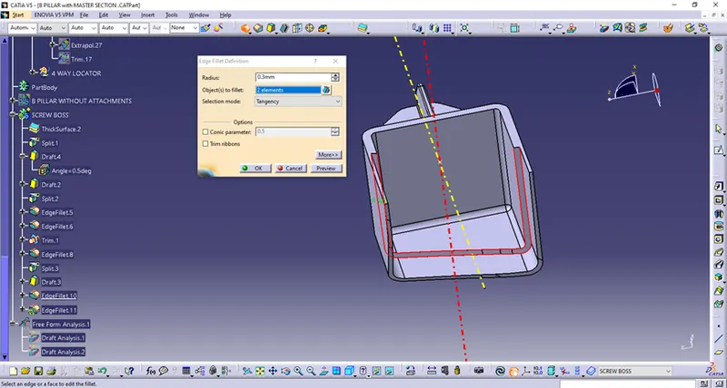
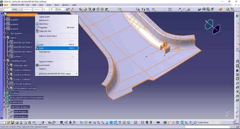
Now,I am going to copy – paste SCREW BOSS feature and positioned it on the other side.
In order to position part correctly I will insert a point between in the middle.
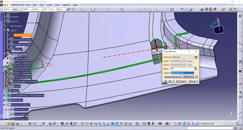
With symmetry I have positioned copied SCREW BOSS and renamed it as SCREW BOSS 2 (original I have renamed as SCREW BOSS 1).
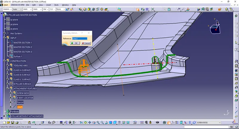
After positioning I have checked the feature – it is good positioned,thicknesses are good defined also.Here is needed correct bottom faces of the SCREW BOSS – I must once more extract CLASS B SURFACE,replace extract from other side and correct all what is needed to get a correct SCREW BOSS 2.
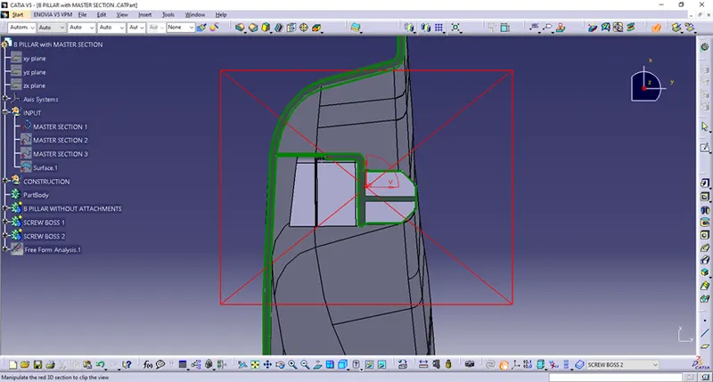
First I am inserting new Geometrical Set,renaming it as SCREW BOSS 2 and there I am extracting CLASS B SURFACE.
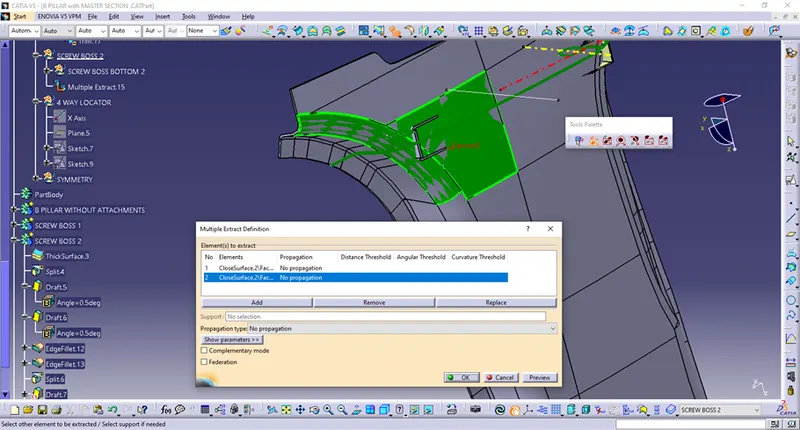
After extract and renaming from SCREW BOSS to SCREW BOSS 1 and SCREW BOSS 2,
Under SCREW BOSS 2 I am inserting Geometrical Set SCREW BOSS BOTTOM 2 and there I am copying necessery features from the previous geometrical set.
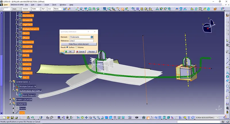
After symmetry I have isolated all these surfaces.
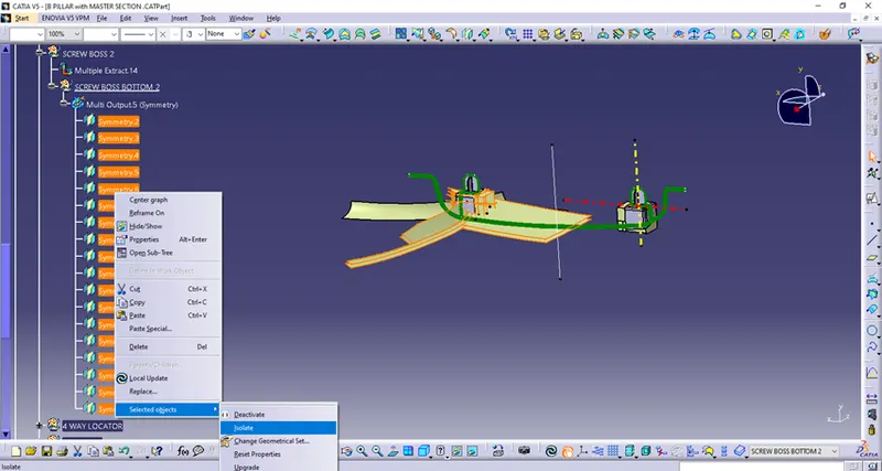
Then I have made adjustment and corrections with a new position.Afterwards
I have splited SCREW BOSS 2 feature with new extract.
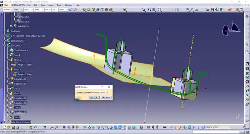
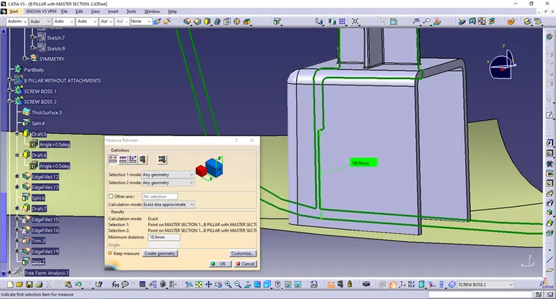
I have measured value for bottom surface offset.
I should offset it for 18.9mm and extrapolate that surface.
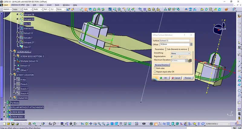
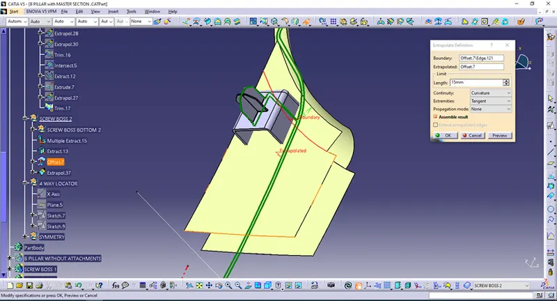
There will be problem with extracting that feature – I should do intersection then extraction and with that surface I am going to split solid feature.
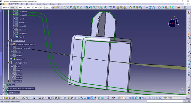
After I have made corrections, intersections,extractions and extrapolation I am geting surfaces needed for trim.
Thickness of bottom walls should be 0.4 x 2mm (Part thickness) and therefore inner surface should be offseted for 1.2mm.
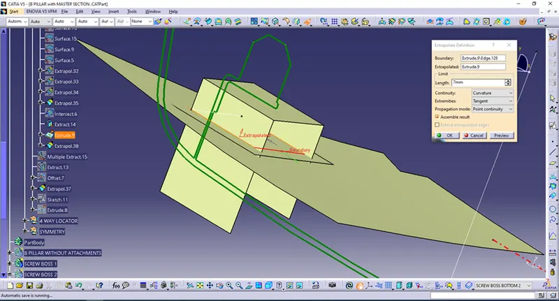
I have trimed surfaces first and then with it splited Solid Features.
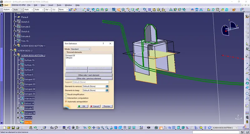
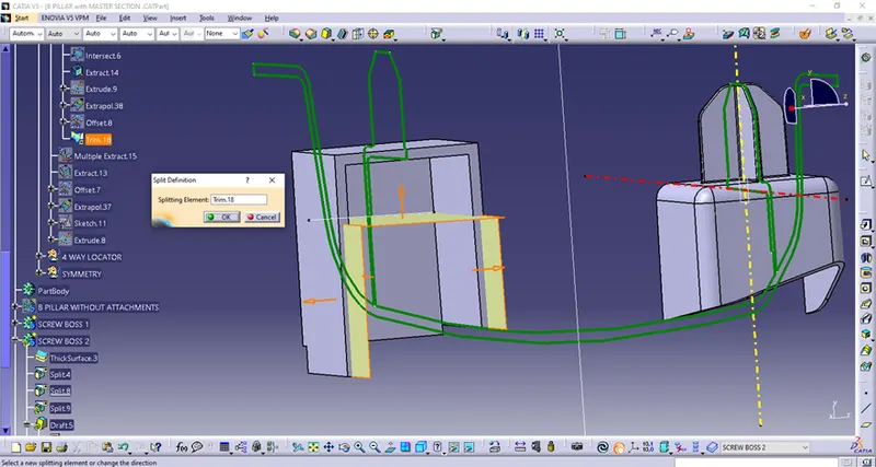
Then I have activated Drafts and Fillets as shown on images.
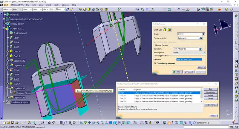
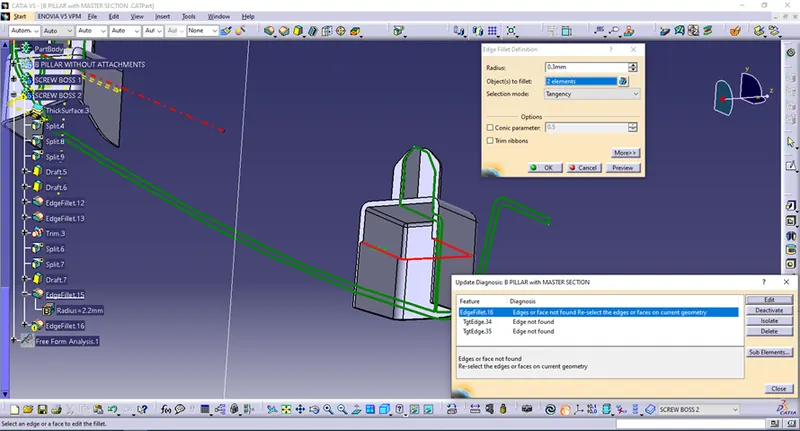
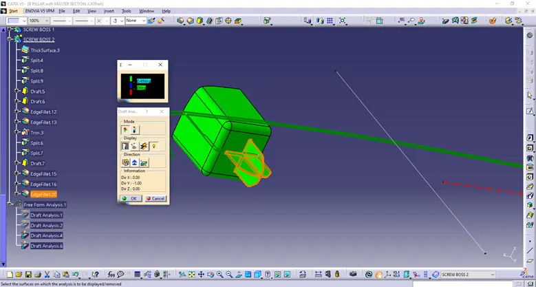
In conclusion to SCREW BOSS 2 feature I will make Draft Analysis with
MAIN TOOLING AXIS
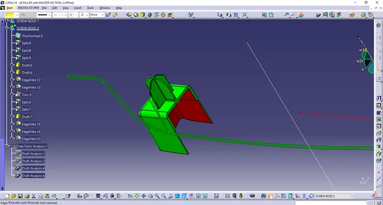
SIDE TOOLING AXIS
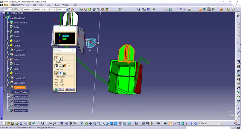
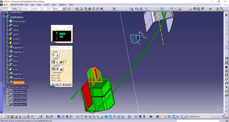
It could be seen SCREW BOSS 2 is well defined,it passes Draft Analysis.
I am going to make last feature – RIB.
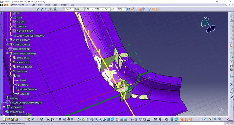
Therefore under ATTACHMENT FEATURES I am inserting new Geometrical Set with a name RIB and there I am making Positioned Sketch as follows.
There are pair rules they I should obey – distance between Features should be cca. 50mm (to avoid sink marks and flow lines) and Rib thickness is 0.4 x 2 (Part thickness) = 0.8mm.
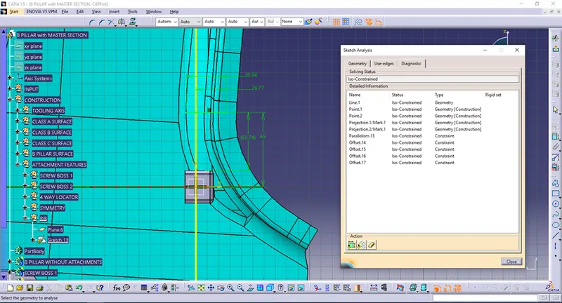
I will extract CLASS A SURFACE and extrude the line.
Length of the RIB is not given,I will make it approximately 20mm.
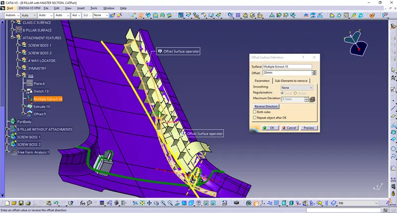
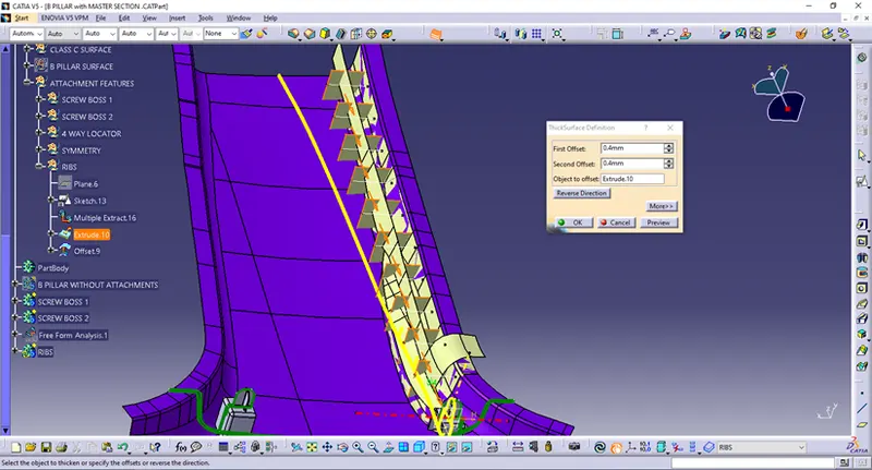
I am going to offset CLASS A SURFACE for 20mm and thicken extract for 0.4x2mm.Therefore I should Insert another new Body and rename it as RIBS.
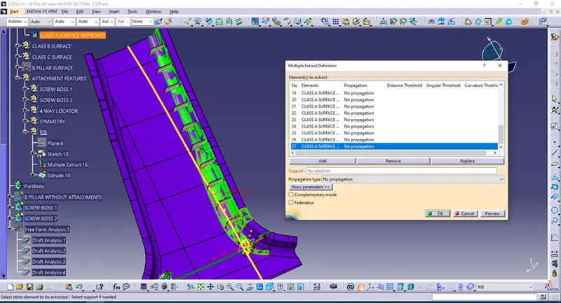
Actualy,I am also going to correct my Positioned Sketch in RIBS Geometrical Set and add more lines to make extract and to define all Ribs in that sketch.I will also expand MultipleExtract along with it.So is faster and more efficient.
After I have done adjustment on surfaces I am going to draft and split them.
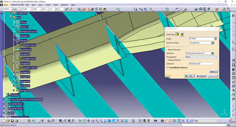
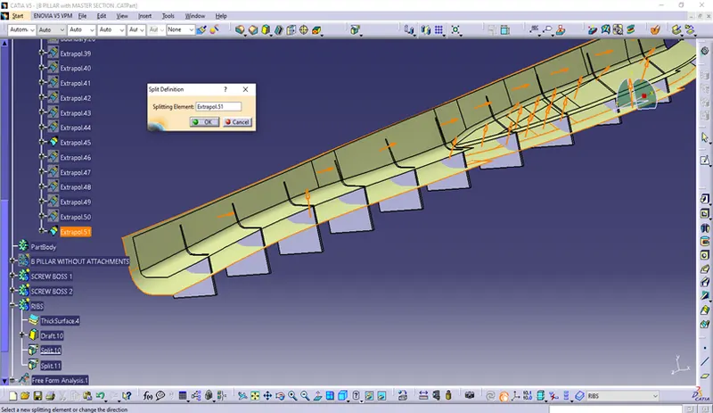
I am going to make now Draft Analysis for RIBS.
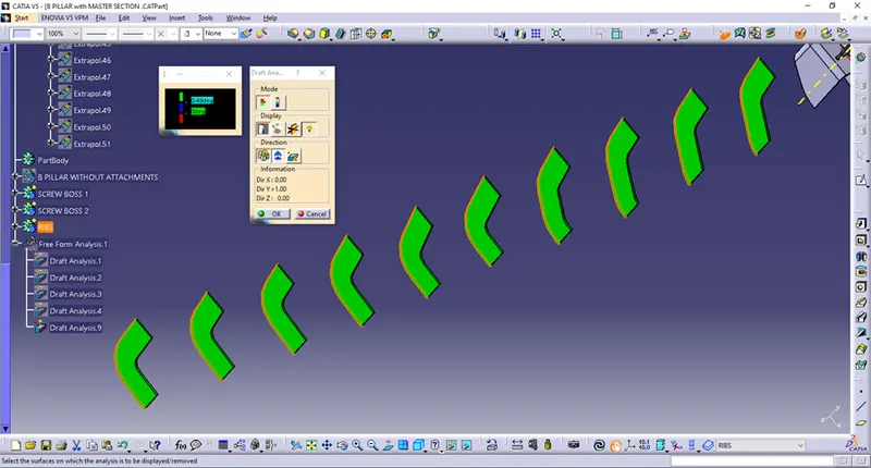
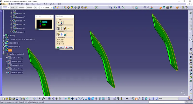
It could be seen,that all Drafts are good defined.
I am going to assemble all those Features under one – B PILLAR (so I have renamed Part Body).
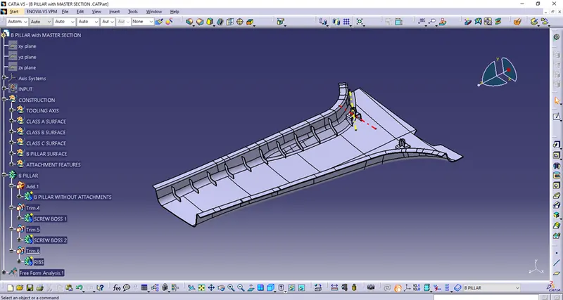
I am going to do some filleting on RIBS and bottom of CLASS B SURFACE.
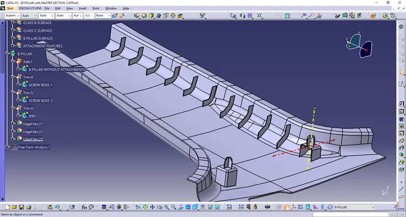
Finally I will do Draft Analysis with all those Features.
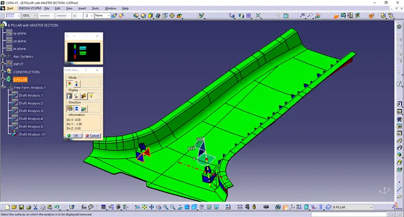
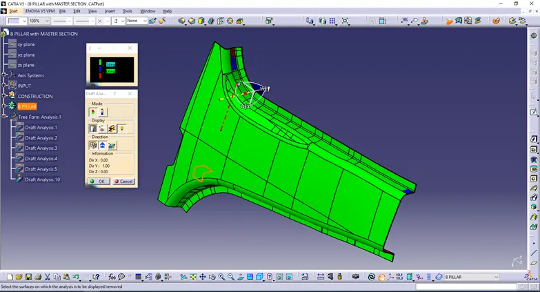
It can be seen Drafts are good defined,there is a little bit of imperfections on CLASS A SURFACE,there should be clarified with Vehicle Design Engineer.
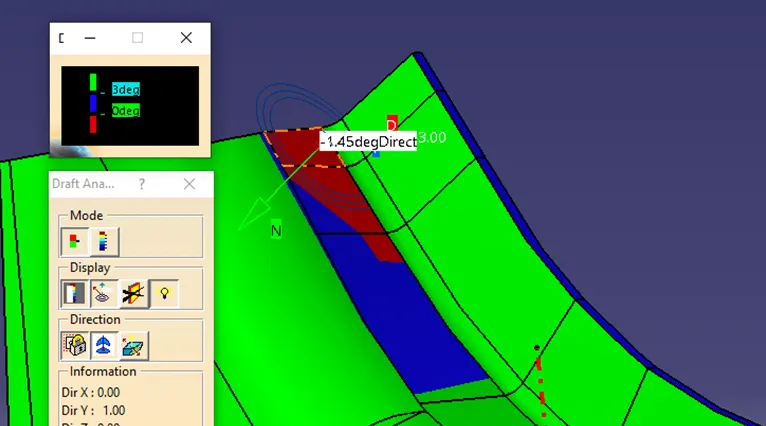
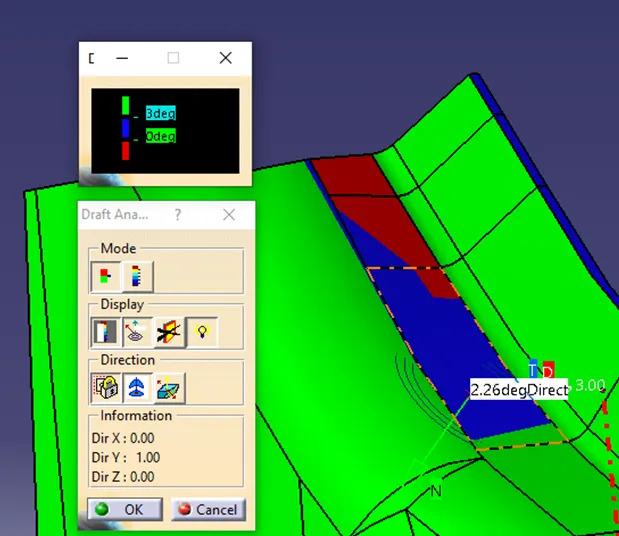
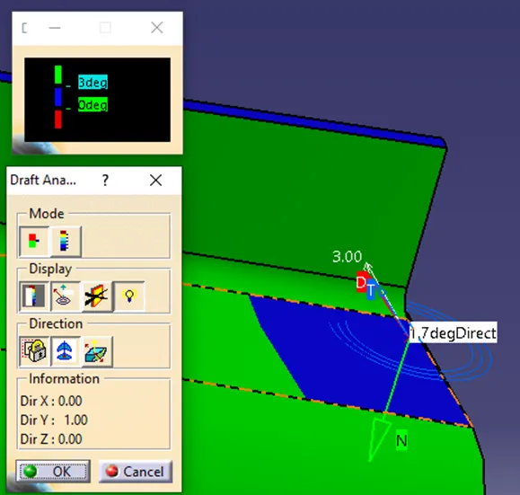
Draft Analysis with MAIN TOOLING AXIS shows that all drafts are satisfactory (except the one with imperfections of CLASS A SURFACE).
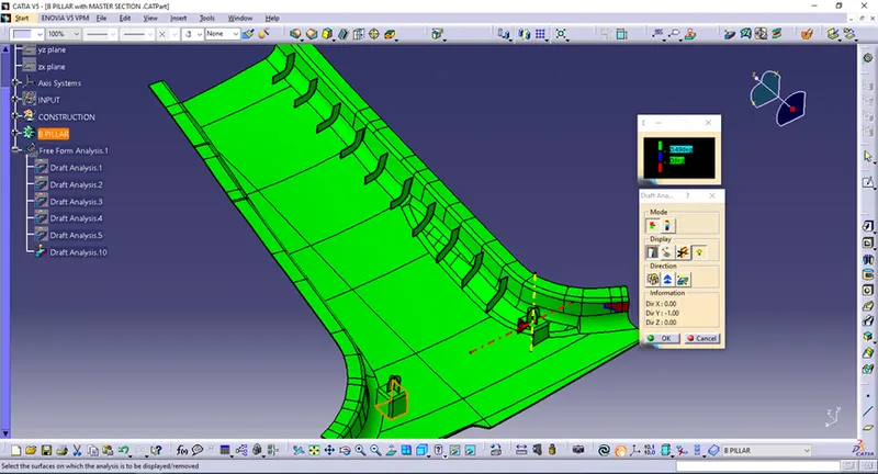
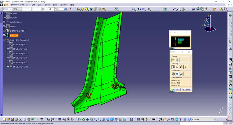
Now,I will do Draft Analysis also for a SIDE TOOLING AXIS.
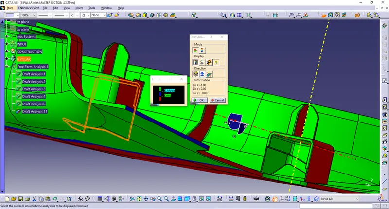
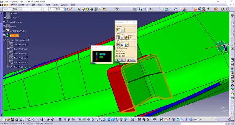
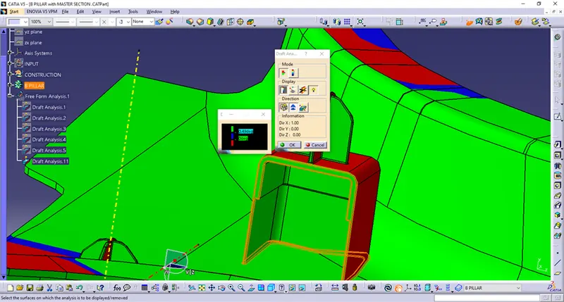
So,on the basis of given Input I have constructed CLASS B SURFACE,CLASS C SURFACE,then close surfaces to get B PILLAR WITHOUT ATTACHMENTS.Afterwards I have done and attachments – SCREW BOSSes with 4 WAY LOCATORs and RIBS and joined all in one Solid part – B PILLAR.
I have done Draft analysis separately for every singular Part and in conclusion with all Parts together.
That is all fellows.
Best regards,
Ivan Tole