Week 8 - Challenge 5 - Core & Cavity Design
Hi guys,
I will explain procedure of making Tooling Axis and a Draft Analysis of the Surface and the Part.
TOOLING AXIS
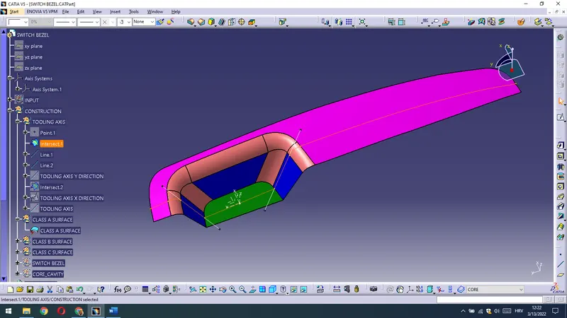
At first I have inserted Axis System on the bottom of the CLASS A SURFACE as shown and then I have made a intersection of the YZ plane and a CLASS A SURFACE.
Then on the basis of the intersection curve I have drawn two lines (Line.1 and a Line.2)
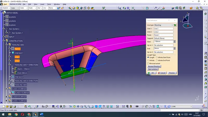
Then between those two lines I have drawn bisecting line to get a TOOLING AXIS Y DIRECTION.
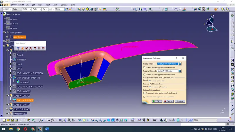
Then I have made intersection of the CLASS A SURFACE and a XZ plane and on the XZ plane made a Positioned sketch regarding that intersection.
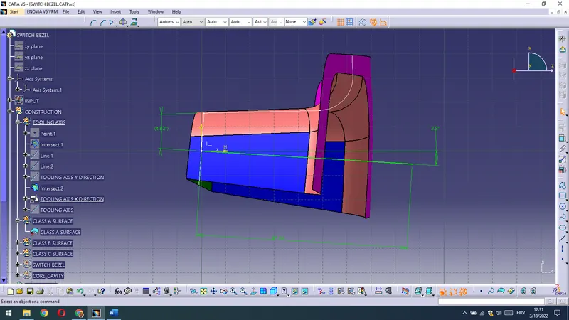
So,I got a TOOLING AXIS X DIRECTION.
On the basis of TOOLING AXIS X DIRECTION and a TOOLING AXIS Y DIRECTION I have made bisecting line and got a TOOLING AXIS for given surface CLASS A SURFACE.
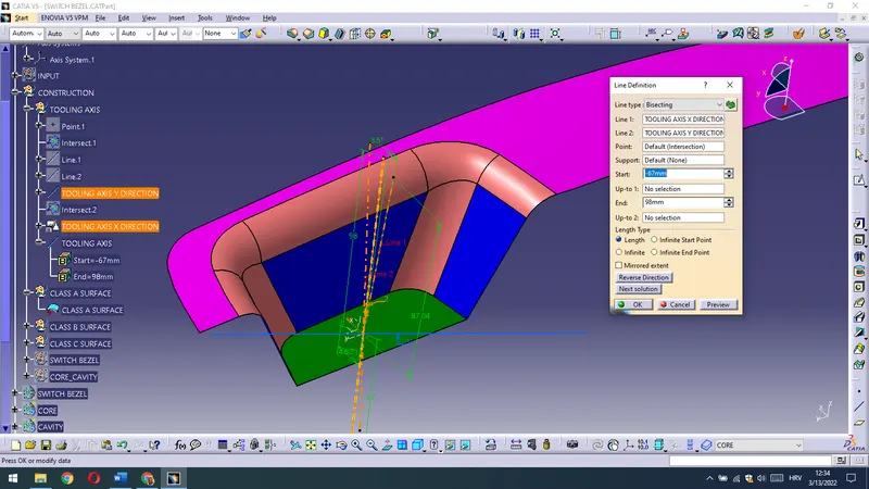
That is my TOOLING AXIS.
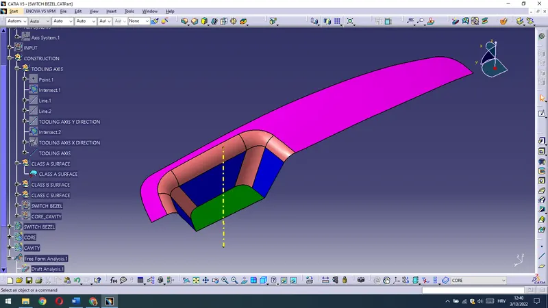
On the basis of CLASS A SURFACE and TOOLING AXIS I have made a Draft Analysis as follows.
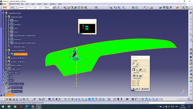
So,with that TOOLING AXIS drafts are greater than 3deg,all is good,I can go with the next step.I have Published TOOLING AXIS and CLASS A SURFACE.
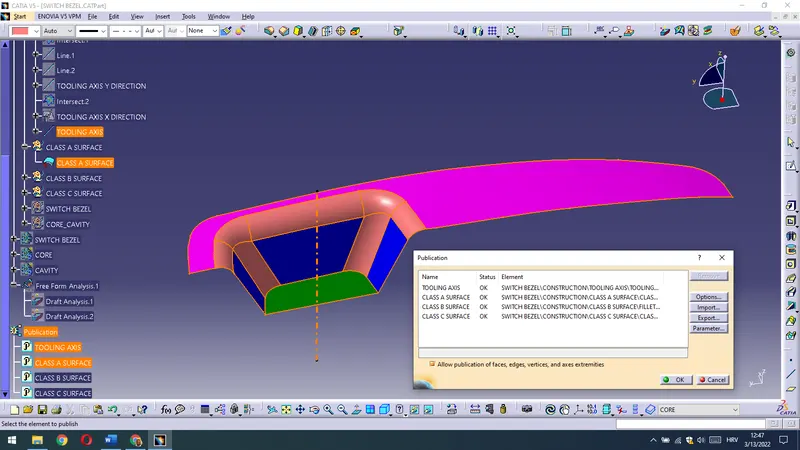
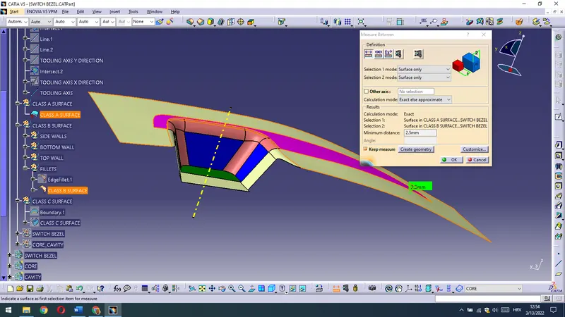
On the basis of the CLASS A SURFACE I have constructed CLASS B SURFACE as shown (offseted for a 2.5mm downwards regarding CLASS A SURFACE).
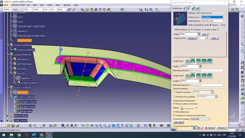
Then on the boundary of CLASS A SURFACE and regarding TOOLING AXIS I have constructed CLASS C SURFACE as shown.
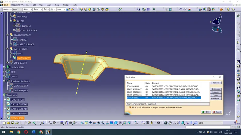
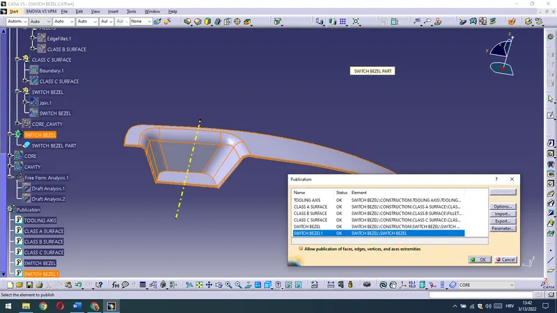
I have published all that Surfaces including closed surface SWITCH BEZEL.
Afterwards I have closed those Surfaces and made a solid part.
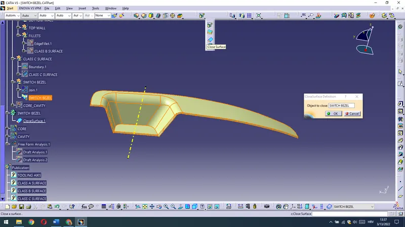
I have published closed Part also.
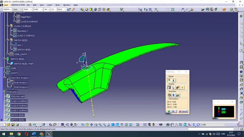
Now I am going to make a Draft Analysis on the Solid Part.So,as it can be seen all drafting angles are satisfactory and a part is manufacturable.
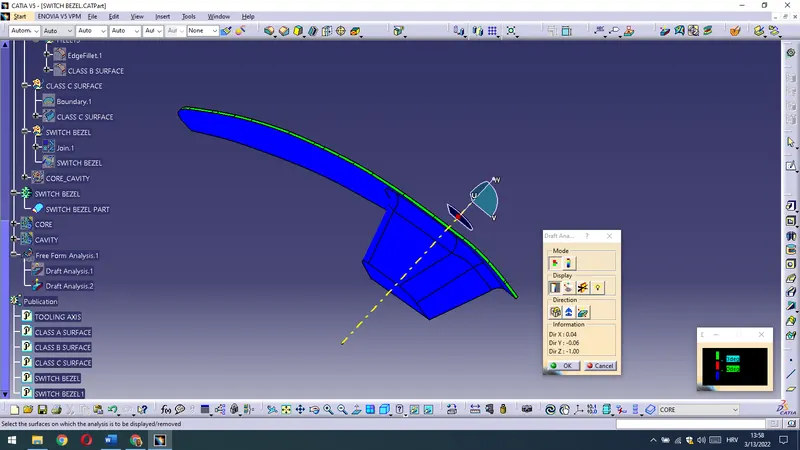
So,now is time to construct PARTING LINE and a PARTING SURFACE for a CORE and CAVITY design.Now I am showing finished part regarding CLASS A SURFACE , CLASS B SURFACE and CLASS C SURFACE.
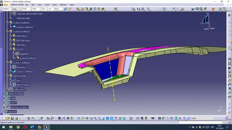
Then in order to get a Parting Surface (that is a Surface between Core and Cavity,where mold closes.It is a Surface of the most importance,because it is done on the basis of the designed surface (CLASS A SURFACE) and on that basis is defined Tooling Axis,Class B Surface and a Class C Surface.Now regarding all that mentioned, Parting Surface should be defined.Parting Surface must be done with great attention and very carfelly examined when finished to avoid possible leaks in the mold,inproper closing etc.
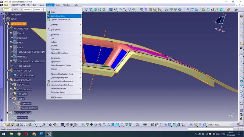
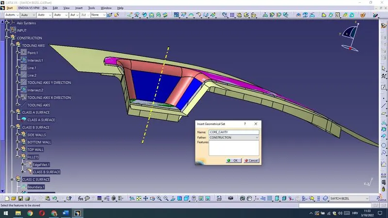
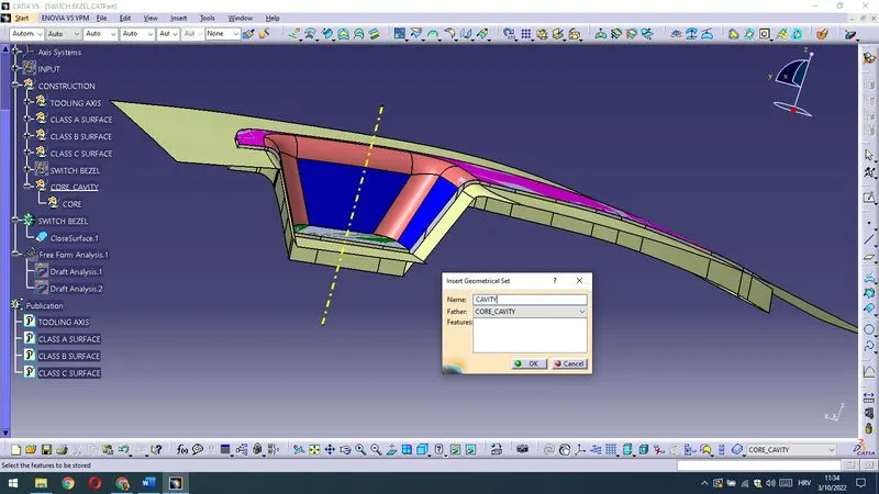
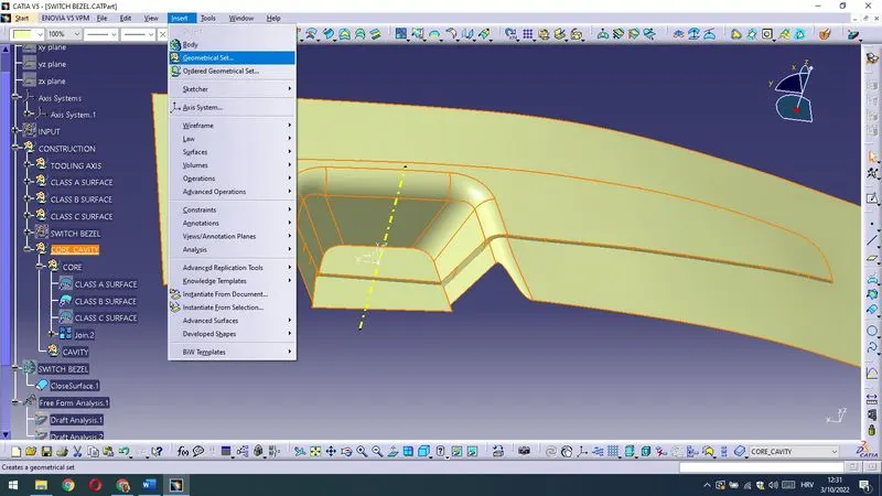
So,at first I am inserting new Geometrical Set called CORE_CAVITY and under it Geometrical Sets CORE and CAVITY.
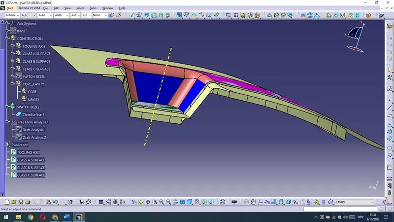
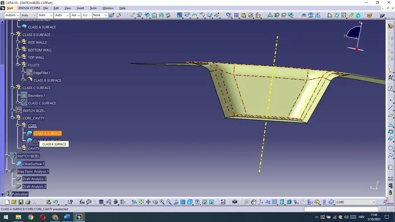
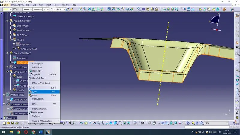
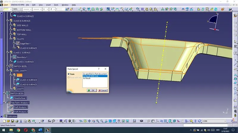
Then under the CORE I will Copy-Paste with Link CLASS A SURFACE,CLASS B SURFACE and a CLASS C SURFACE.
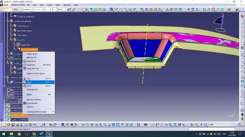
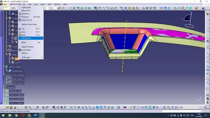
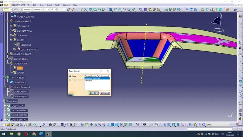
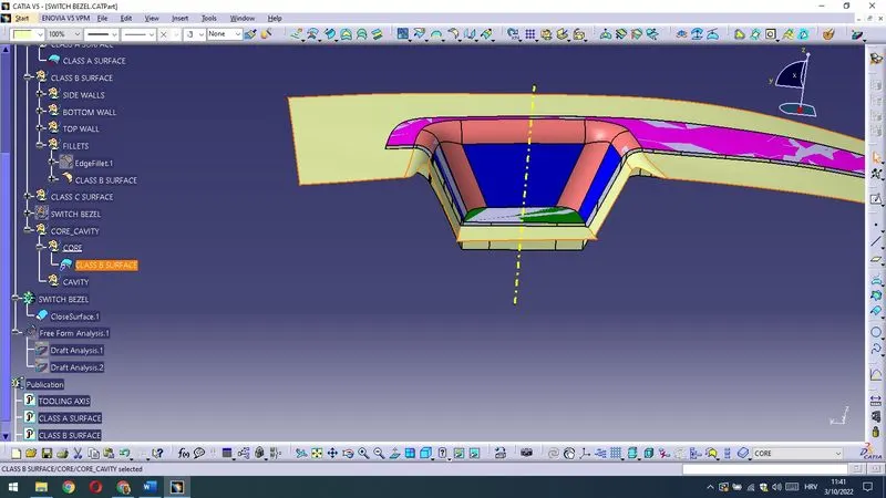
After CLASS B SURFACE ,the same procedure for a CLASS A SURFACE and I have reordered the children.
Then the same for a CLASS C SURFACE.
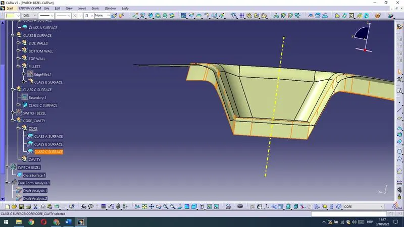
When I look normal on the TOOLING AXIS from Top I see image as shown bellow (I have changed colour of the CLASS C SURFACE to have a better overview).
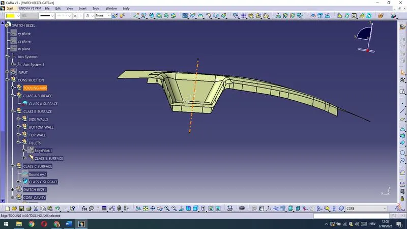
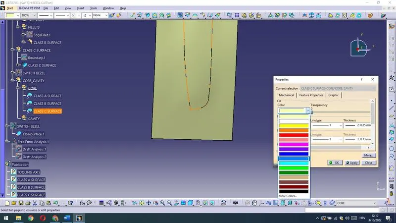
So Top view regarding TOOLING AXIS shows.

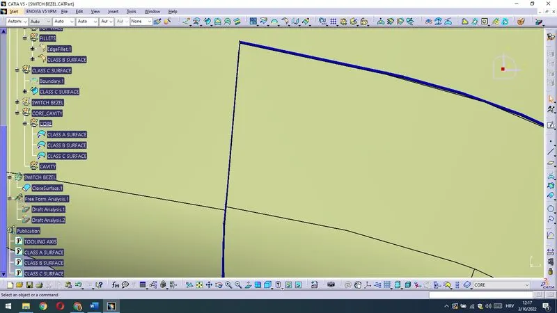
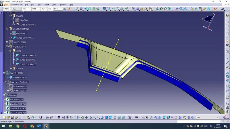
I am going back to check a model with Draft Analysis once again,it shows
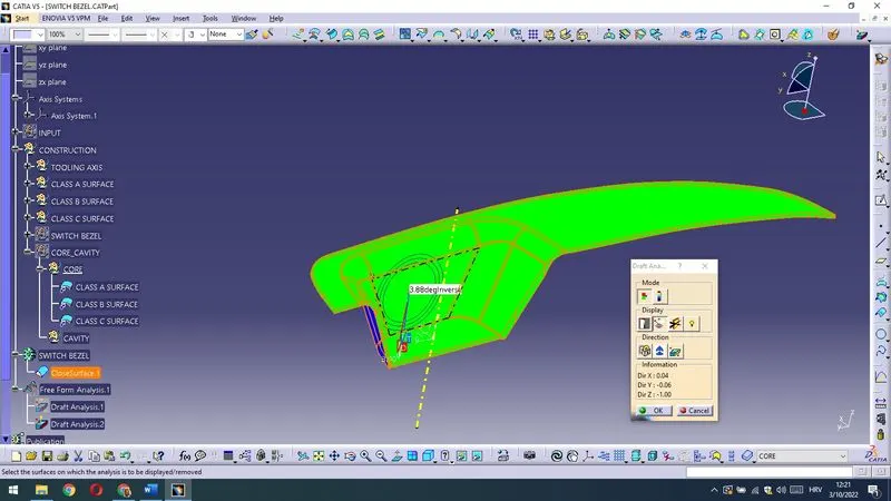
So,the blue CLASS C SURFACE from Top View is to see,that means CLASS C SURFACE is good constructed,Drafts are with more than 3deg done and now we can design Parting Surface on that basis.
Now I am joining CLASS A SURFACE with a CLASS C SURFACE and that I am trimming with a CLASS B SURFACE as shown bellow.
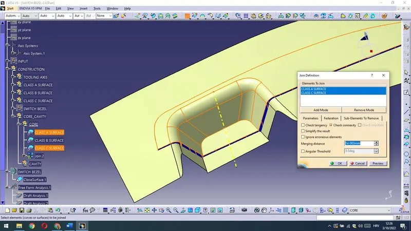
So,here under CORE_CAVITY I will insert new Geometrical Set called PARTING SURFACE_PARTING LINE and there I splited those Surfaces.
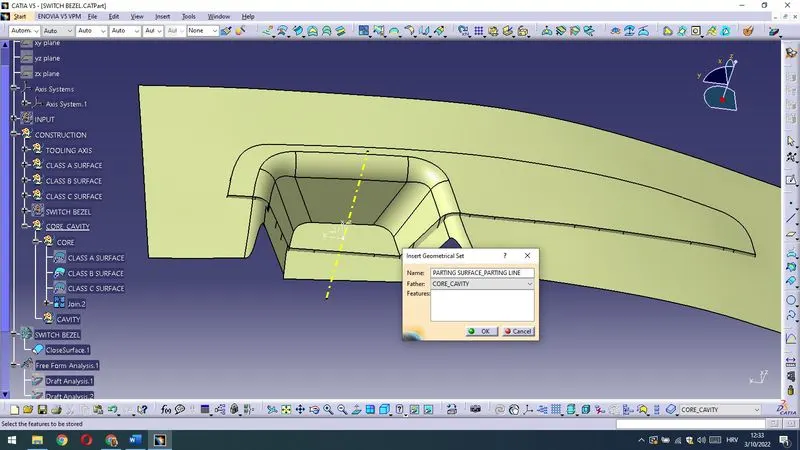
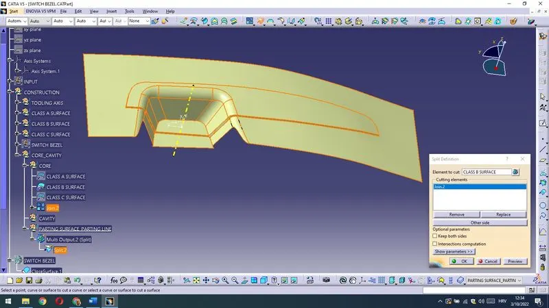
So,there I got required PARTING SURFACE (I will rename the Split.2 as a PARTING SURFACE and change the colour of it).
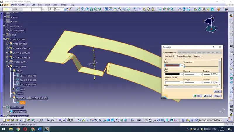
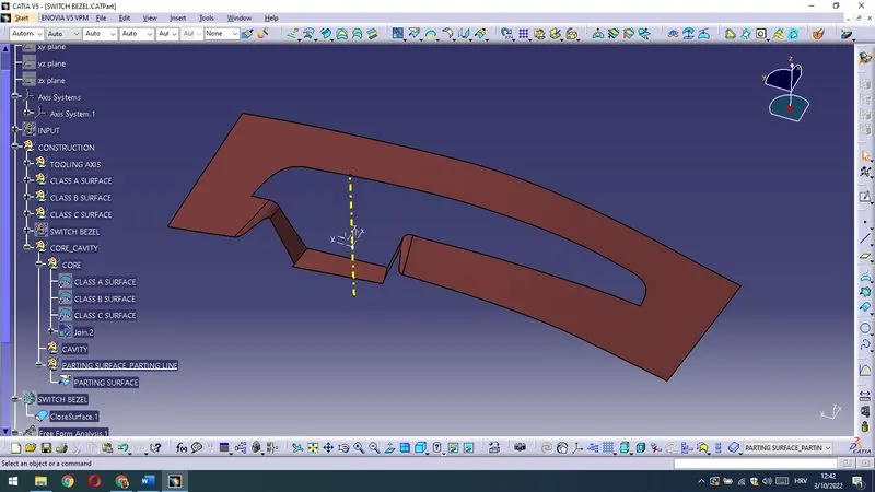
And there where PARTING SURFACE intersects on the part SWITCH BEZEL I get a PARTING LINE.
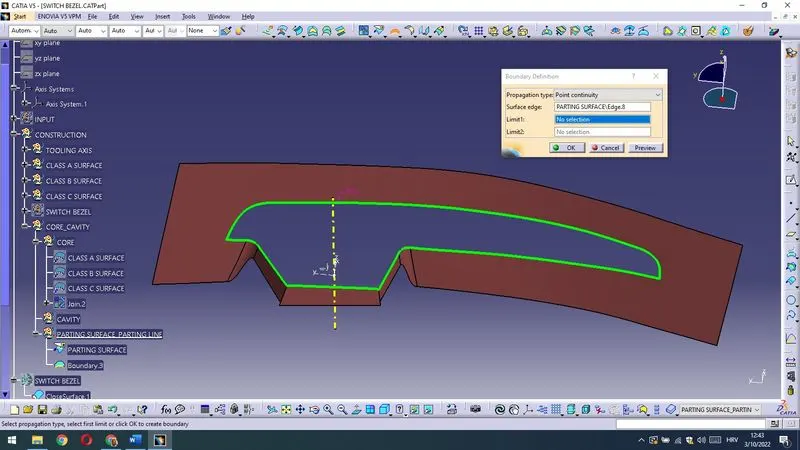
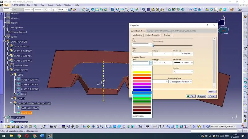
Then I am renaming and changing the properties of the Boundary.3 .
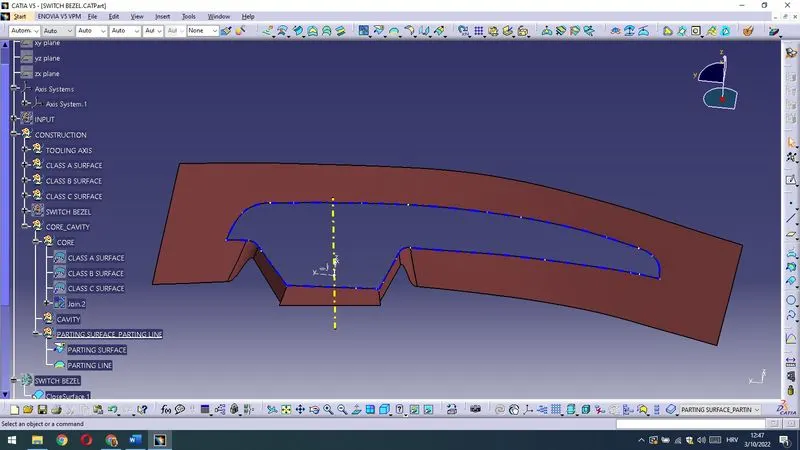
Finally I got PARTING SURFACE and PARTING LINE as shown bellow.
Now I am going to make CORE and CAVITY for a given part.
CORE
In the plane normal to TOOLING AXIS I am making a sketch and extrude it.
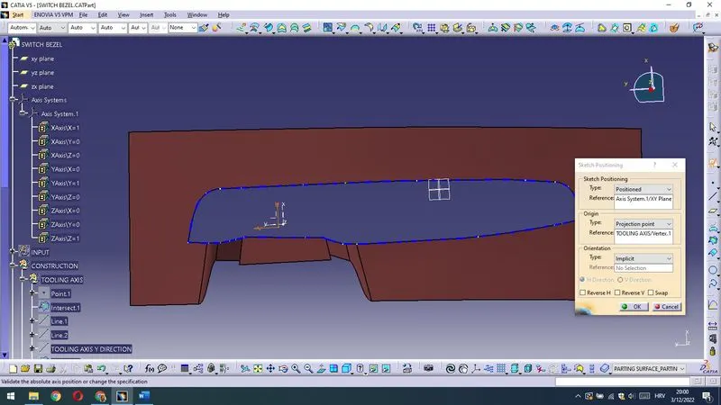
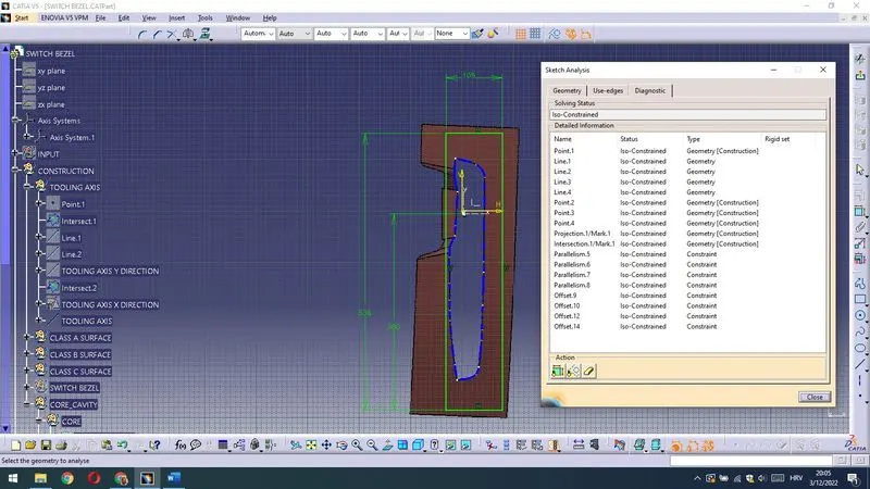
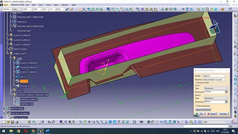
Then I have isolate CLASS A SURFACE, CLASS B SURFACE and CLASS C SURFACE and Trimed Surfaces as shown bellow.
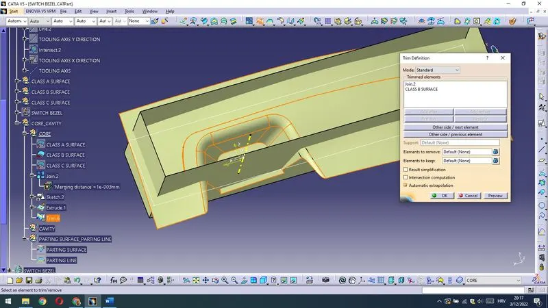
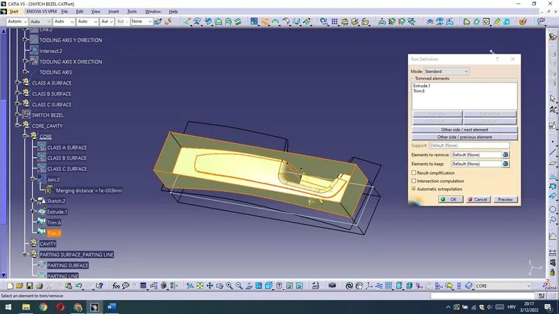
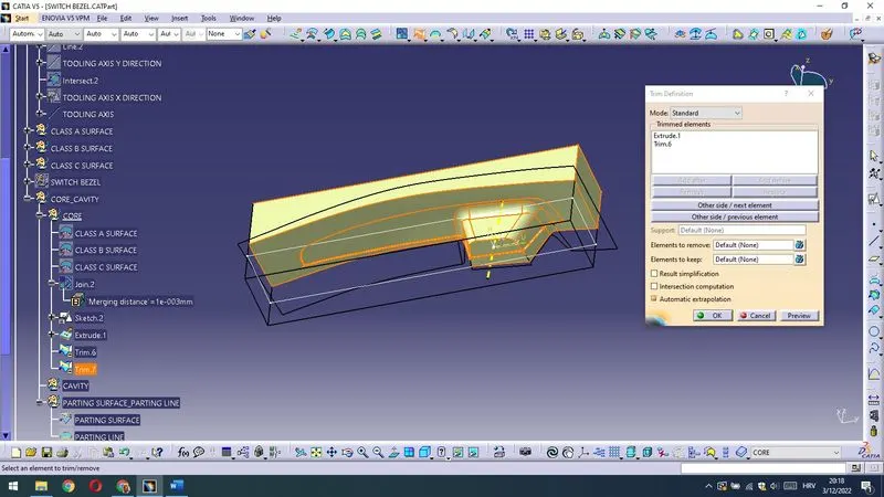
Now I am going to fill surfaces and close it to get a Solid Part called CORE.
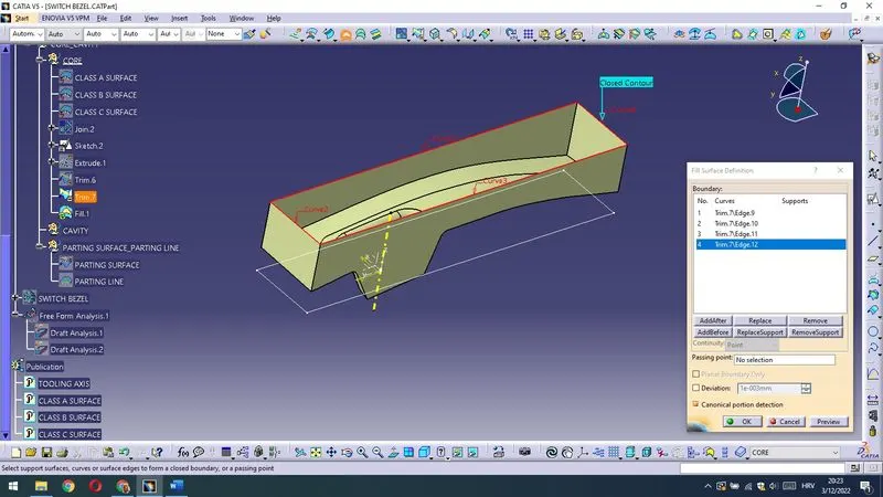
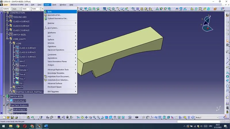
I have inserted New Body where I will have closed CORE as a Solid Part.
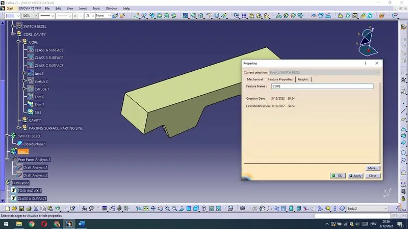
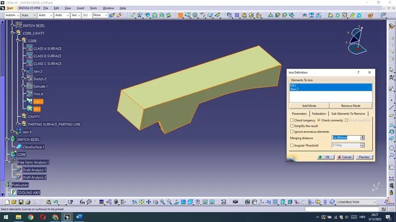
Then I have closed the Surfaces.
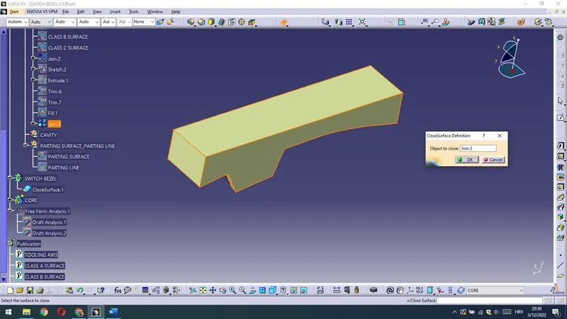
I have closed Surfaces and get my CORE Part.I have changed properties of the CORE.
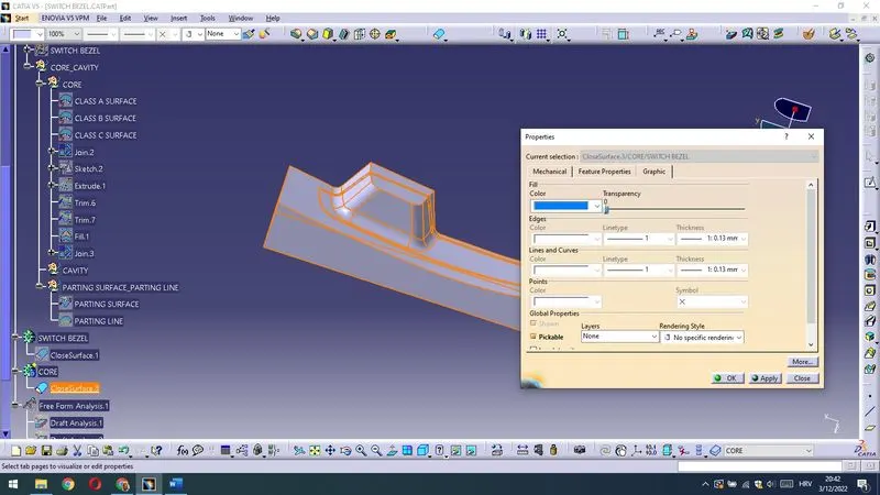
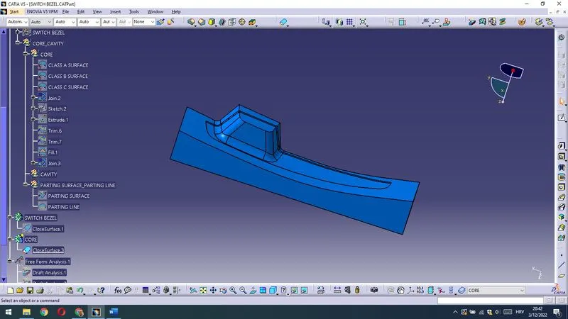
Now I will do the same procedure for a CAVITY.I wiil Copy-Paste Surfaces as follows.
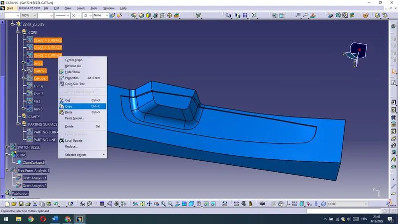
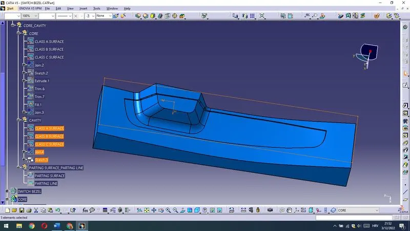
Then Extrude and Trim as follows.
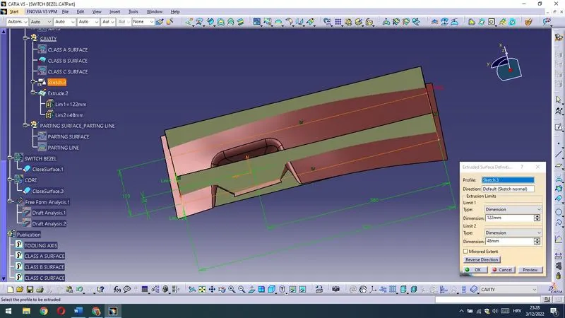
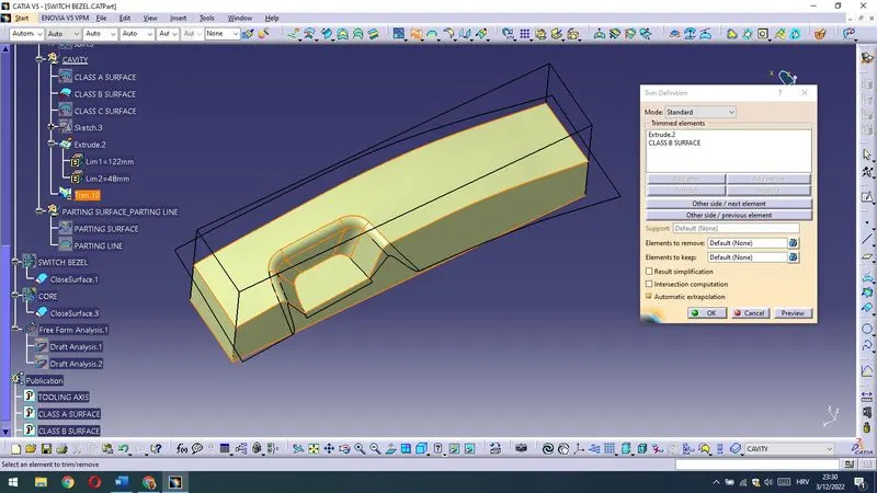
Now comes fill.
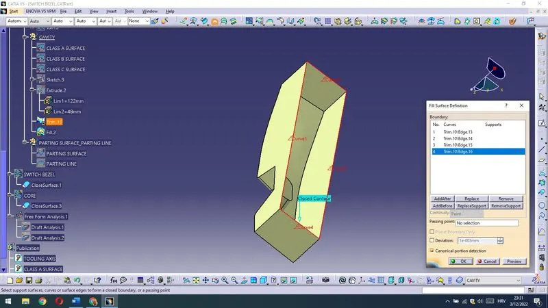
Then I am inserting New Body with a name CAVITY where I will close those Surfaces.
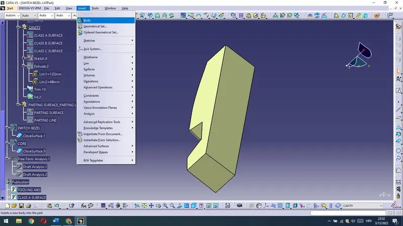
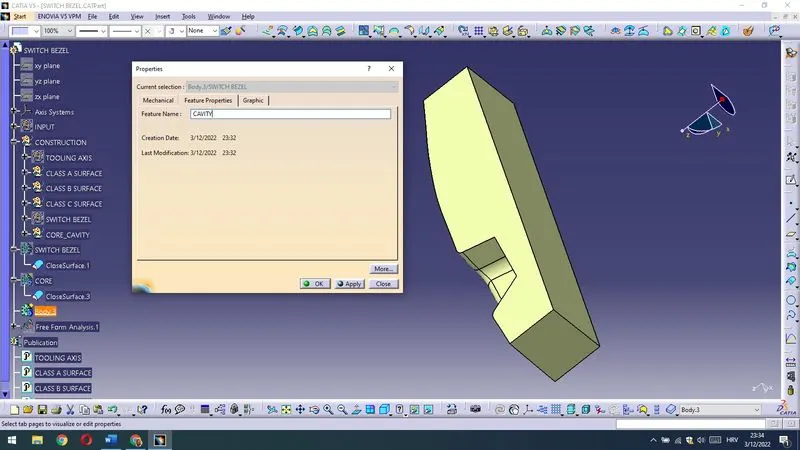
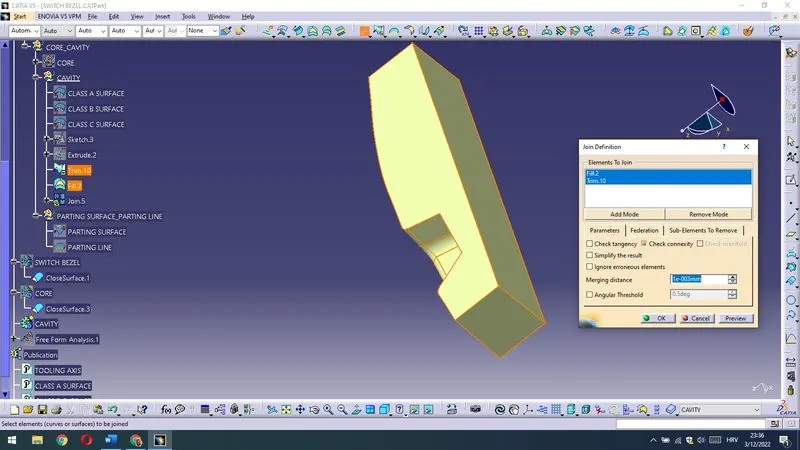
Now comes join.
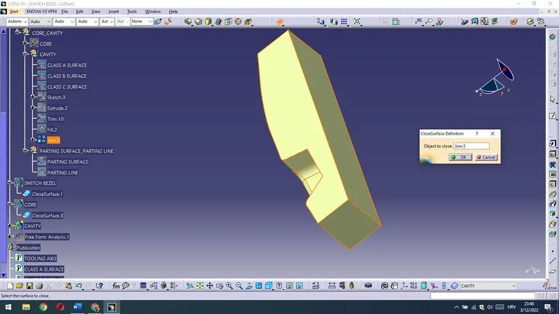
And I am closing CAVITY surface.
Then I will change the colour of the CAVITY part.
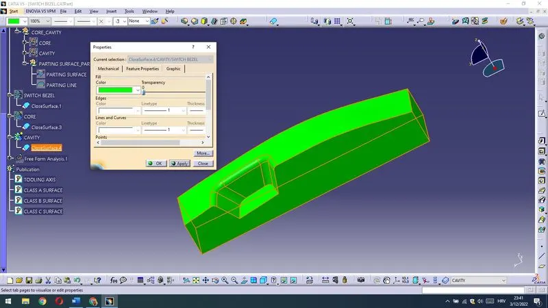
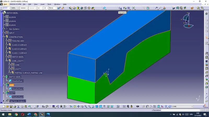
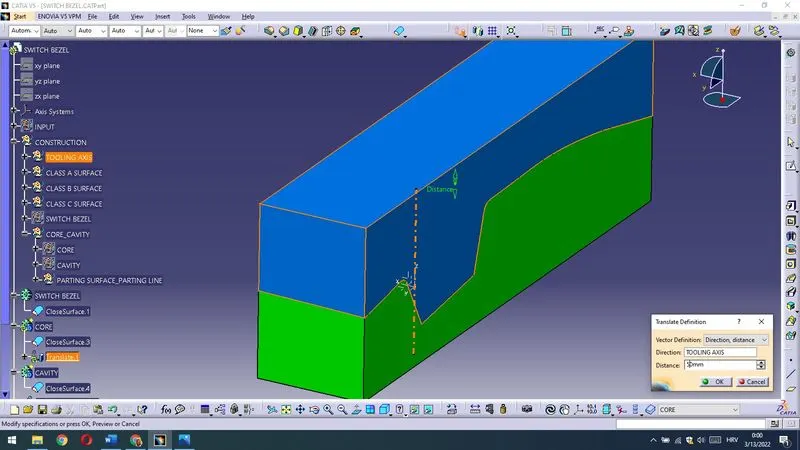
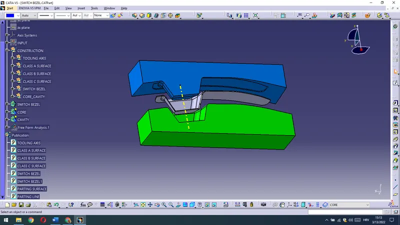
Now I have got CORE,CAVITY and a Part SWITCH BEZEL in between.
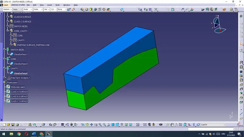
I will show those parts in correlation to get a overview of the parts.
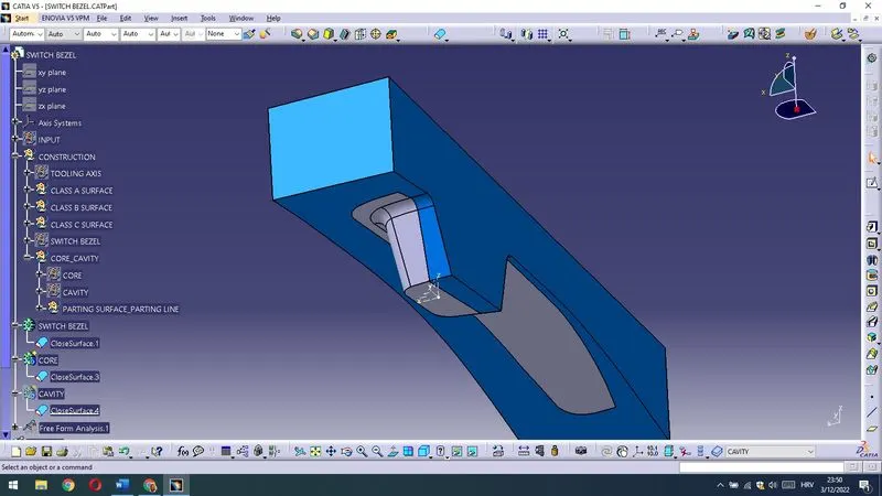
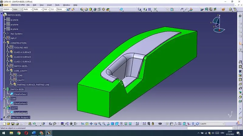
And translation view shows.
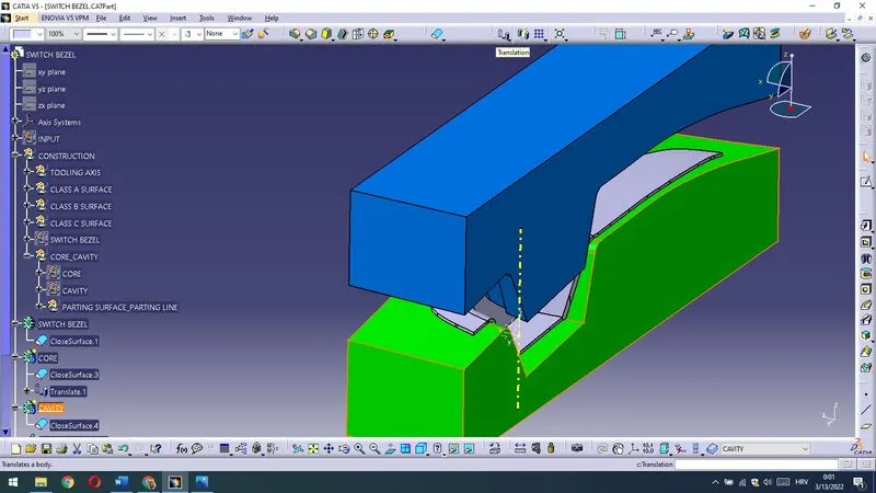
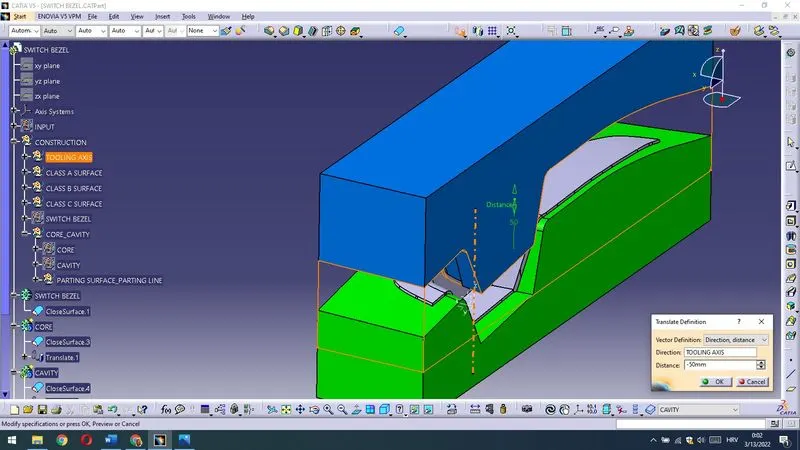
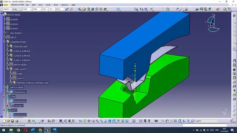
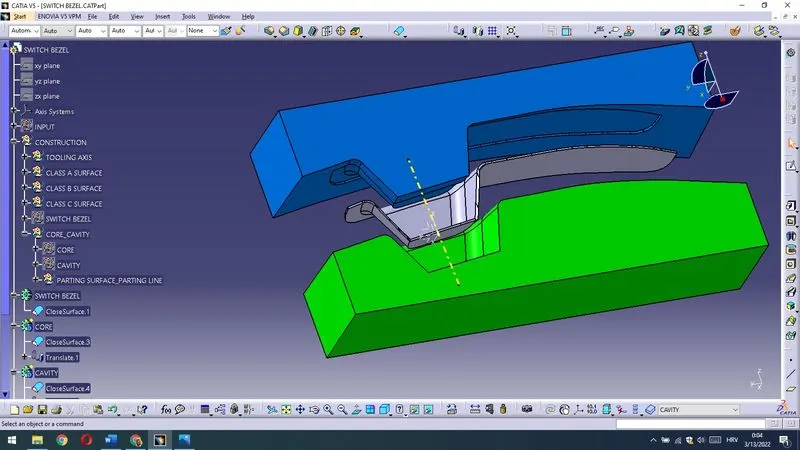
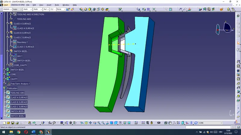
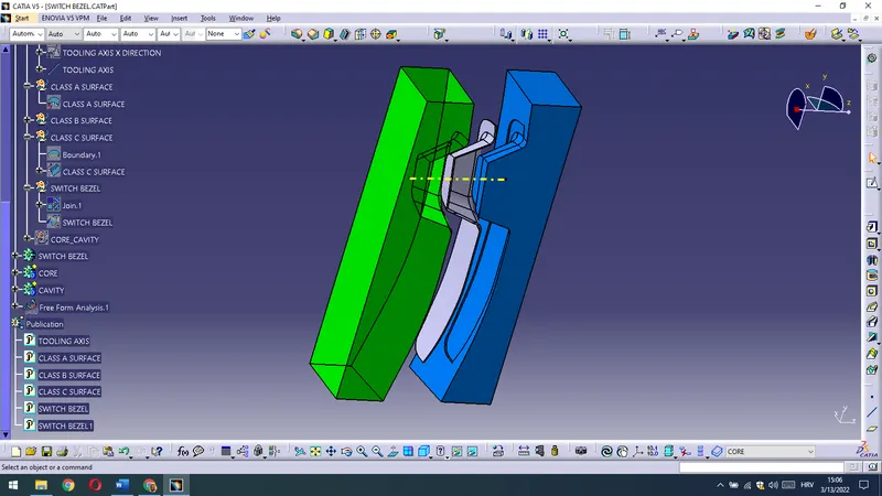
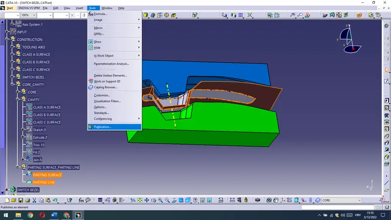
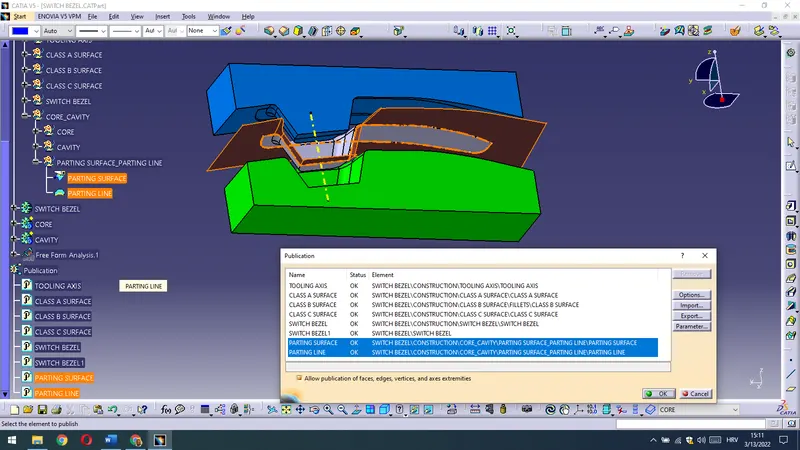
After I have shown parts in various views,where one can see those parts in correlation I am on the end publishing PARTING LINE and PARTING SURFACE.
So,that will be all fellows.
Best regards,
Ivan Tole