Week 8 - Challenge 2 - Base Bracket Design
Hi colleagues,
summaries of the requested tasks are given bellow.
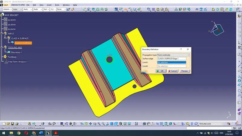
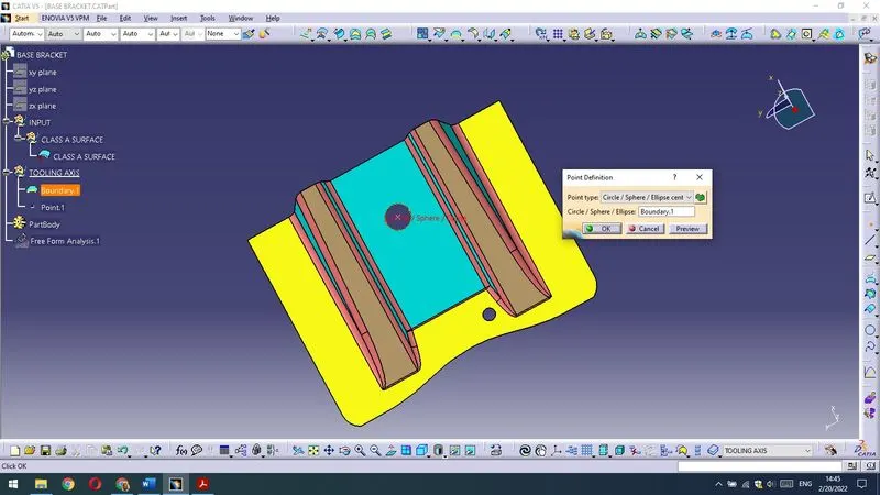
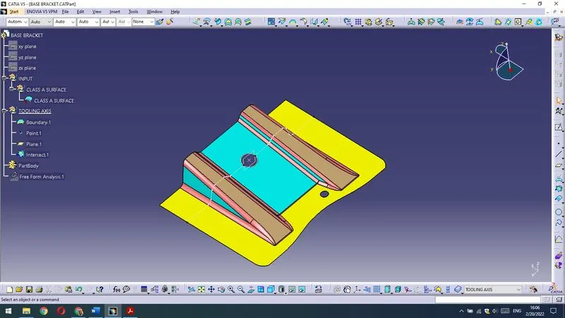
After I have opened a Part,on the Input base I have seen Class A Surface,on which I should first determine tooling axis.On the part is couple of drafts and a two hole given.After considering drafts and holes and possible part extraction for core/cavity I have bigger circle taken as a basis for constructing tooling axis.So,at first I have extracted circle boundary and have given point in the circle middle to have a basis to draw a plane in that point parallel to YZ plane – that determines TOOLING AXIS Y DIRECTION.I have inserted new Geometrical Set.
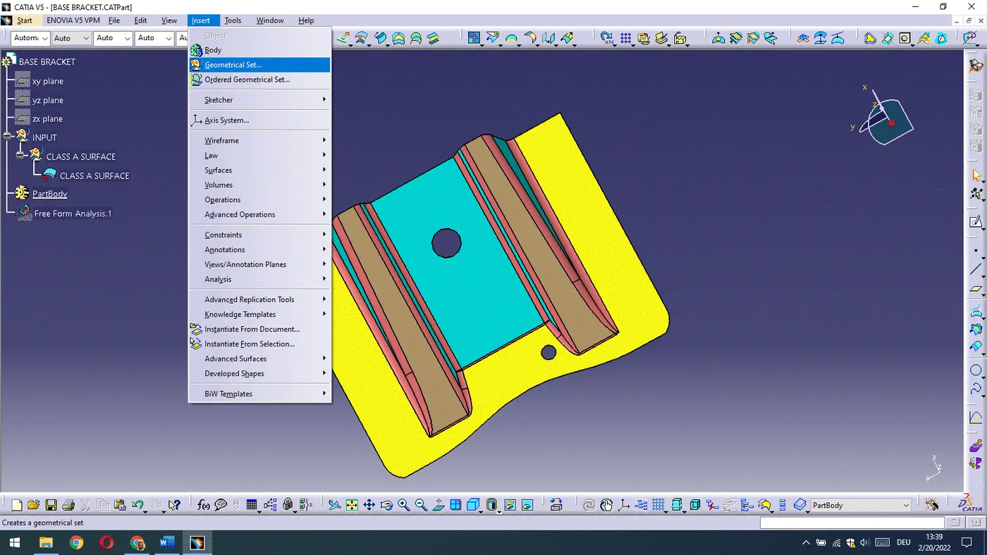
And renamed it as TOOLING AXIS.
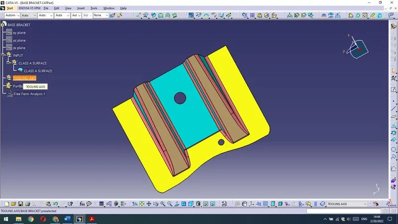
As I have decided to make a TOOLING AXIS on a bigger circle I have drawn a boundary,circle and a plane on it as it is shown bellow.
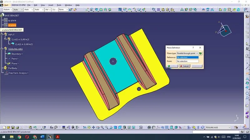
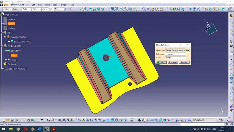
Afterwards I have intersected Class A Surface with a plane to get intersection profile,on which I can draw lines for construction Tooling axis with the bisecting option.
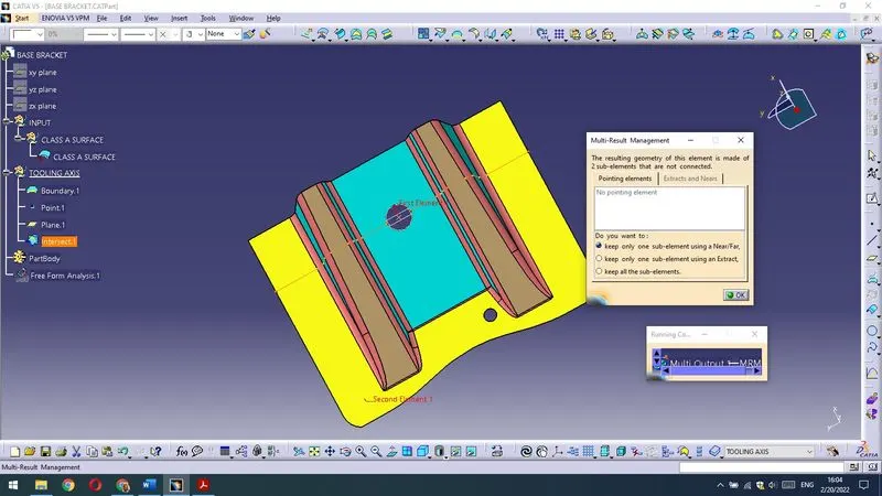
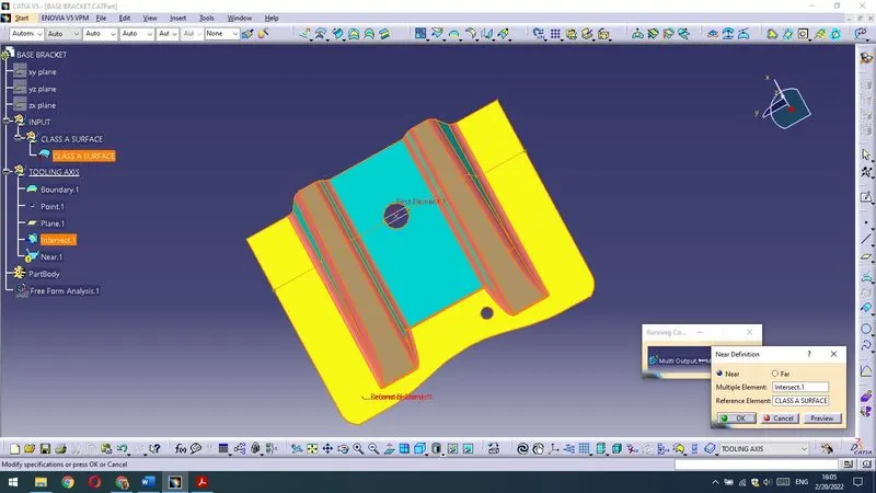
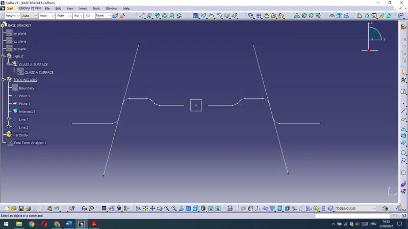
Now I am constructing lines on draft intersection to get a Tooling axis in Y direction.
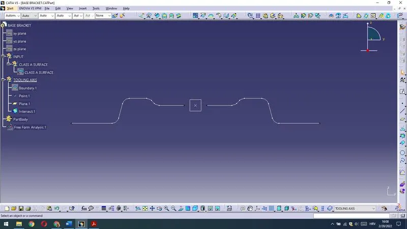
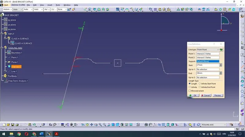
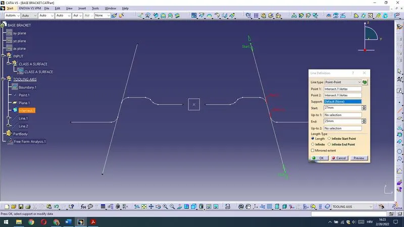
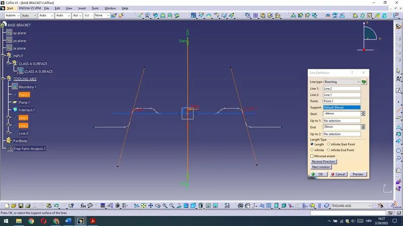
Then,I have made bisecting line between those lines as the first dummy line for Tool axis.
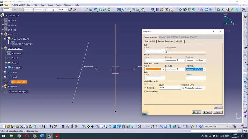
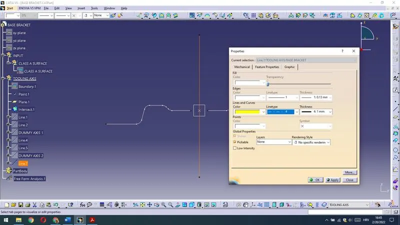
I had rename it as a DUMMY AXIS 1 and changed properties.
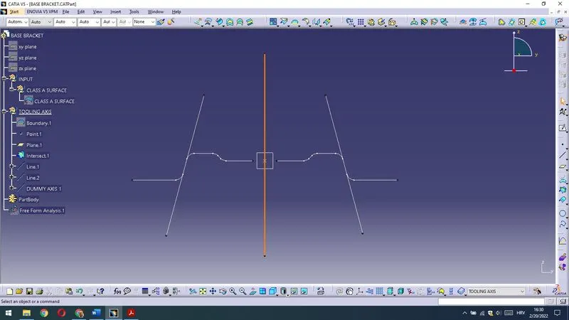
Then I have done the same procedure for a second drafting lines to have a second dummy line in Y direction.
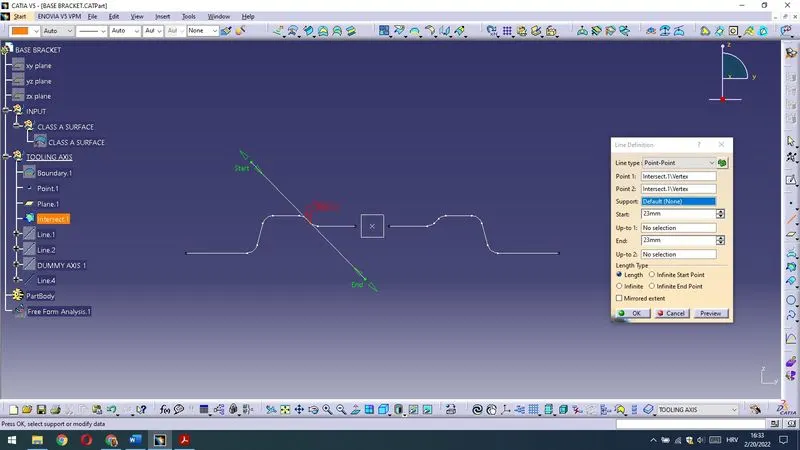
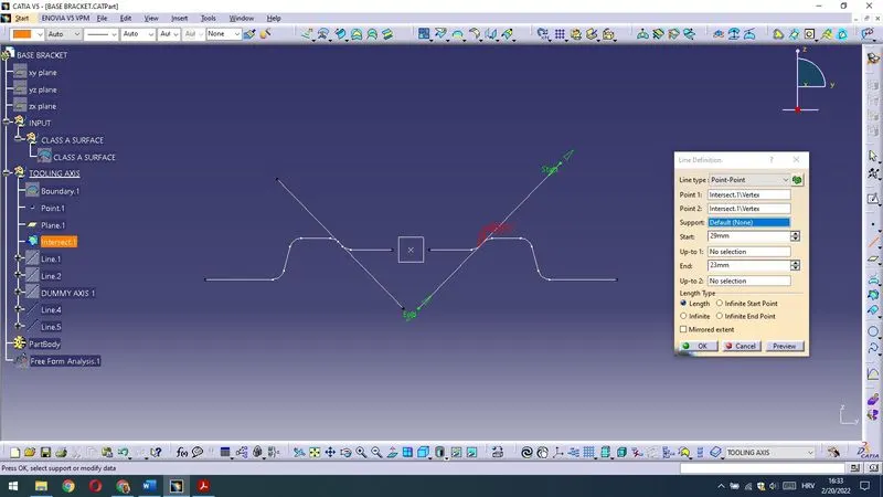
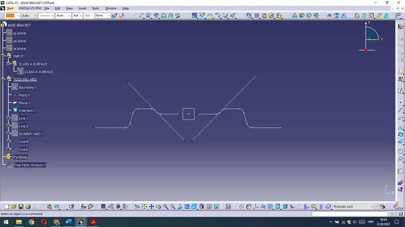
Then I have done bisecting that 2 lines in given point to get a second bisecting line for DUMMY AXIS 2 in Y direction.
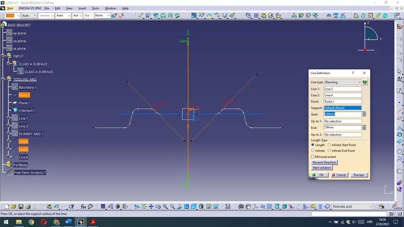
I changed the properties and rename it as DUMMY AXIS 2.
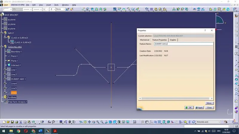
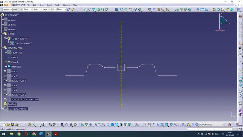
Finally I made a bisecting line between DUMMY AXIS 1 and DUMMY AXIS 2 to get a TOOLING AXIS Y DIRECTION.
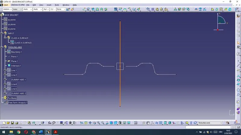
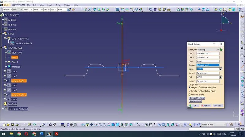
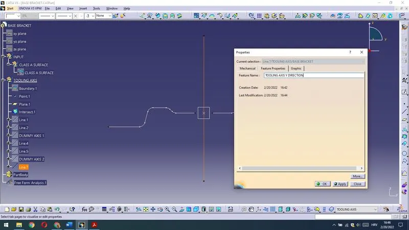
I have changed a properties of the consructed bisected line and renamed it as TOOLING AXIS Y DIRECTION.
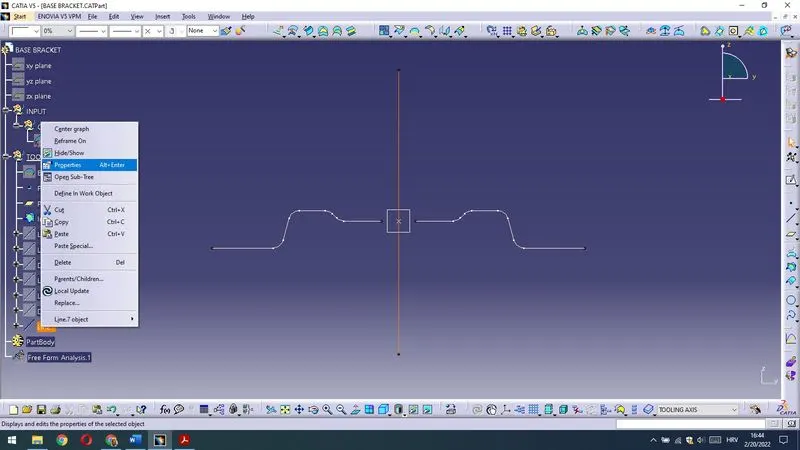
Afterwards I will do the same procedure for Tooling axis in X direction.
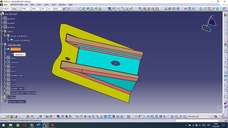
Draw plane in the point paralel to XZ plane.
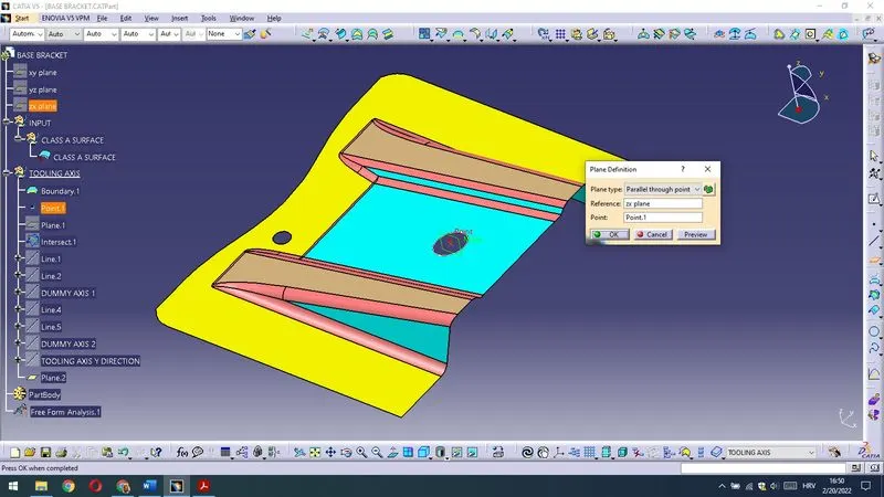
Then intersect CLASS A SURFACE with a constructed plane to have a intersection in that direction.
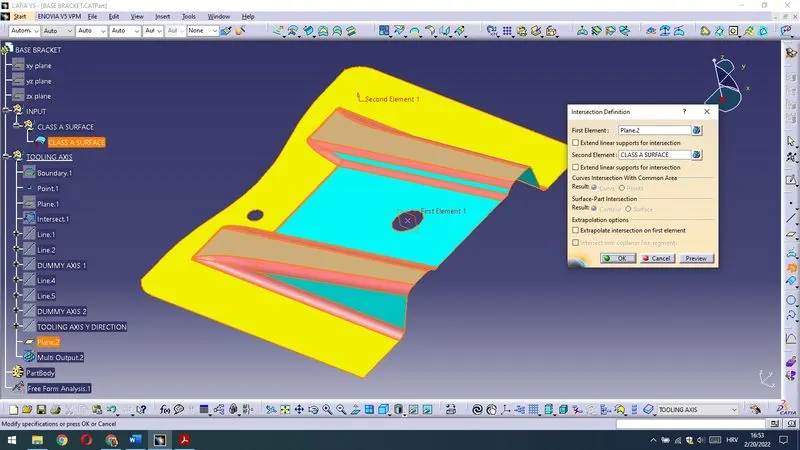
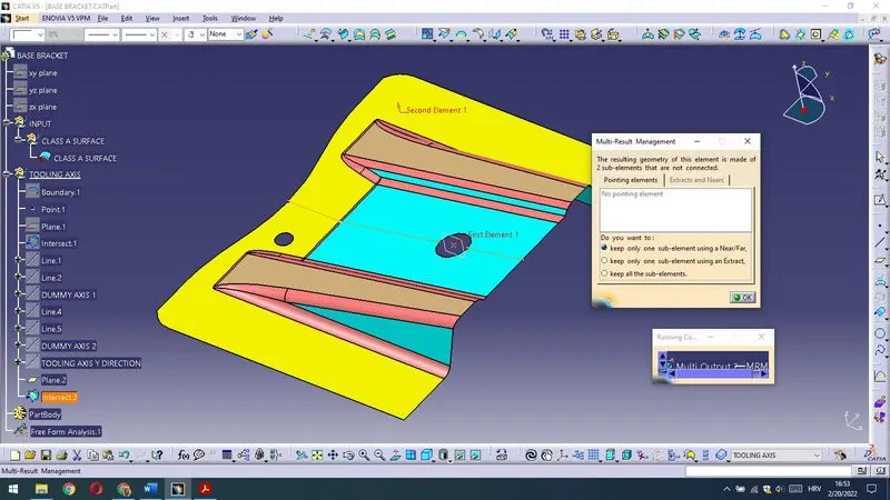
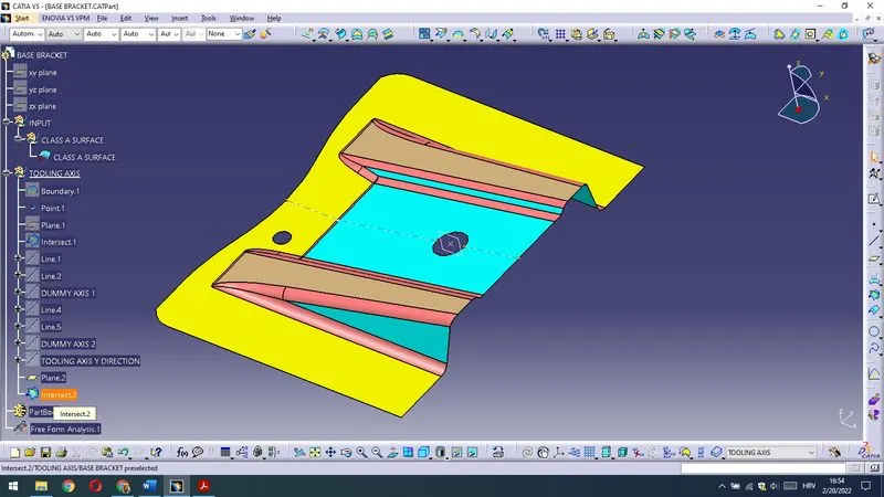
Here is specific – there are no drafts,only surface under the angle – that is why I want to determine angle between that surface where the big circle is and Z axis (as a result of 90deg on yellow surface).
With the options customize I will thick and the Angle field.
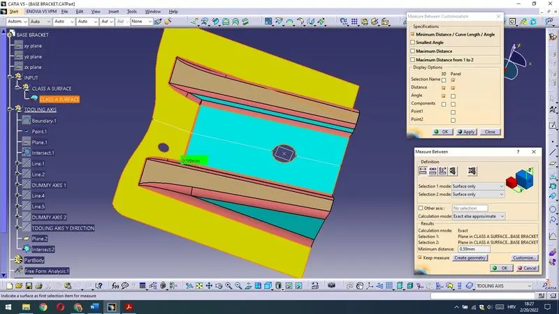
Then I will measure it.
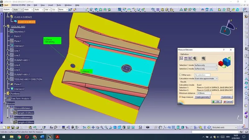
It shows 168,64deg – that means Z axis and the intersect line are under 78,64deg.
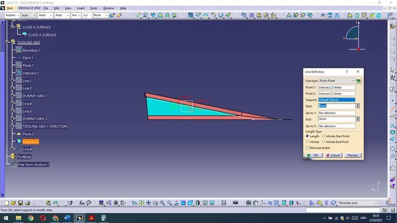
After we have drawn a line between vertices I am drawing a line under 78.64deg regarding intersect line.At first I am inserting Axis coordinate system in the point.
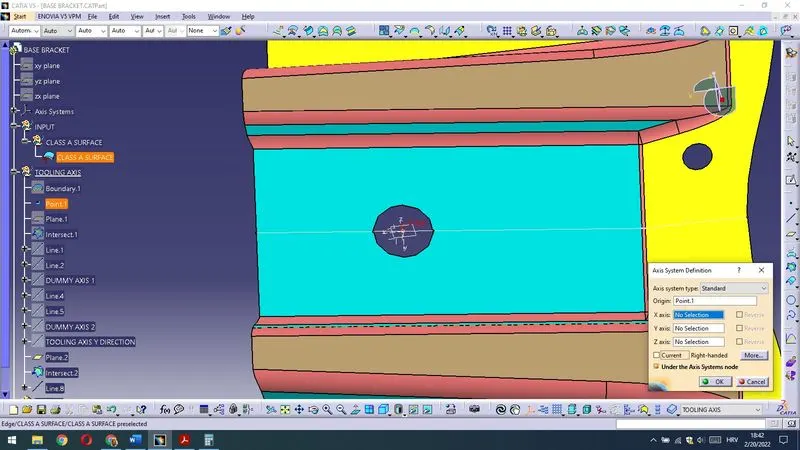
Then I am rotating axis system around Y axis for a - 11.36deg (90deg-78.64deg).
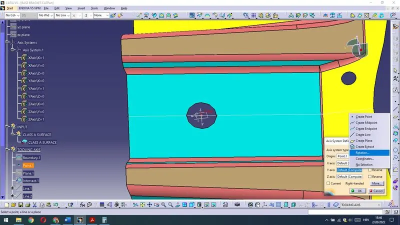
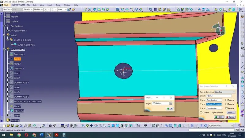
So,I gett axis system with z axis perpendicular to green big surface and a circle.
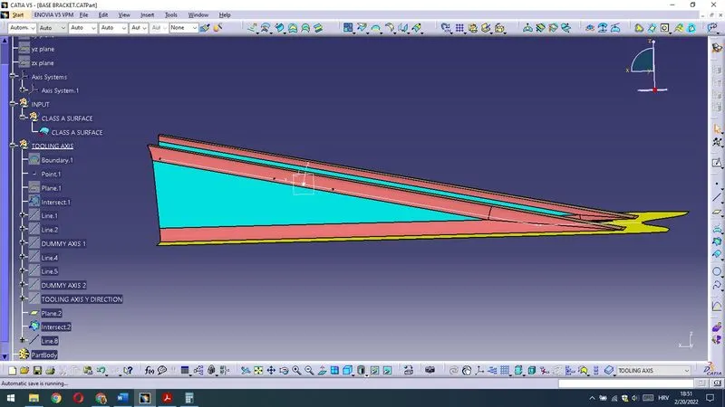
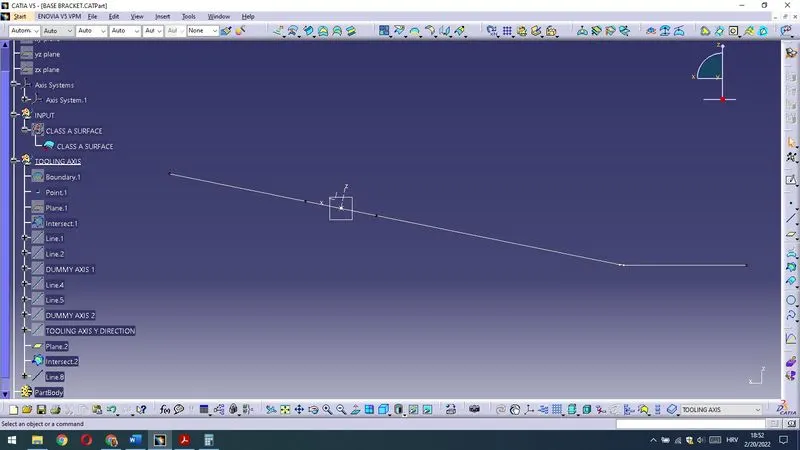
There I have drawn a TOOL AXIS LINE X DIRECTION in z direction perpendicular on intersection lines on big circle.
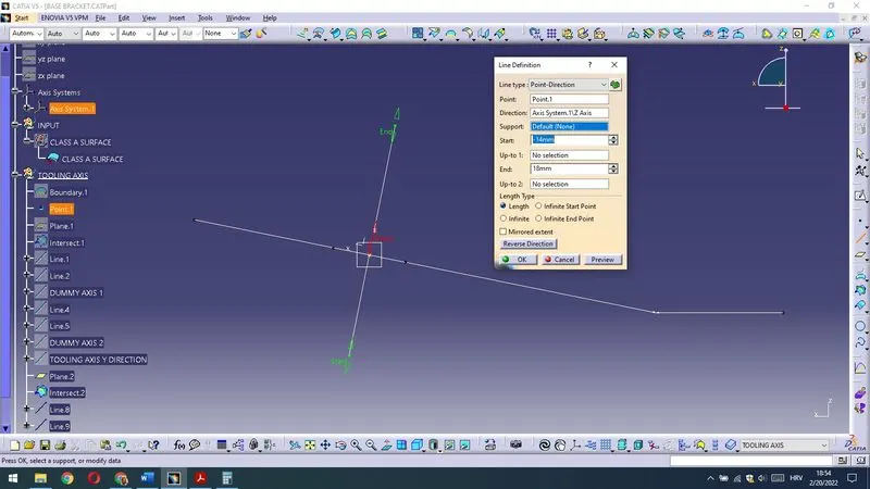
I changed the properties of the line and rename it as a TOOL AXIS LINE X DIRECTION.
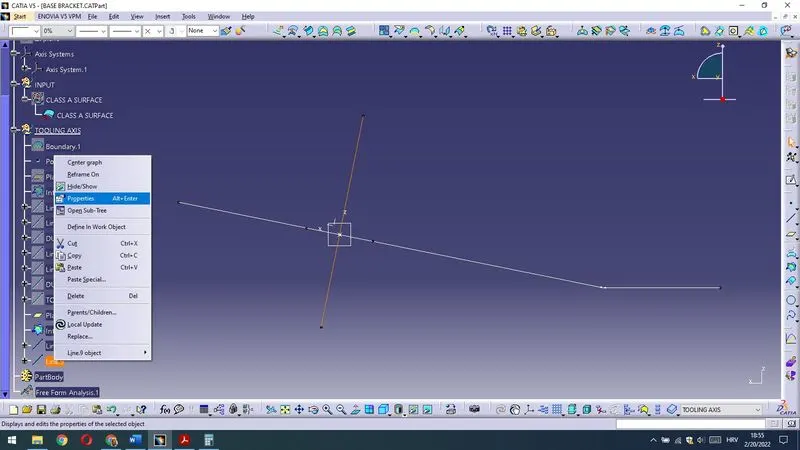
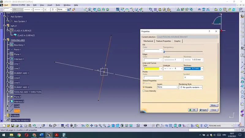
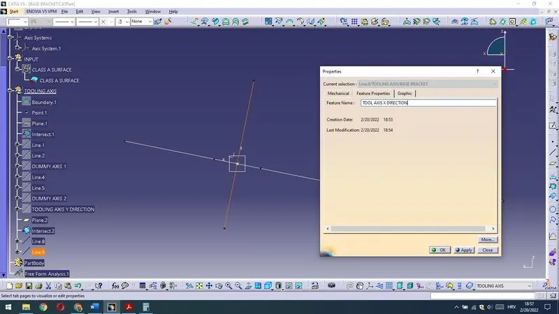
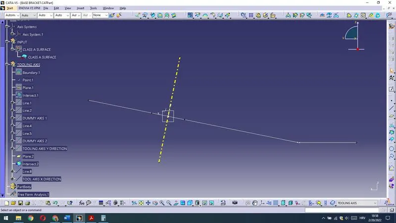
At the end to get a TOOL AXIS line I will do bisecting TOOL AXIS X DIRECTION and TOOL AXIS Y DIRECTION.
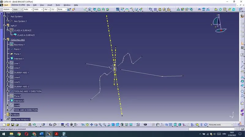
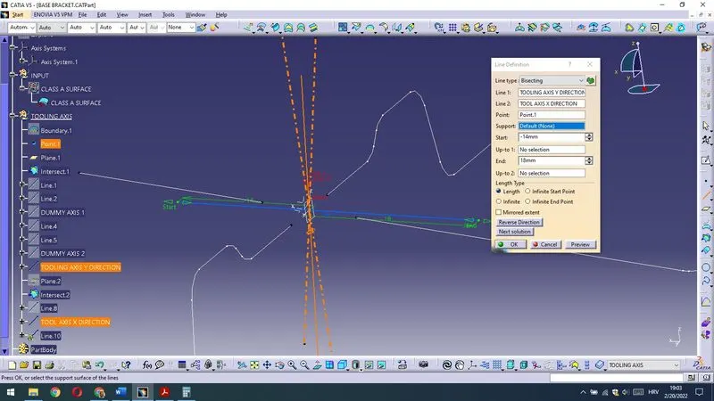
If we get unsatisfactory solution for bisecting we should click Next Solution option till we get a orientation as on picture.I am then renamed a line as TOOLING AXIS and changed properties.
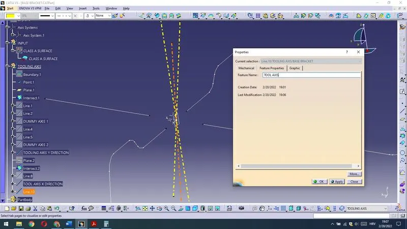
I have constructed TOOL AXIS for a given Part.
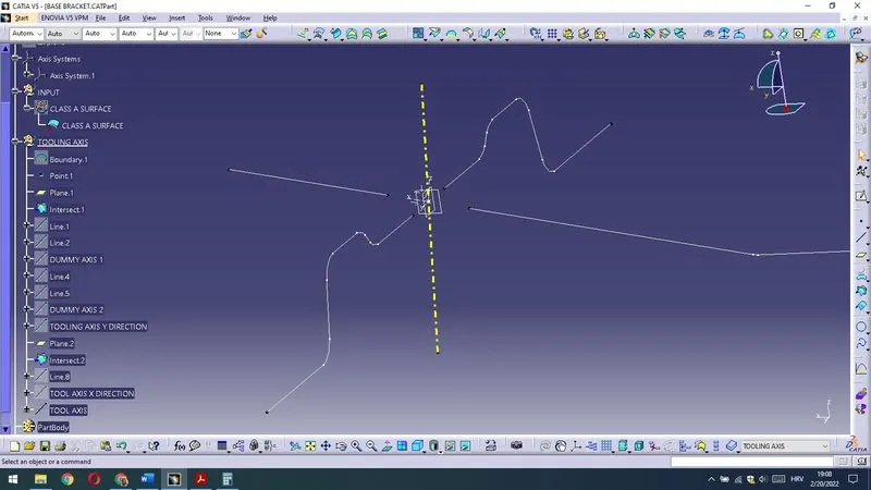
Now I will Copy and Paste CLASS A SURFACE from the INPUT as a separate Geometrical and reorder children to get Proper Structure tree.I will Publish it and Publish also TOOL AXIS.
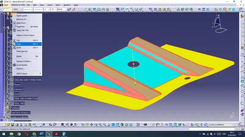
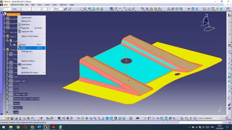
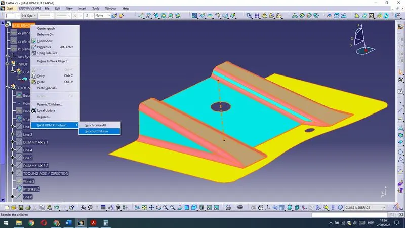
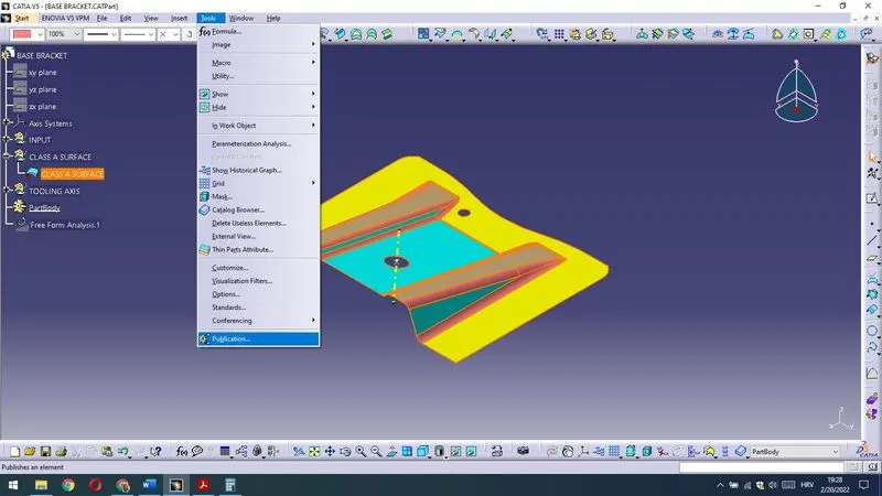
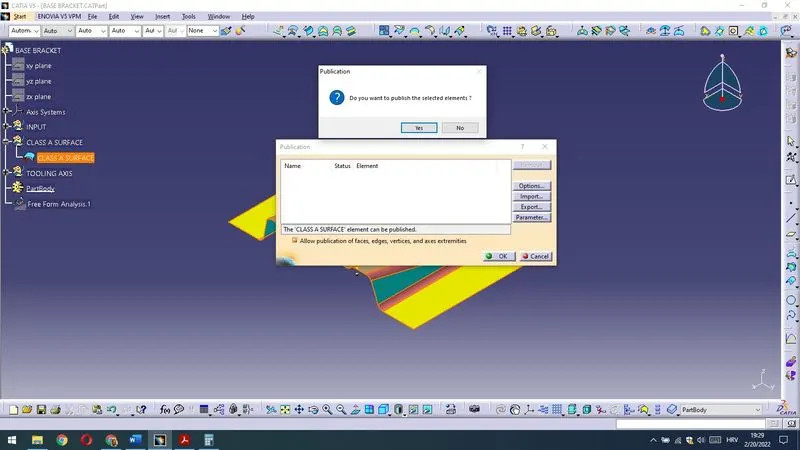
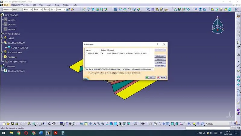
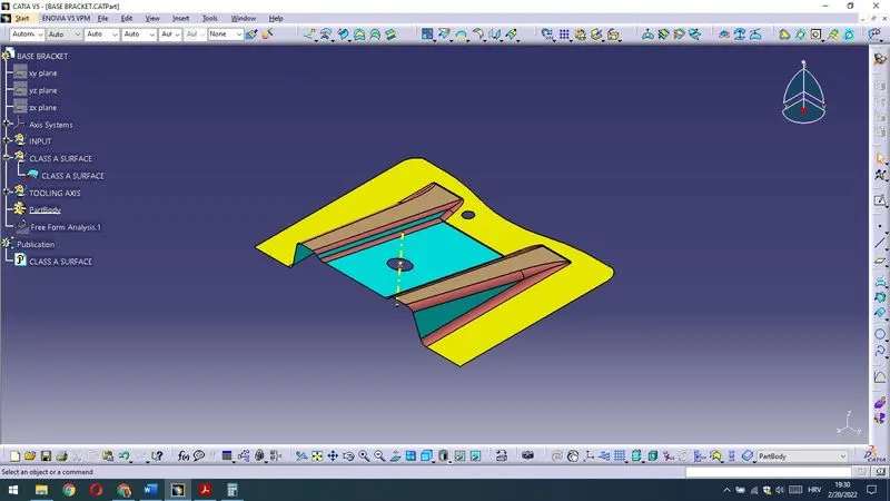
Then I have Published TOOL AXIS.
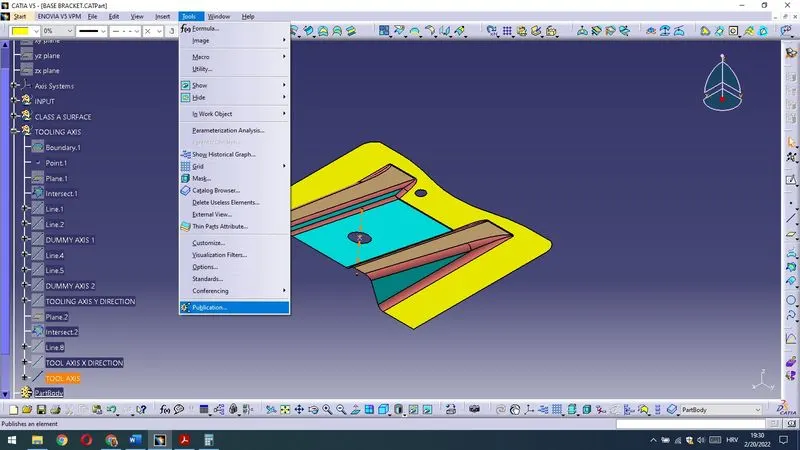
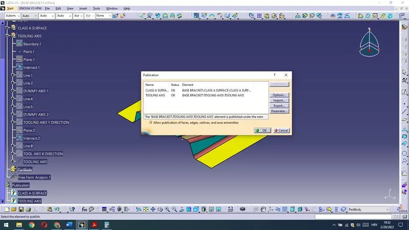
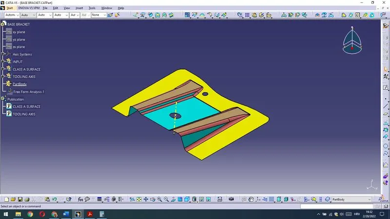
I have then conducted Draft Analysis on the constructed TOOLING AXIS.Checked the first View Mode Customization – Material is applied,that means I could go further in doing Draft Analysis.
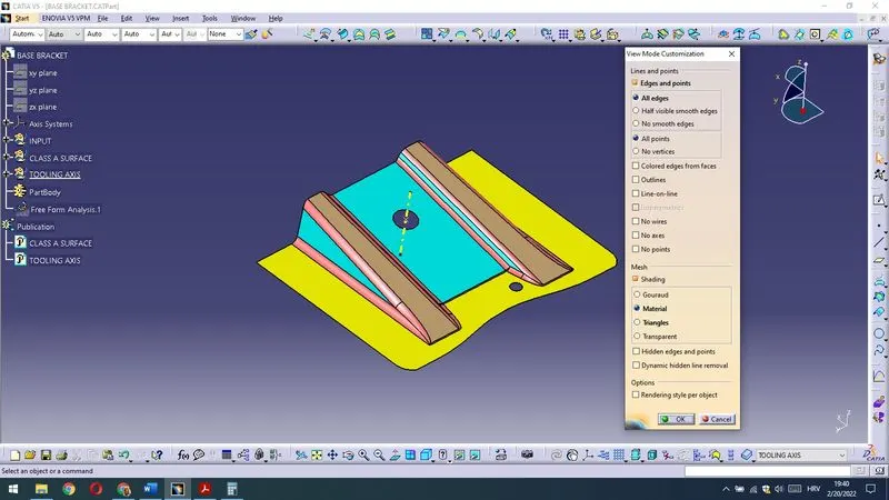
I have get Feature Draft Analysis ,click on the Compass in Direction section and I have moved the Compass on the TOOLING AXIS as it is shown on the images bellow.
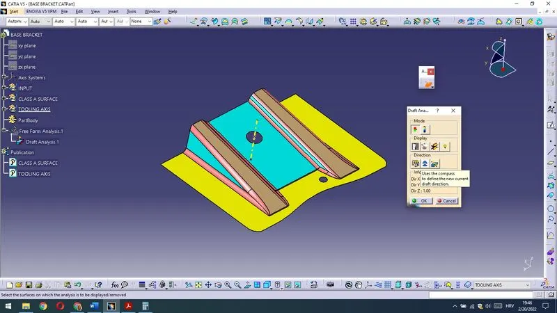
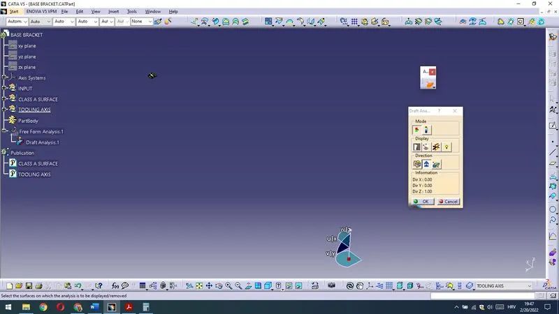
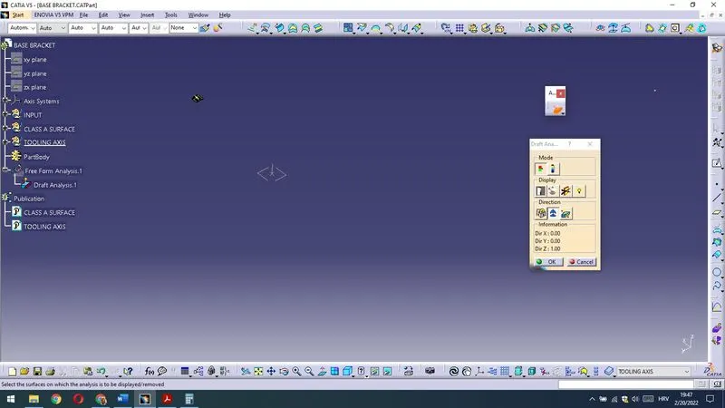
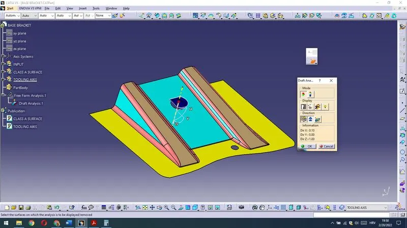
Then I locked the Compass (we can allways flip draft direction with the field rigth of compass icon).
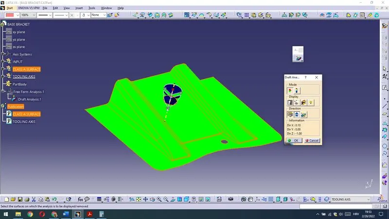
So – all Surfaces are green,drafting angle is more than 3deg – TOOLING AXIS is good determined.It is manufacturable.
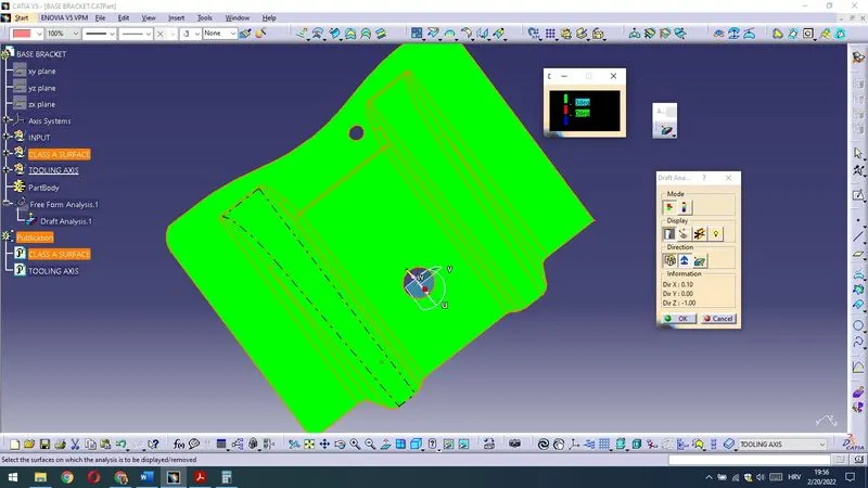
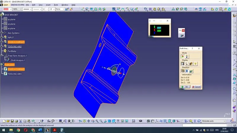
Flip direction – all is blue – the Part is eitherway good for production.
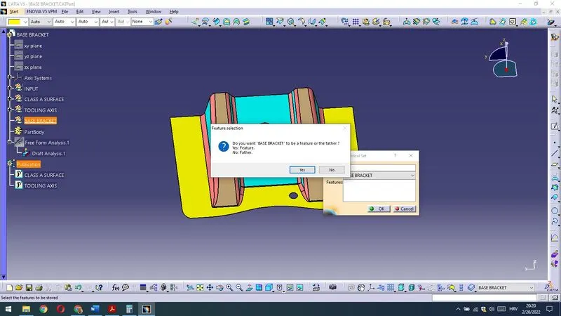
Now I am going to design CLASS B SURFACE so called Engineering Surface,part thicknes should be taken in consideration.I will create new Geometrical Set called BASE BRACKET.
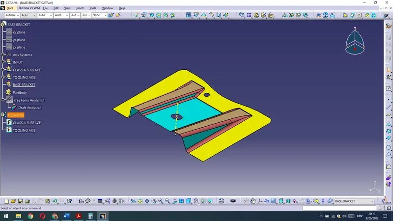
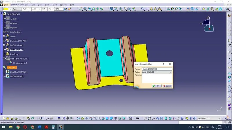
In the Geometrical Set BASE BRACKET I will Insert one more Geometrical Set and name it as CLASS B SURFACE.
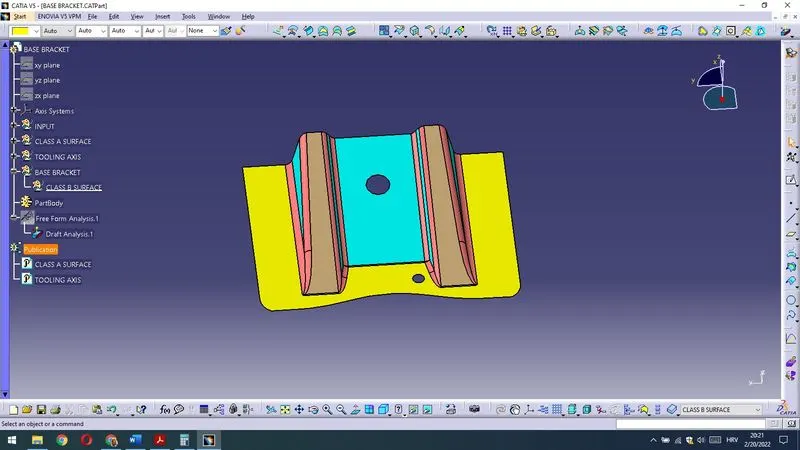
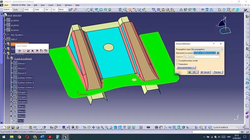
Thickness of the part is 2,5mm – that means I will offset all plain surfaces for a thickness value (without fillets,sometimes that is troublesome for offsetting).So I am extracting plain surfaces (with no propagation) in the CLASS B SURFACE Geometrical Set.
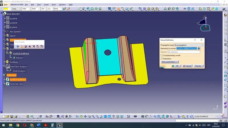
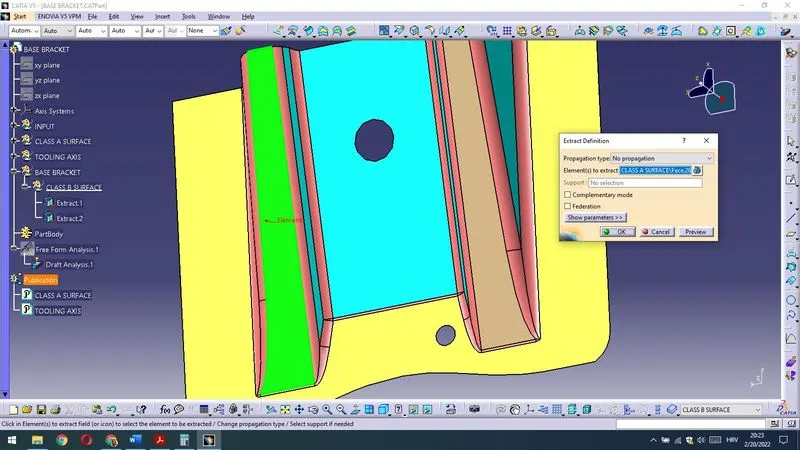
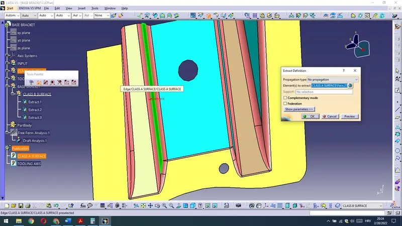
Then I have untrimed those extracted surfaces.
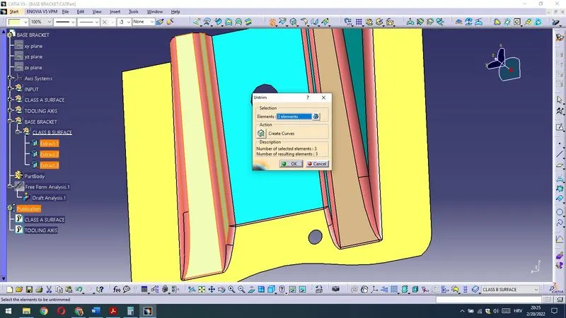
After that I have extrapolated it as it is shown on image bellow.
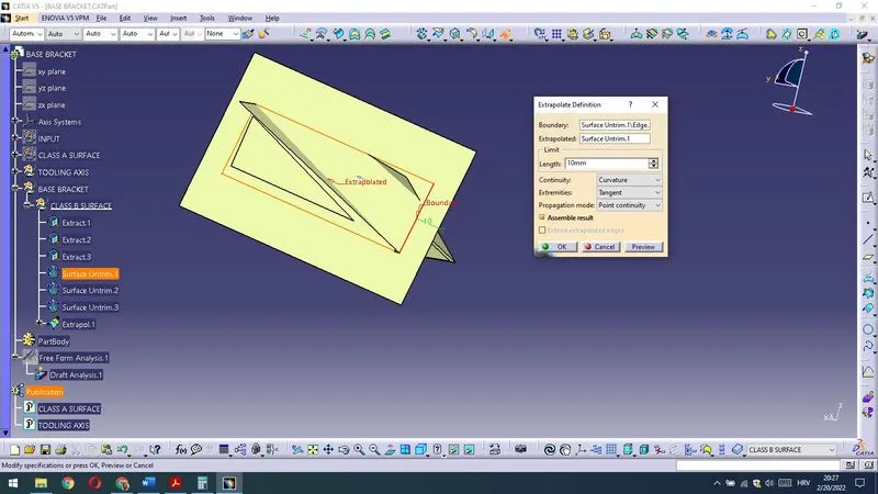
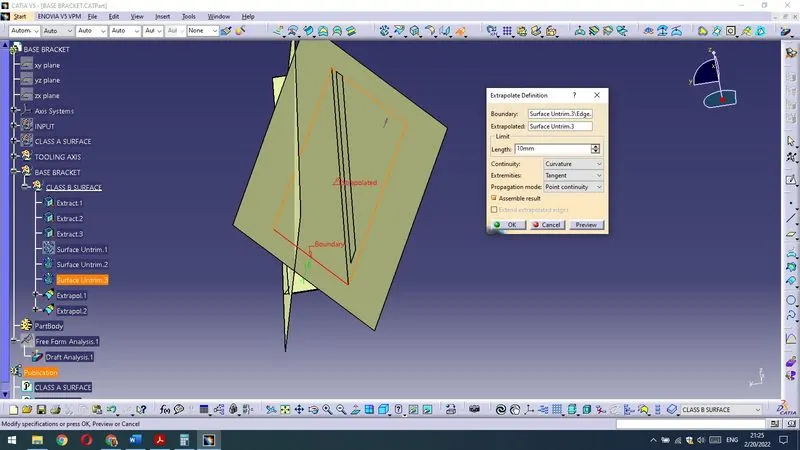
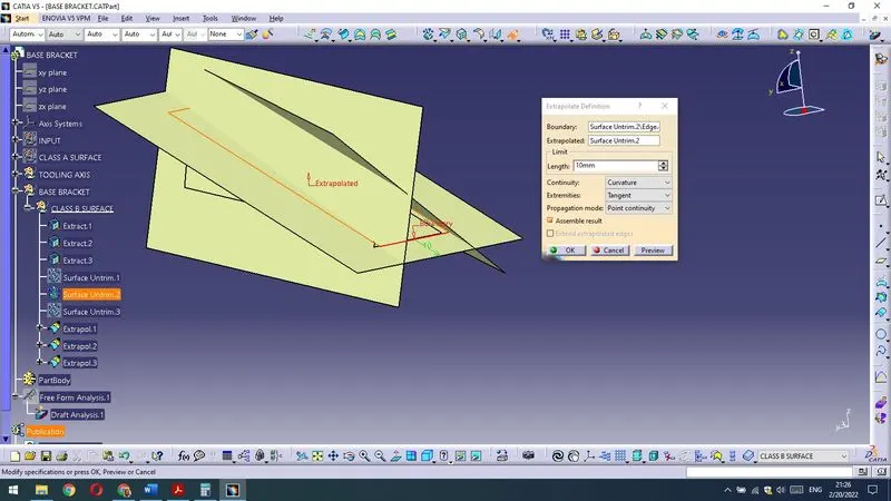
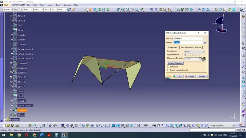
Then I have offseted for a 2,5mm inside those extrapolated surfaces and trimmed.
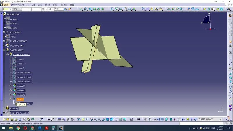
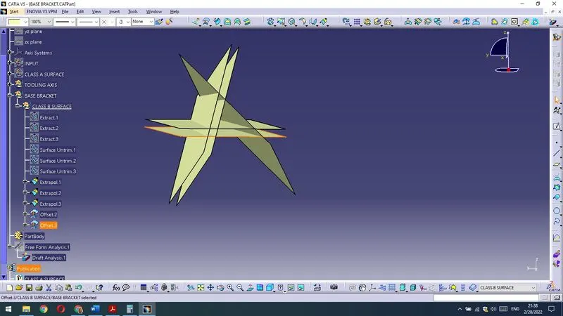
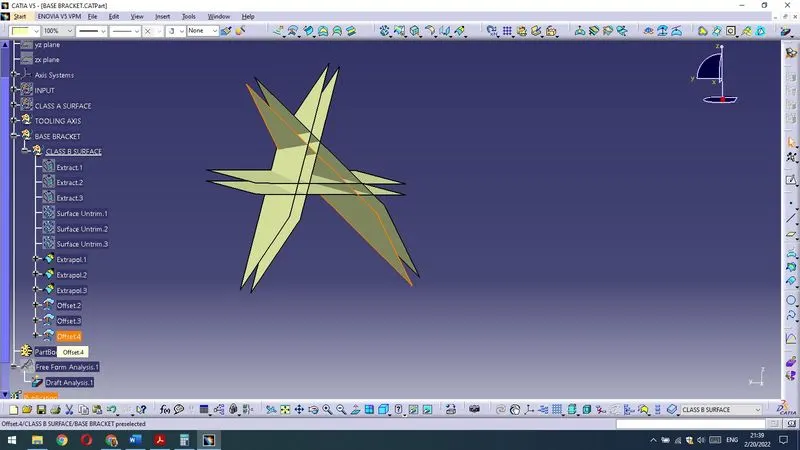
Then I have trimmed offseted surfaces.
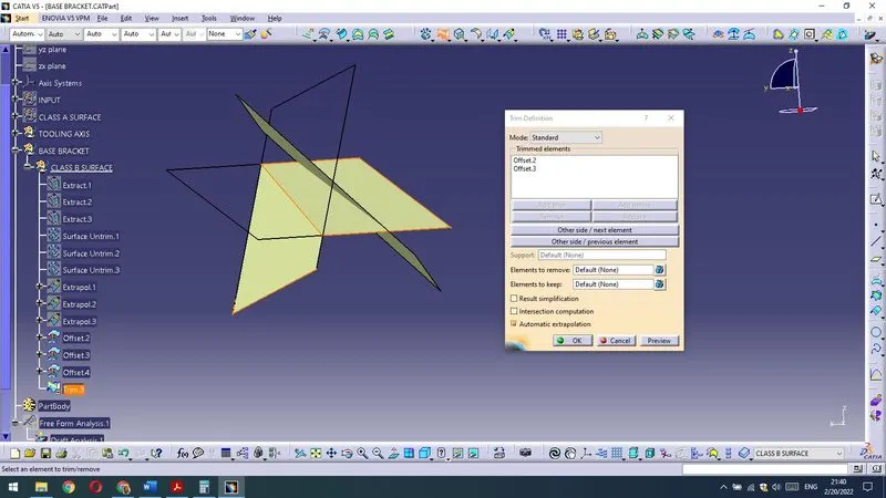
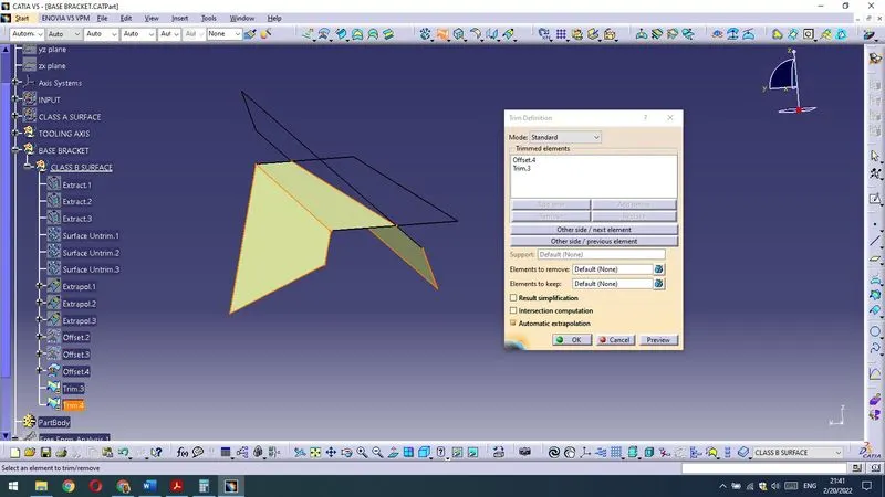
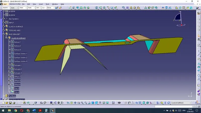
The same procedure is for the drafted surfaces on the other side.
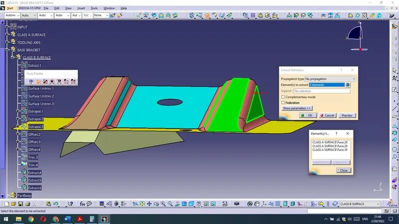
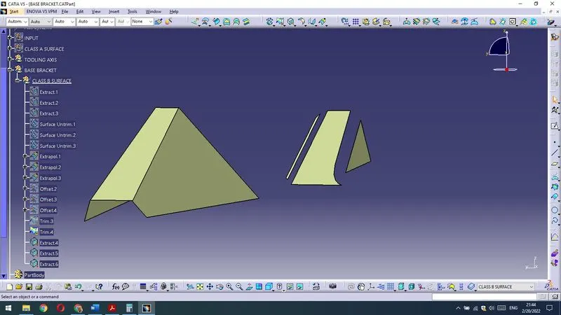
Then extracted then untrimmed and extrapolate surfaces as before.
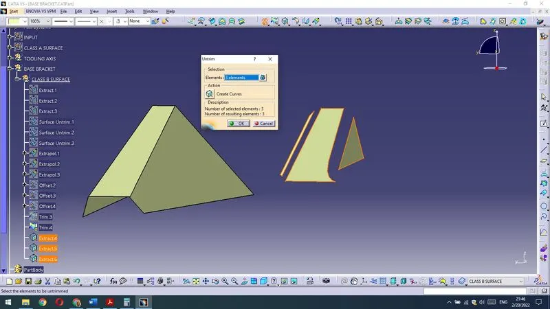
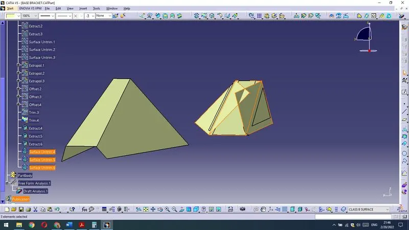
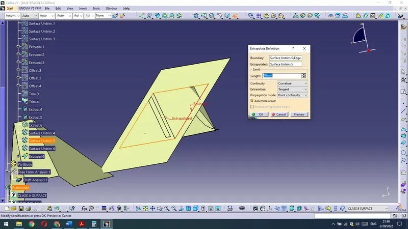
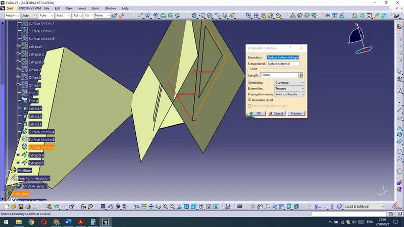
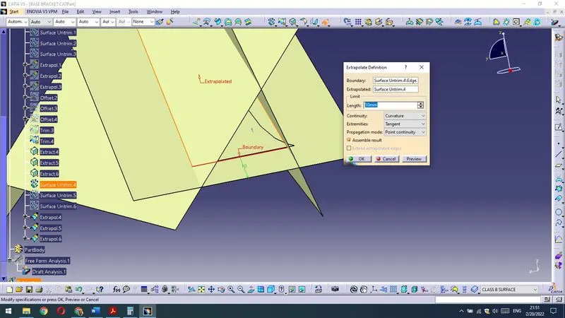
Then I have offseted it for a 2,5mm inside.
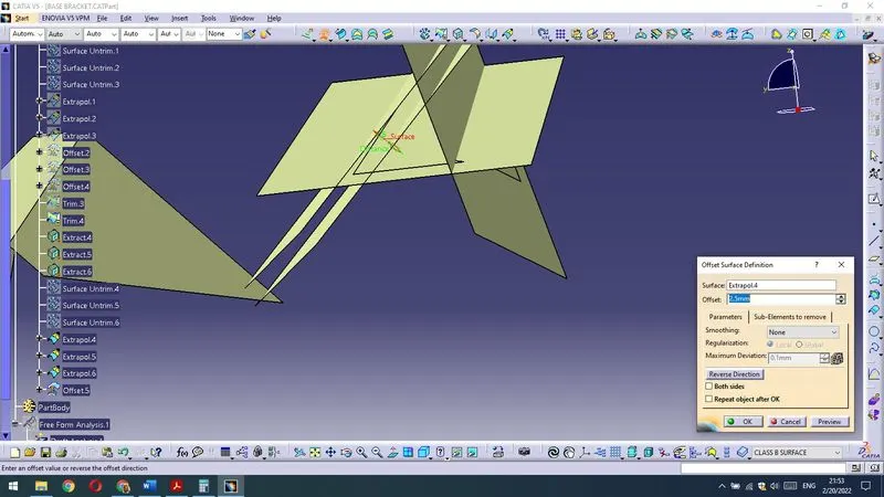
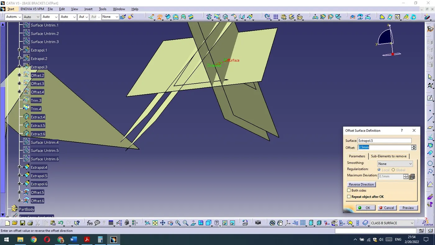
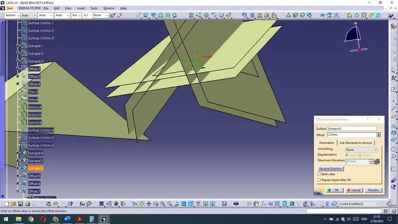
Then I have trimmed it.
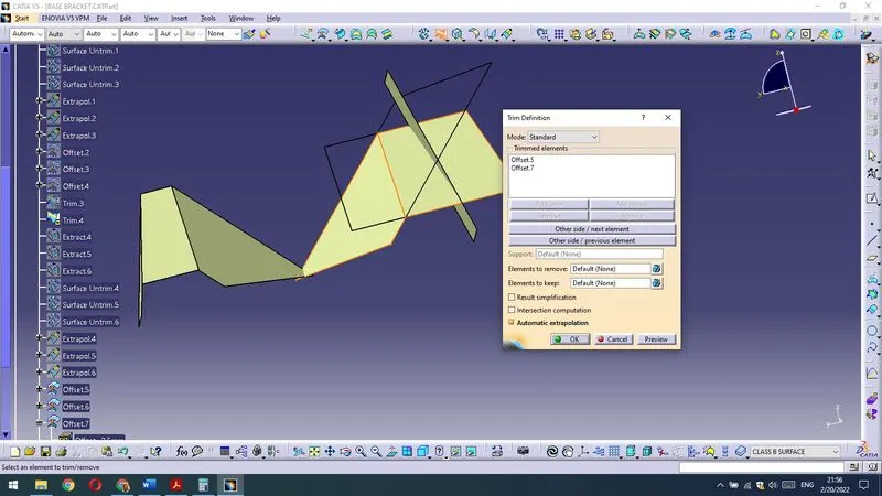
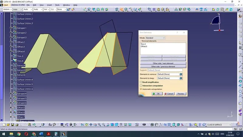
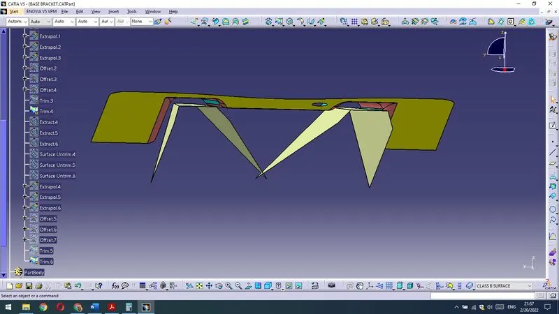
Then,the big surface with a circle has left.I have also done the same procedure for it.
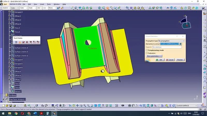
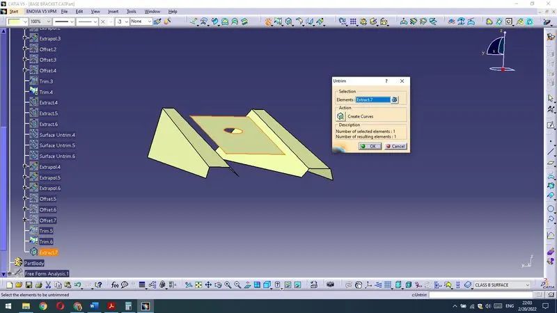
Then extrapolate and 2,5mm offset.
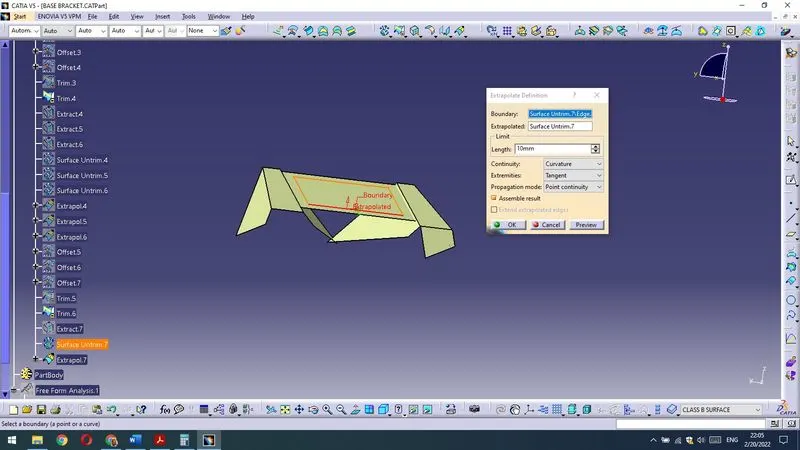
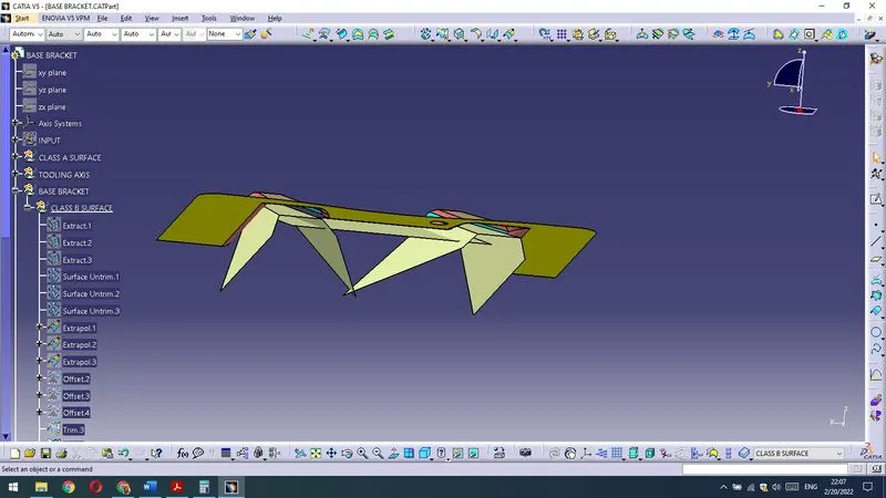
Then trimmed it.
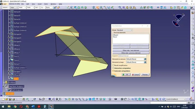
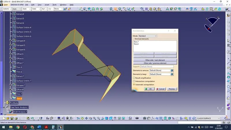
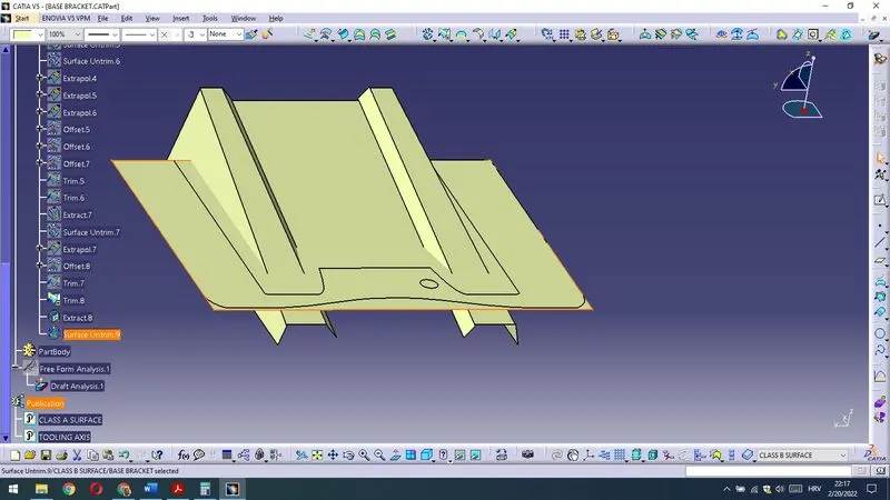
It is only big yellow surface left – then I will deal with it also on the same way – extract – untrimm – offset – trimm.
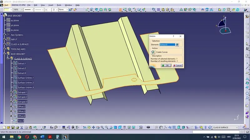
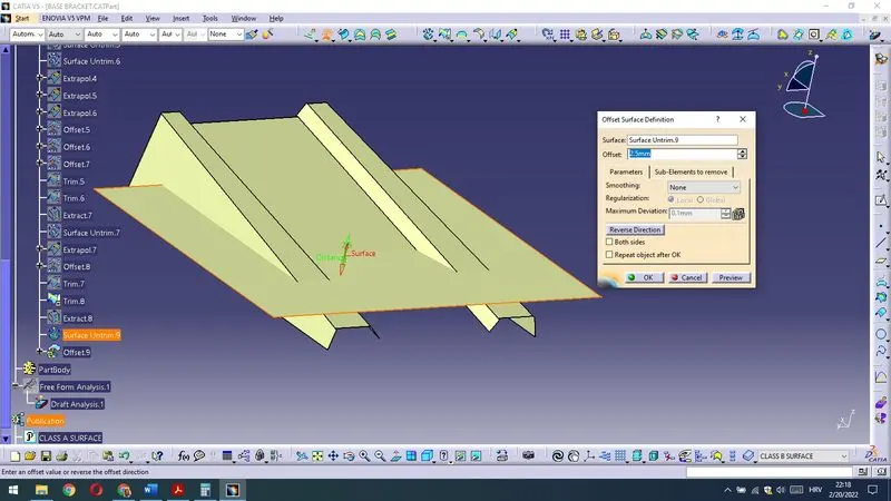
Then inside offset 2.5mm.
Then I have trimmed it.
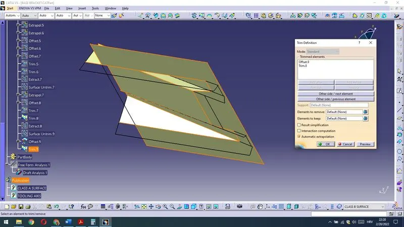
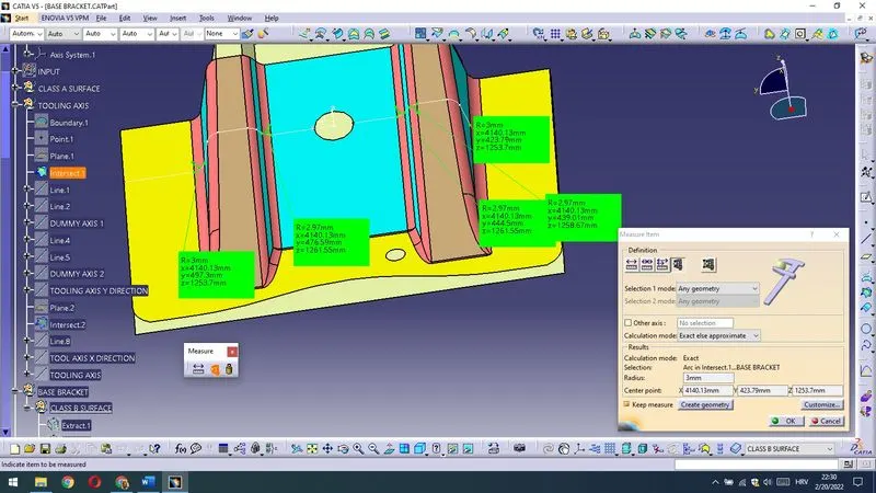
Now I have to define and draw fillets.For that purpose it is the best to measure the intersection with a perpendicular plane in Y direction (there are surfaces under angle also) – as a result we see that Class A Surface has a fillet of 3mm and we should increase it for a Part thickness (2,5mm) and we are getting 5,5mm fillet as a result on the one side and on the other 3mm decreased for a 2,5mm I am getting 0,5mm.
The fillets are then drawn as it is bellow shown.
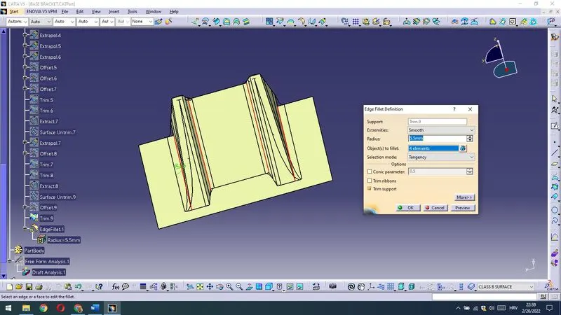
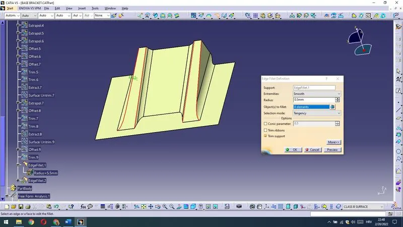
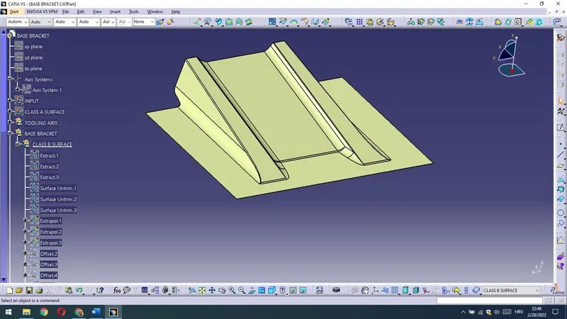
CLASS B SURFACE is constructed (renamed and changed properties) and it is ready for Publishing.
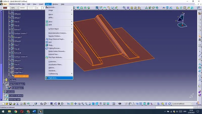
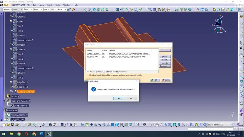
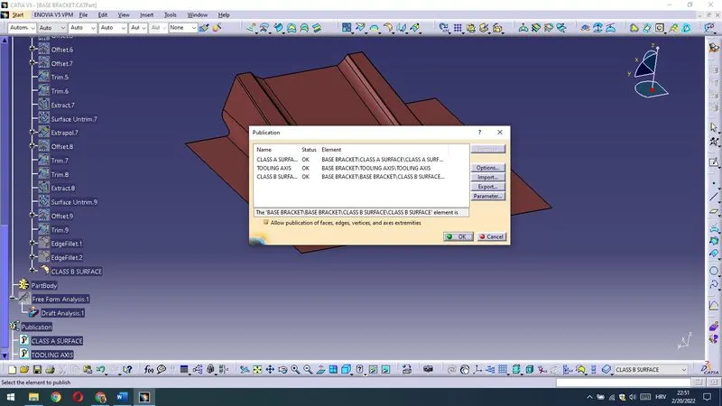
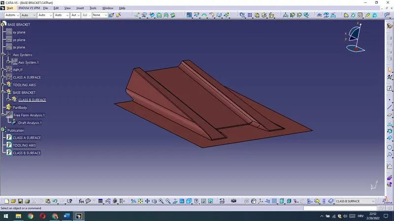
I have moved CLASS A SURFACE under BASE BRACKET and reorder it.
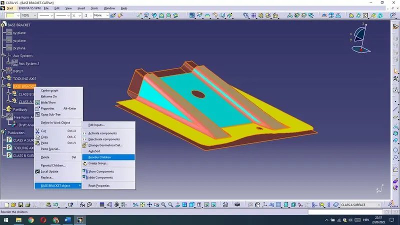
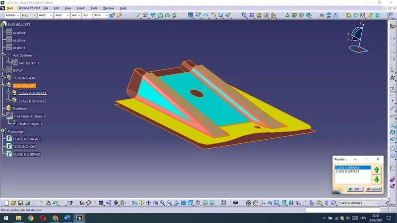
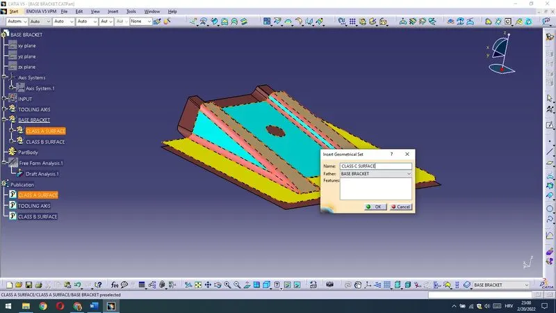
Now it is time to construct CLASS C SURFACE.I am first Inserted CLASS C SURFACE Geometrical Set under BASE BRACKET.
Then I have extracted boundaries of the CLASS A SURFACE and have shown TOOLING AXIS and a circle boundary.(I have also done extrapolation on CLASS B SURFACE). Then with sweep I will be constructed surface on the boundaries as shown bellow.
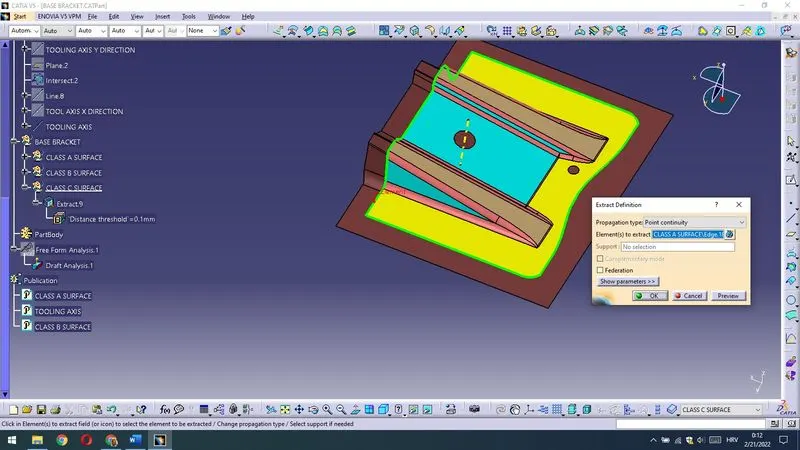
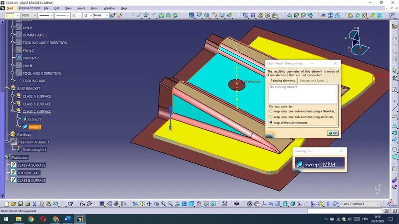
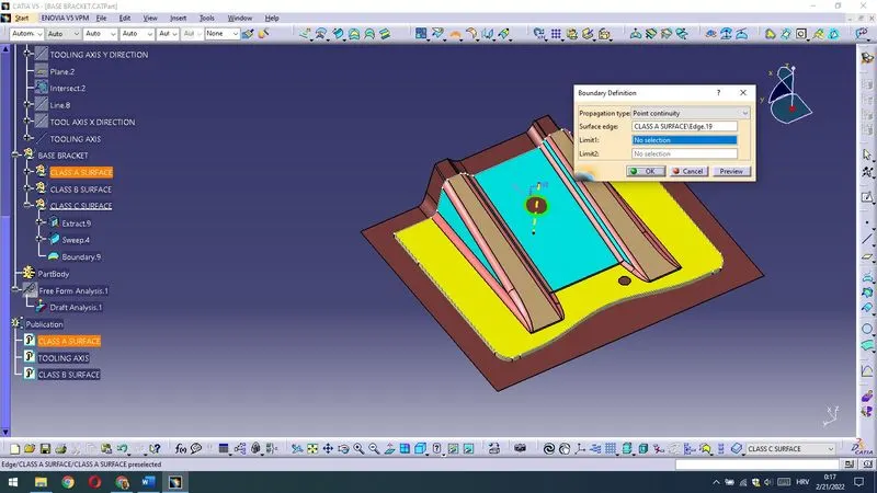
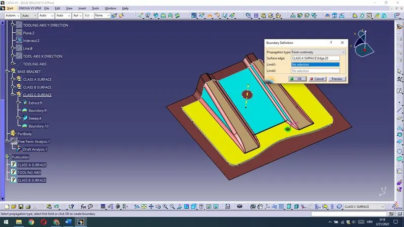
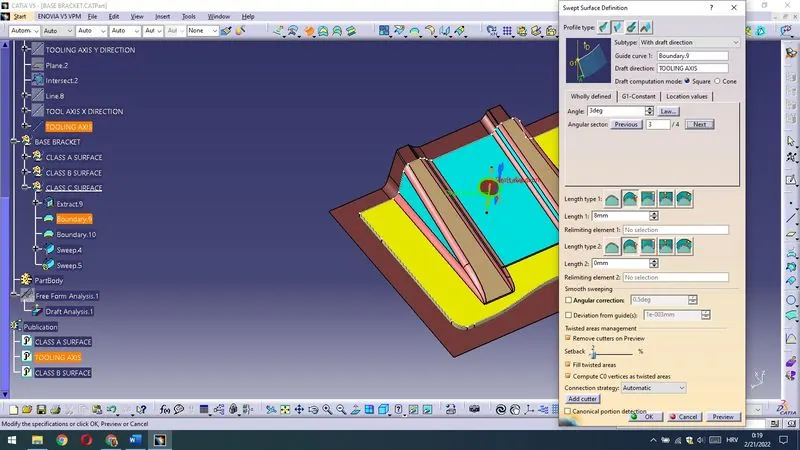
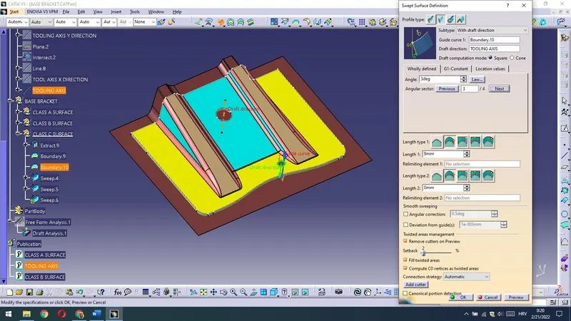
After sweep I have seen these very small irregularities,I have removed it with extract – trimmed it and mada a surface smooth.
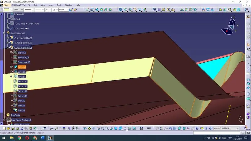
On the end I have get smooth edges .
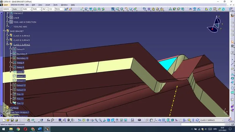
Then I have renamed and Published constructed CLASS C SURFACE.
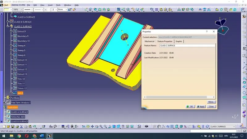
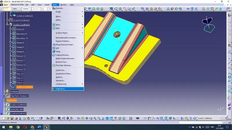
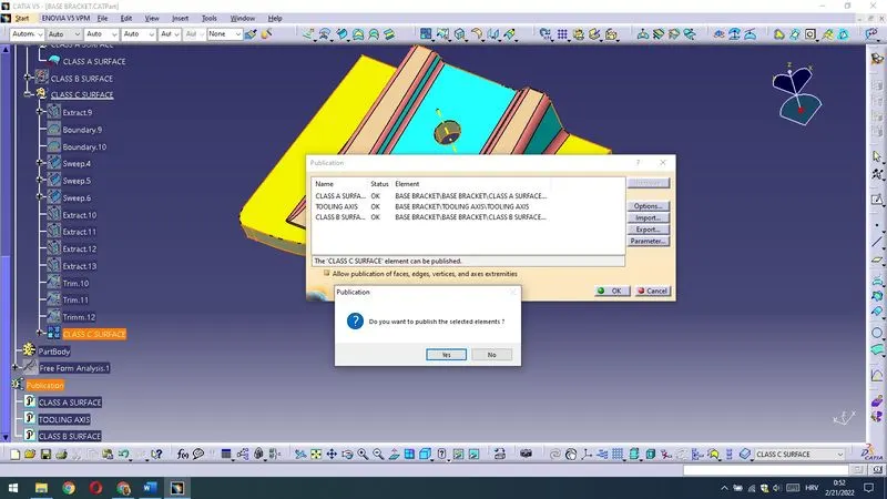
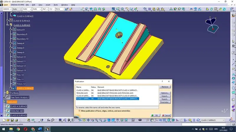
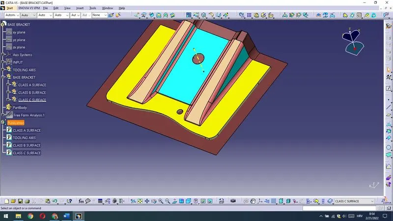
Now I will Join CLASS SURFACE A and CLASS SURFACE C and trimm it with CLASS SURFACE B.
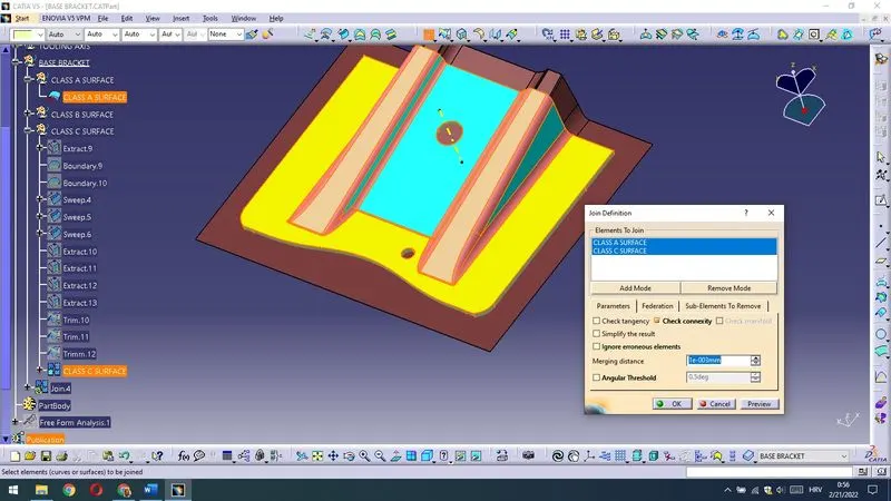
And then I have trimmed it with CLASS B SURFACE to get closed contour.
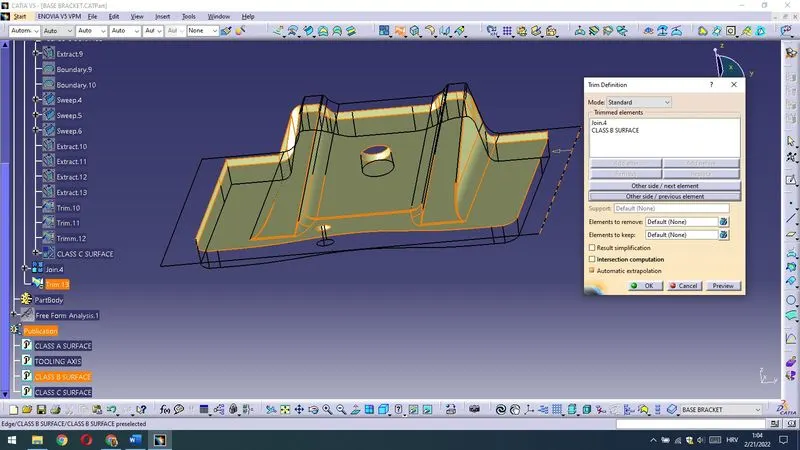
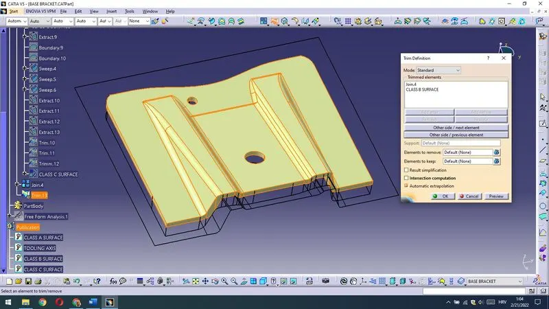
Constructed model will be given BASE BRACKET name.
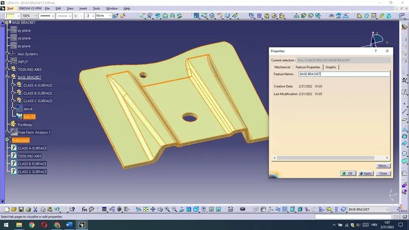
Then I will make it as a Solid part with a Close Surface option under Part Design.
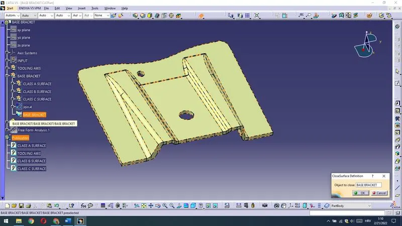
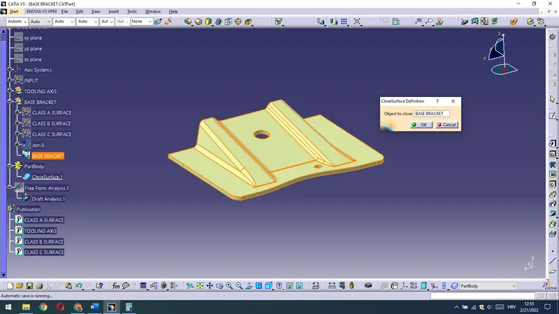
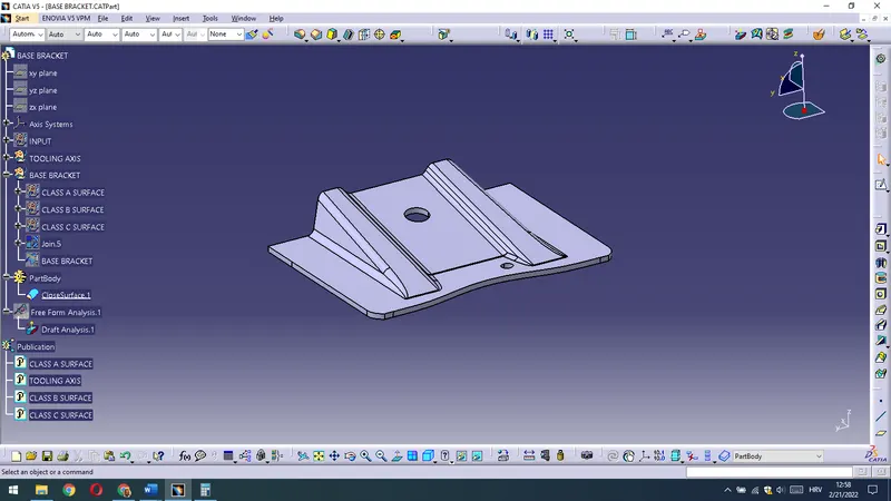
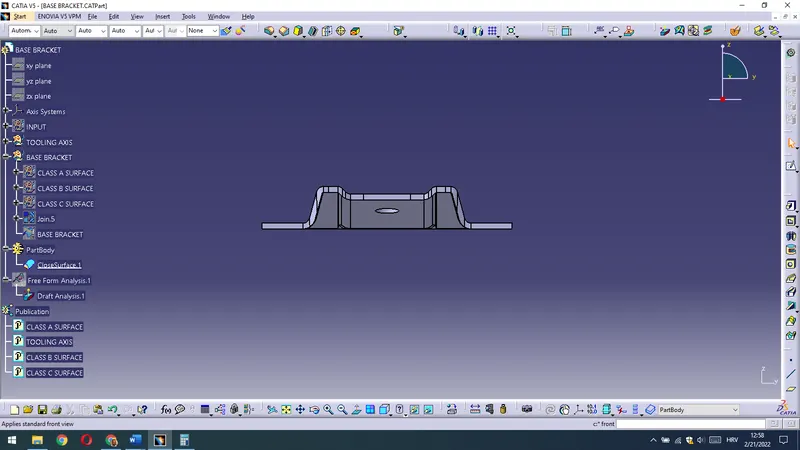
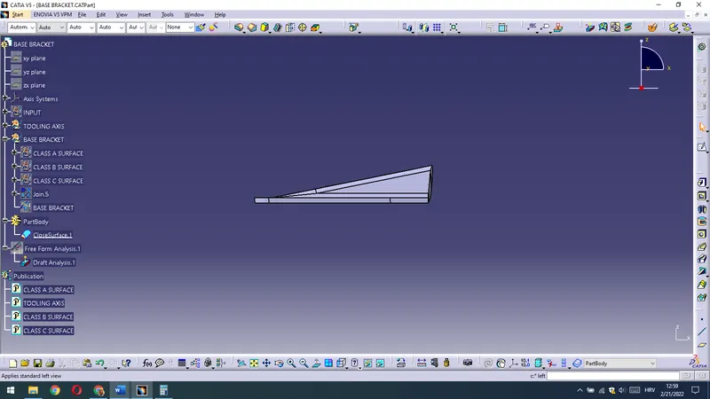
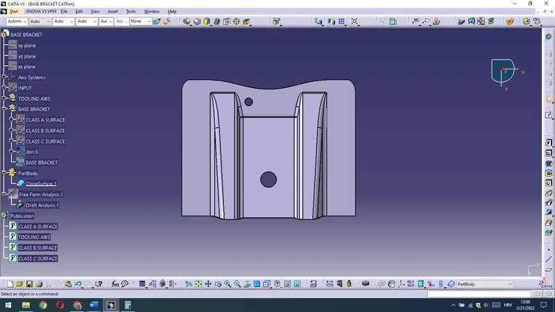
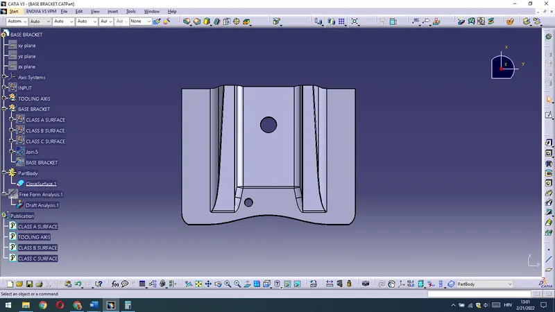
So we have constructed Part with TOOLING AXIS and CLASS A SURFACE,CLASS B SURFACE,CLASS C SURFACE.
Best regards,
Ivan Tole