Week 8 - Challenge 3 - Switch Bezel Design
Hi fellows,
SWITCH BEZEL
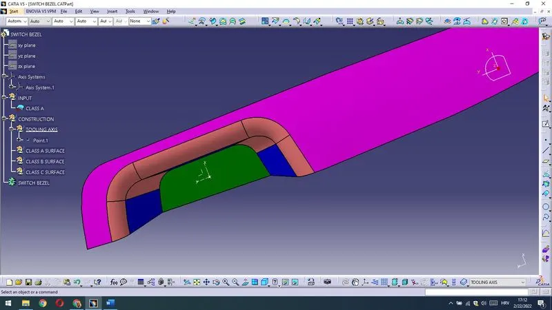
After I have opened a file I have taken a look on the Part .I have taken in consideration surfaces,drafts and possible movement out of core/cavity of the mold.
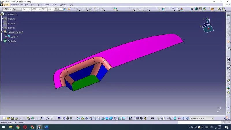
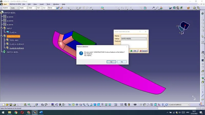
I have also renamed PartBody as a SWITCH BEZEL and inserted new Geometrical Sets and renamed it as a CONSTRUCTION.
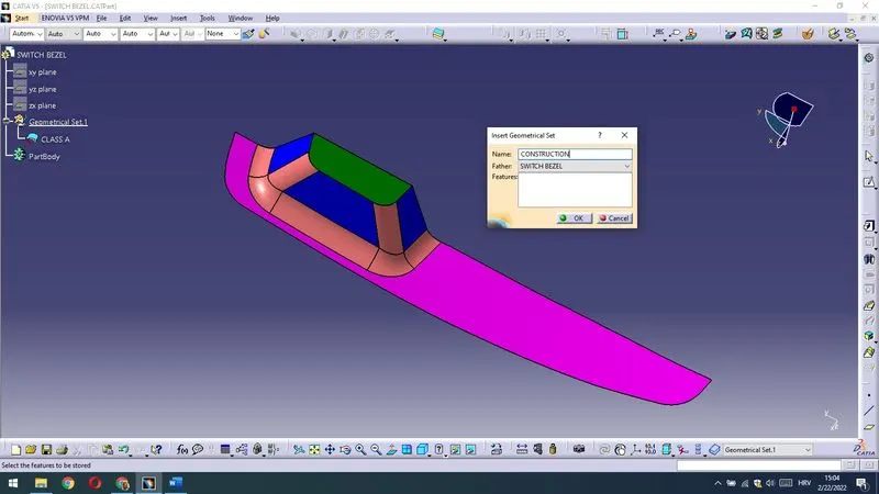
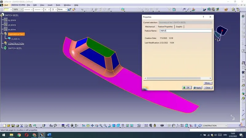
Geometrical Set with CLASS A I have also renamed as a INPUT.
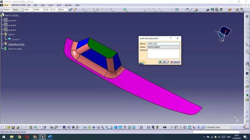
Under CONSTRUCTION Geometrical Set I have inserted TOOL AXIS,CLASS A SURFACE (there I have copied CLASS A Surface from Input),CLASS B SURFACE and CLASS C SURFACE.
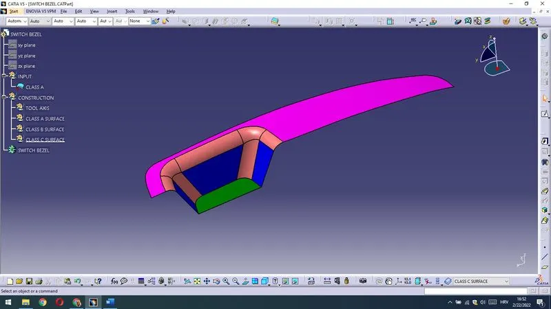
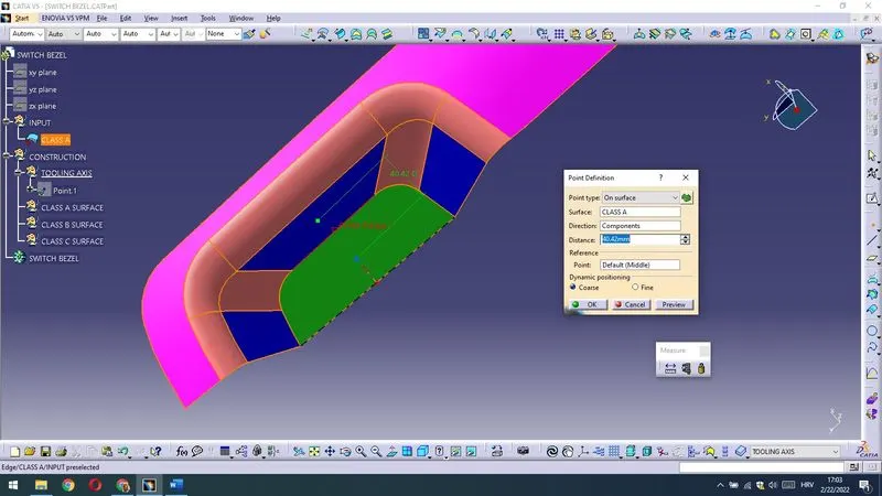
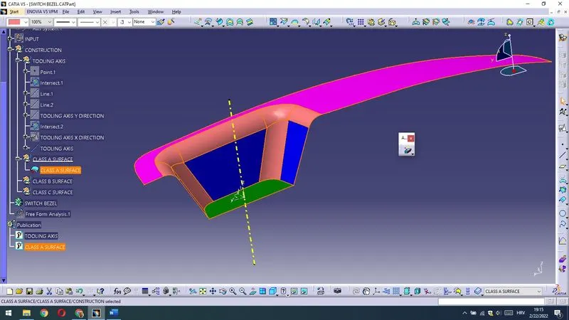
Then I have taken a green flat surface for a best possible solution to put a tooling axis on – I had to draw a piont on it where I could insert axis system to make intersections.I have taken a point aproximately in the middle of the surface.
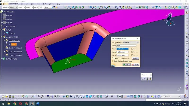
I had unchecked Current in the Axis System Definition dialog box.
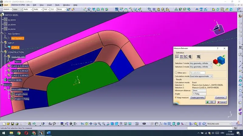
The Angle between YZ plane and a blue surface is 1,75deg – that means it should be taken in consideration.The blue surface in front of the YZ plane seems problematic – draft is too small,had to deal with it.
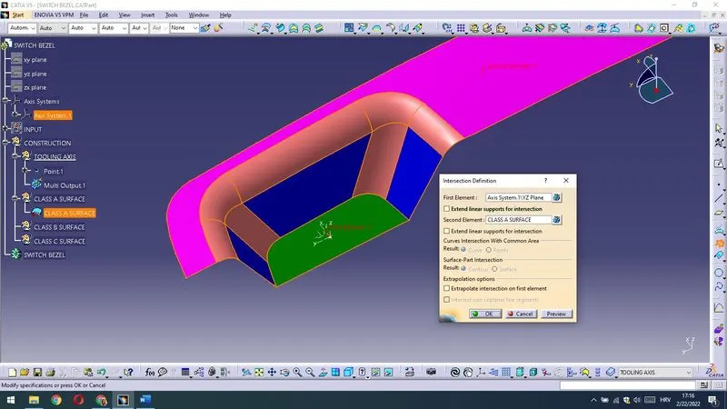
Now,I should construct TOOLING AXIS for a given part.So,at first I have done intersection YZ plane with a CLASS A SURFACE (copied from the INPUT).
There I have made a lines to get a bisecting line of it in the given point.
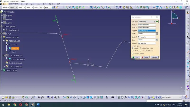
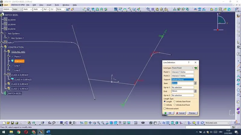
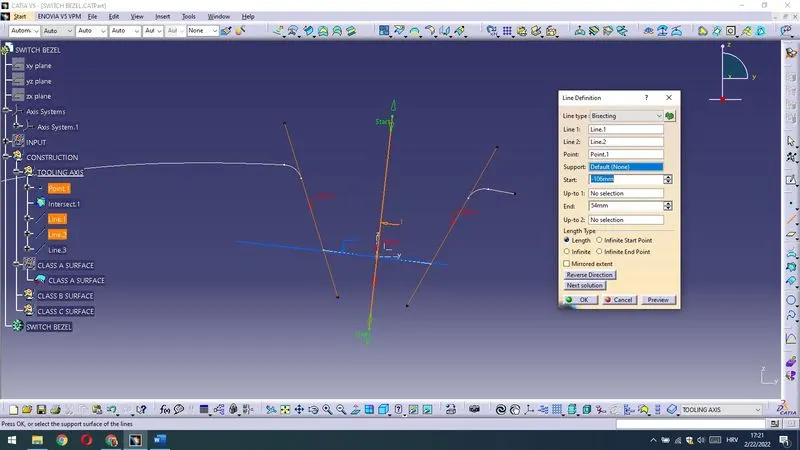
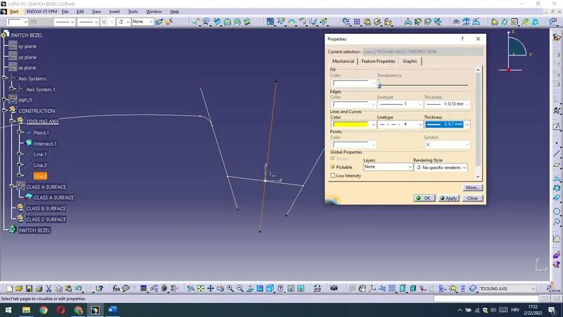
That will be TOOLING AXIS Y DIRECTION (I have renamed it and change properties).
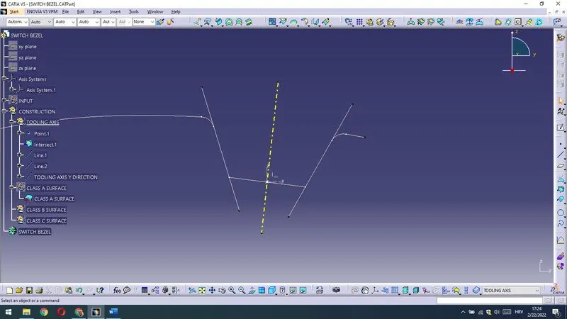
Now I am going to construct tooling axis in X direction.First I have made a intersection of plane XZ and a CLASS A SURFACE.
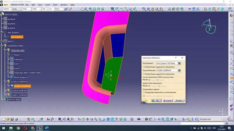
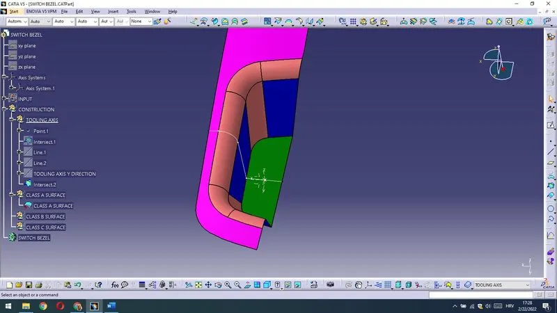
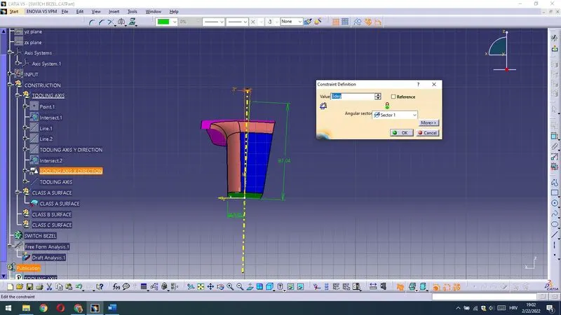
I do not have a two lines to lie my construction lines on,but I could draw a line under the angle with Z axis to have a satisfactory inclinations regarding draft angle.
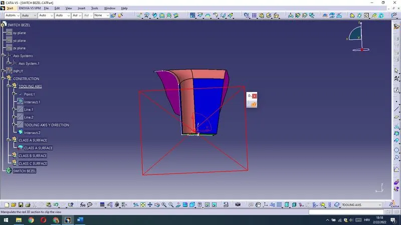
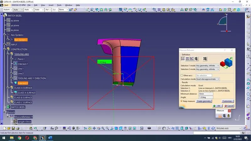
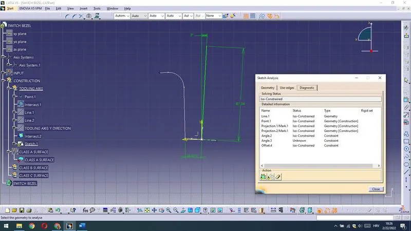
Now I will rename the axis as a TOOLING AXIS X DIRECTION and change a properties.

Then I have constructed TOOLING AXIS as a bisected line of the TOOLING AXIS X DIRECTION and TOOLING AXIS Y DIRECTION.
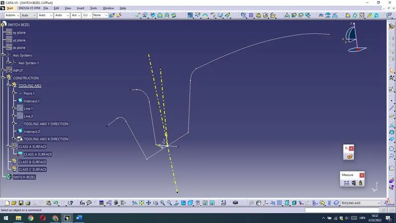
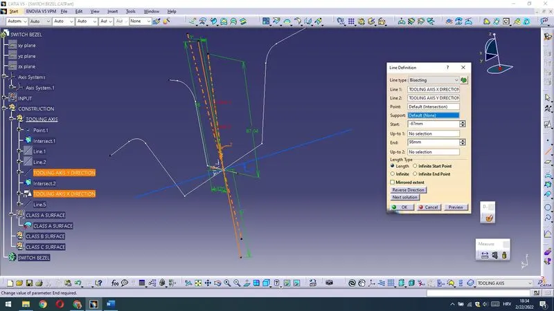
Then I have renamed a line as a TOOLING AXIS and changed a properties of the line.
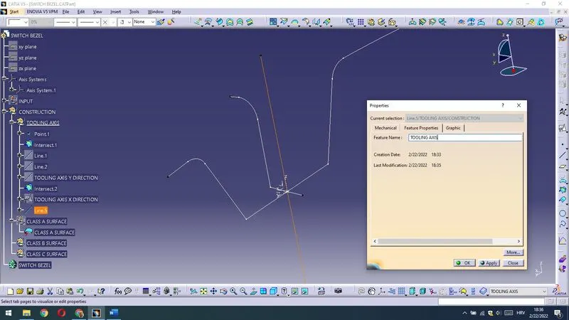
I have published TOOLING AXIS and a CLASS A SURFACE.
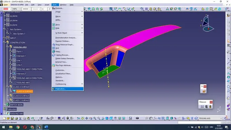
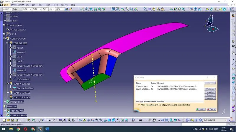
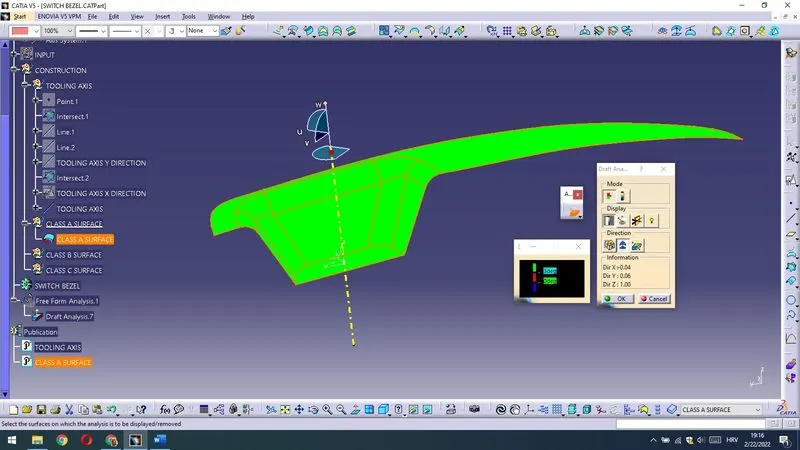
Now I will investigate TOOLING AXIS if I get a satisfactory solution for Draft Analysis.First Customize View Parameters to see if Material is applied.
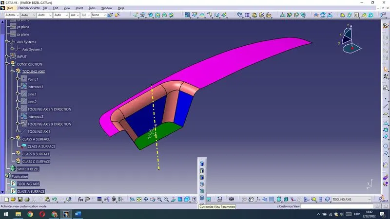
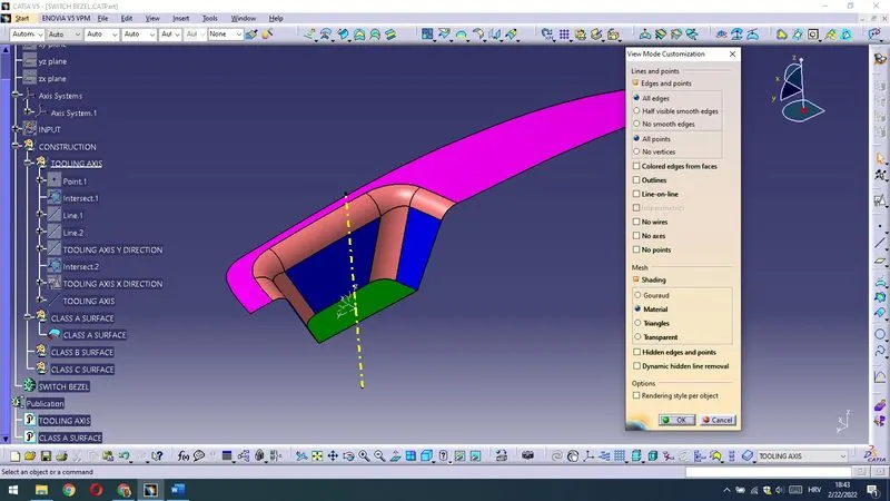
It is applied - I can move further.With the option Feature Draft Analysis I get dialog options as bellow.
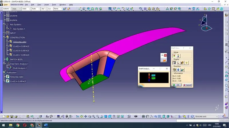
Then I had Uses the compas,click on the field in dialog box with compas and dragg the compass on the TOOLING AXIS as shown on images.
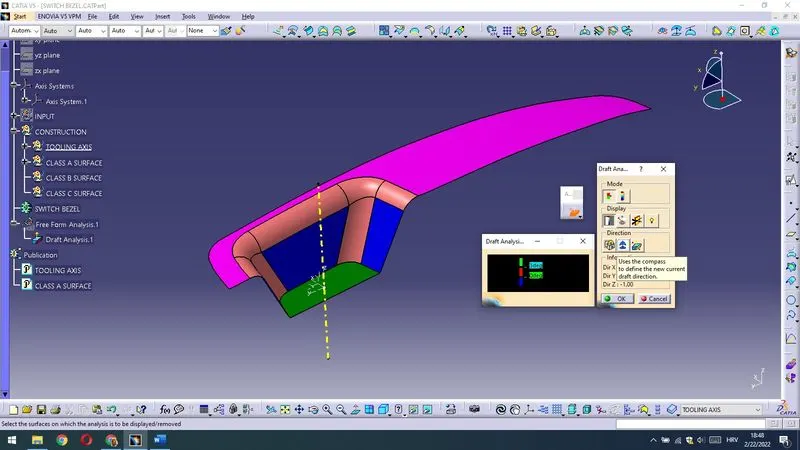
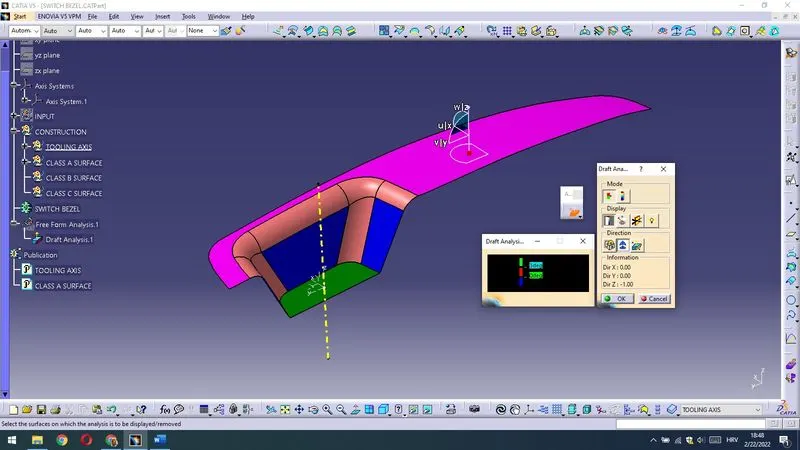
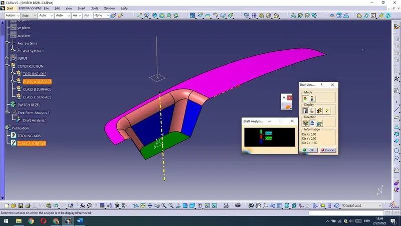
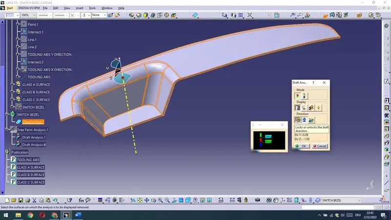
Then I have locked the compas.
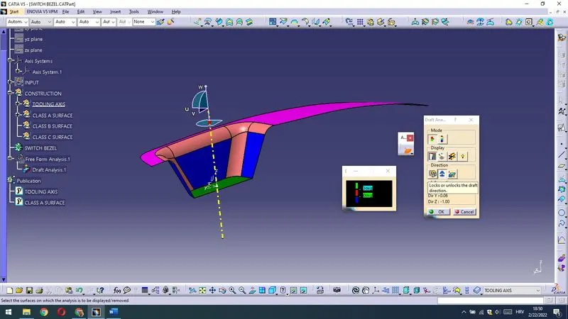
I had a unsatisfactory solution – that means I should increase angle of the TOOLING AXIS X DIRECTION.
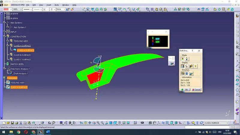
I have increased angle from 3deg to 5deg.
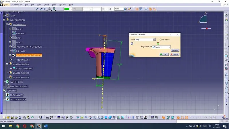
Now I will see the result of the new draft analysis.
Now is all good as shown bellow.
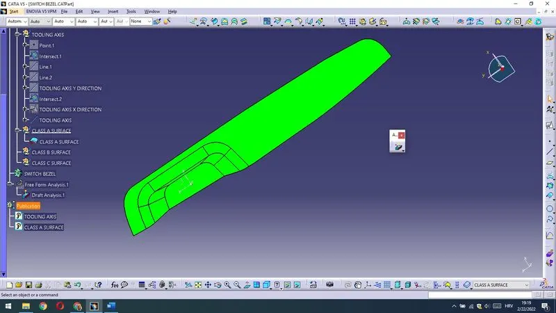
So,now I am going to construct CLASS B SURFACE.
As I will for B surface use walls,bottom and top surface I will insert those Geometrical Sets in CLASS B SURFACE Geometrical Set.Fillets I will not at first take in consideration and extract because these features are problematic with offsetting.
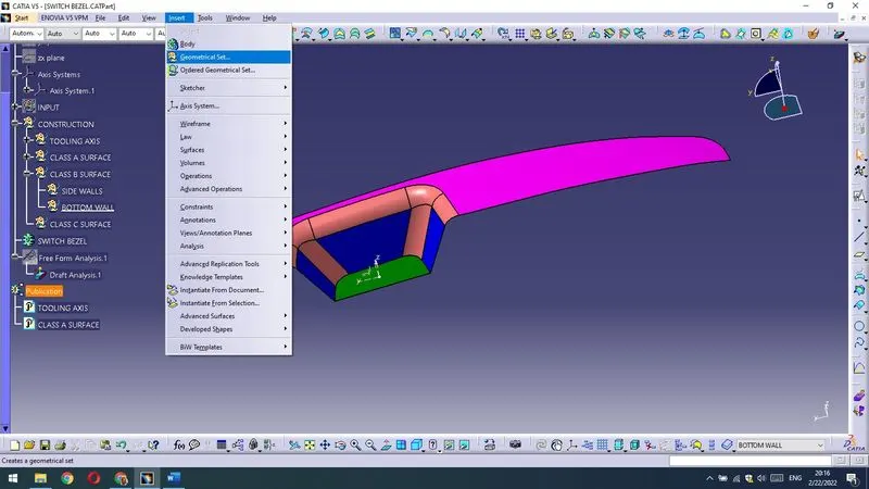
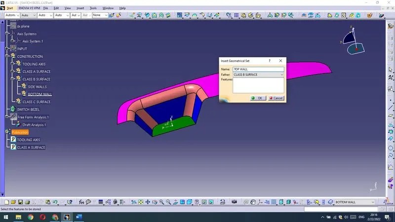
I will extract and offset walls for a thickness value (2,5mm) and trim them.
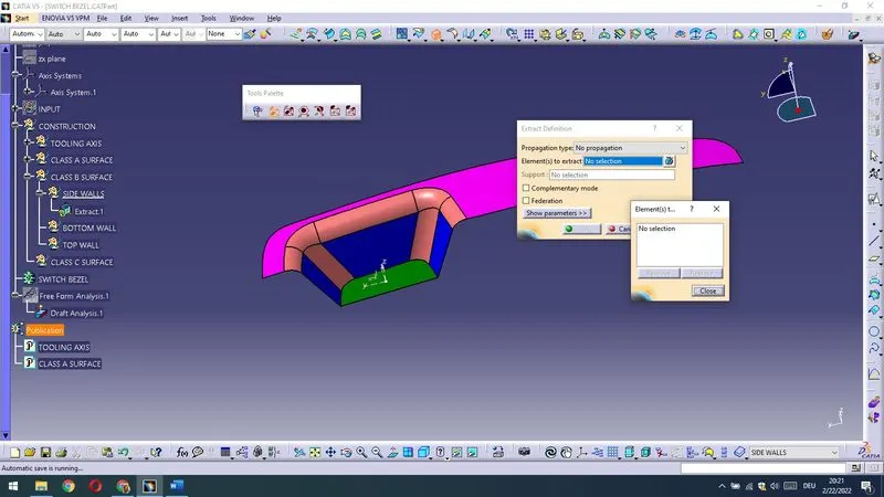
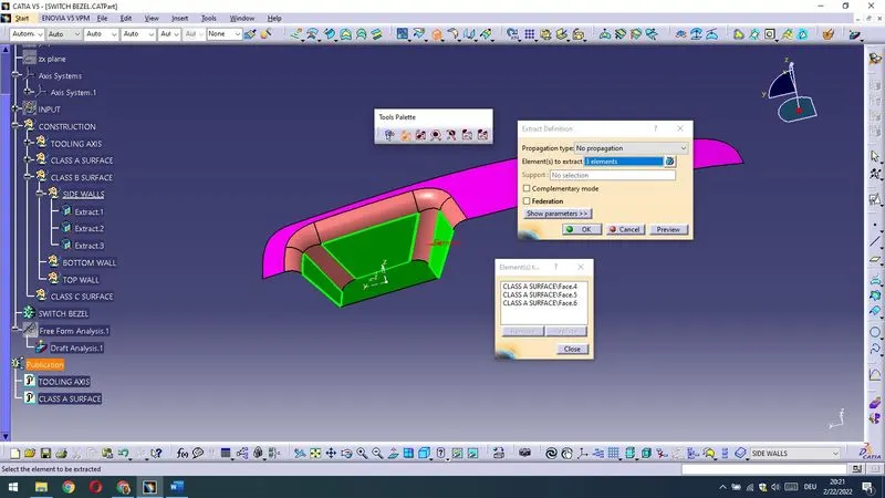
After extract follows untrim.
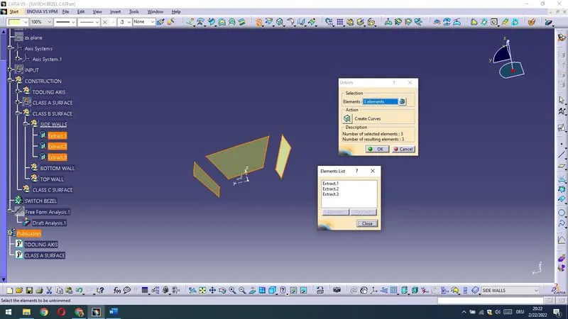
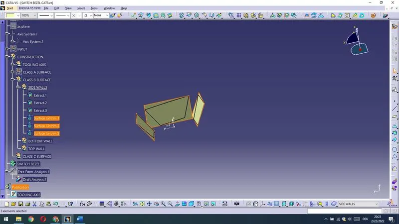
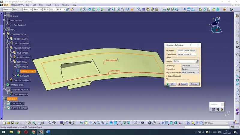
Then I have extrapolated untrimed surfaces.
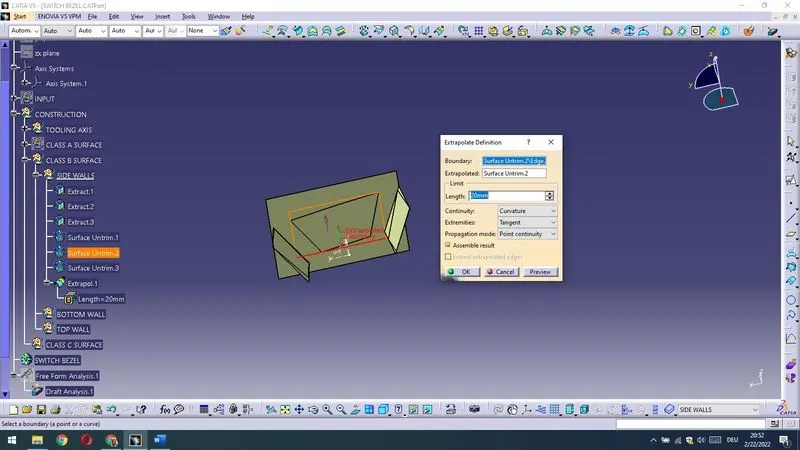
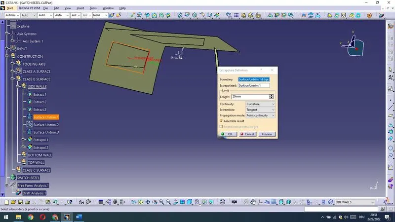
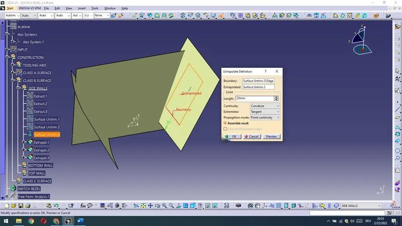
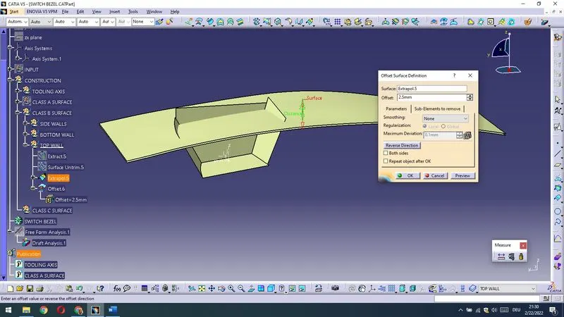
Now comes 2.5mm offset.
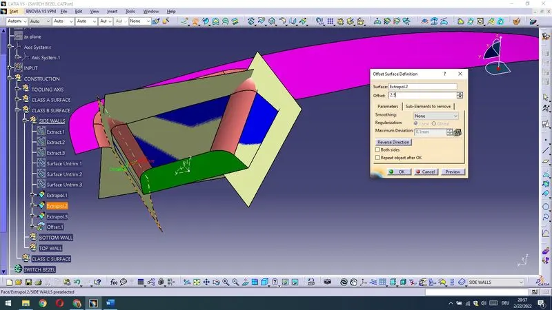
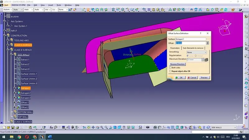
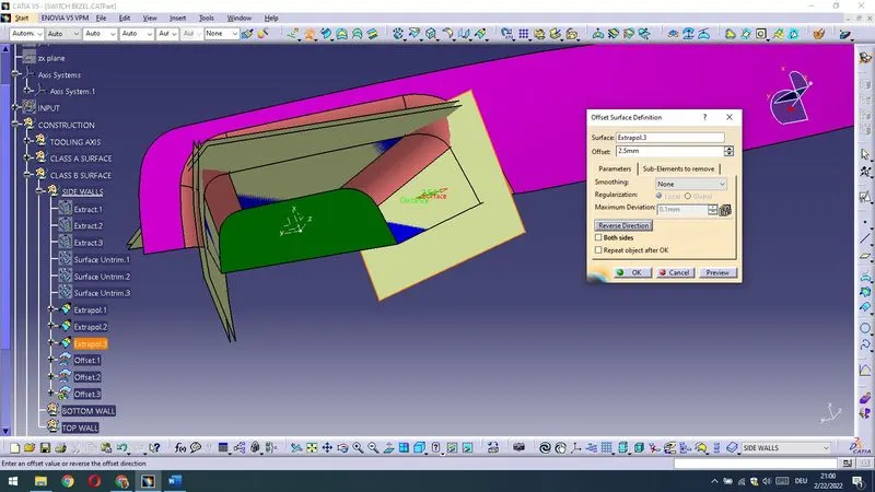
Now I have trimed it.
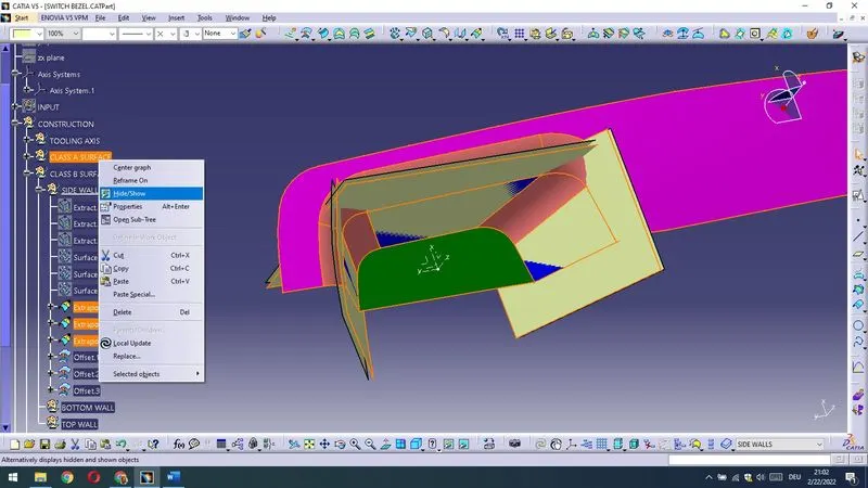
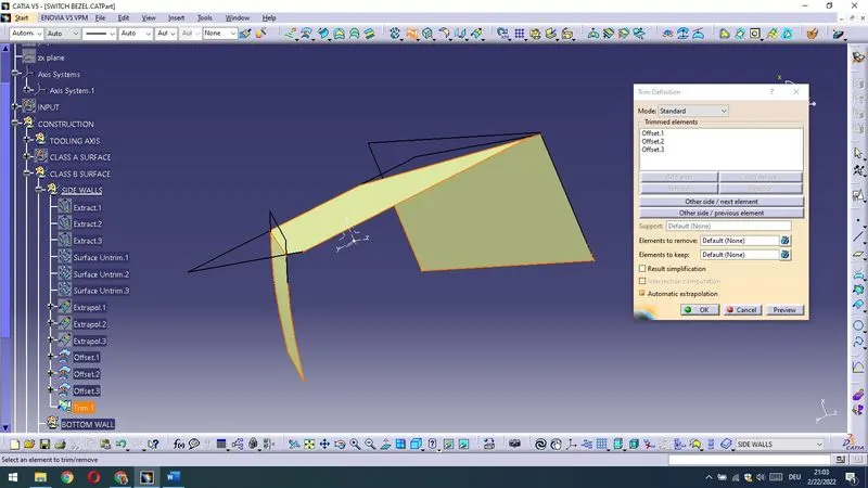
The same procedure is for bottom: extract – untrim – offset – extrapolate and trim.
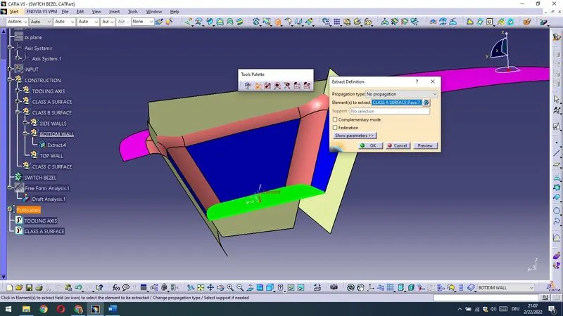
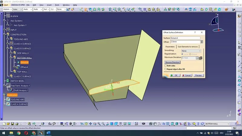
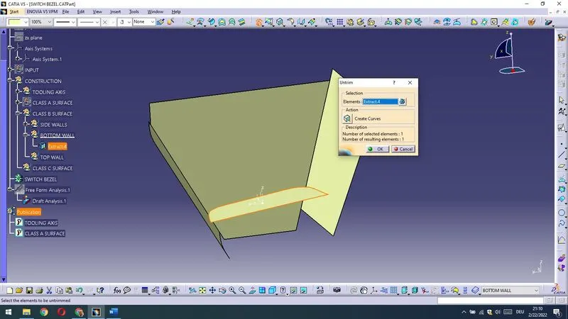
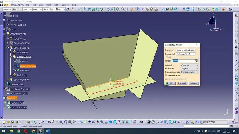
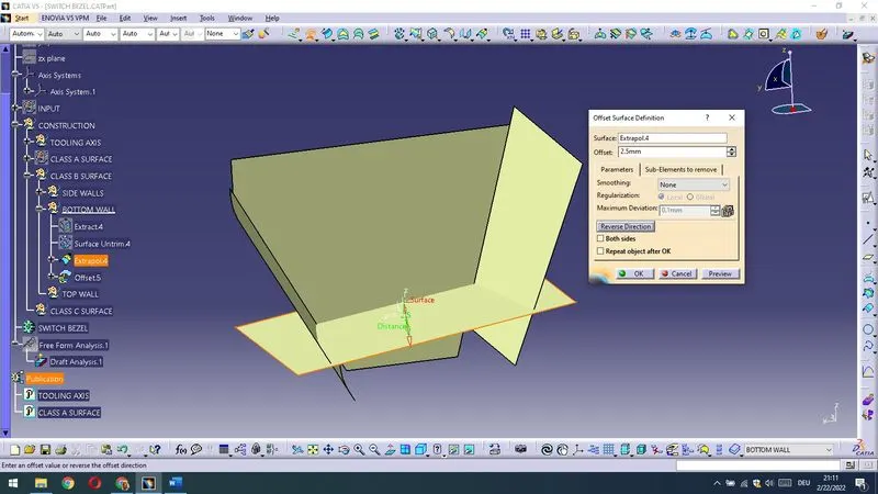
Now comes trim with SIDE WALLS Surface.
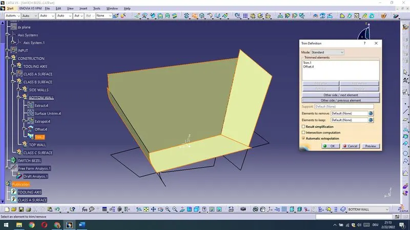
So,as can be seen till now is all done well.
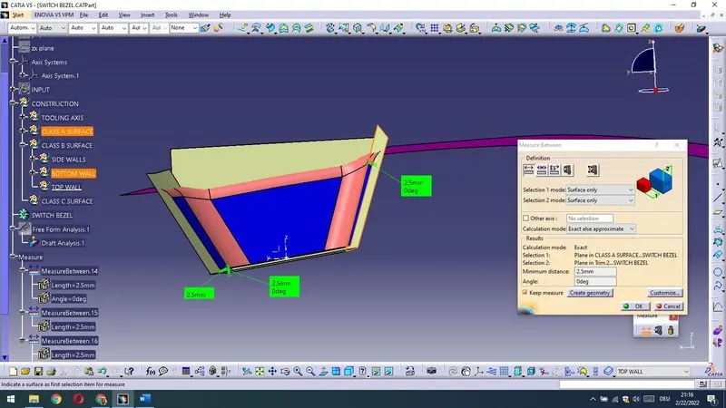
Now I have done the same for Top surface -in the Geometrical Set TOP WALL .
Extract first.
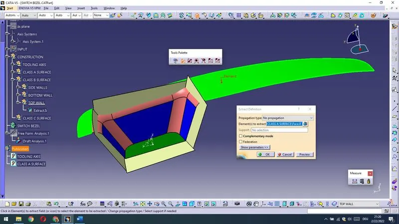
Follows untrim
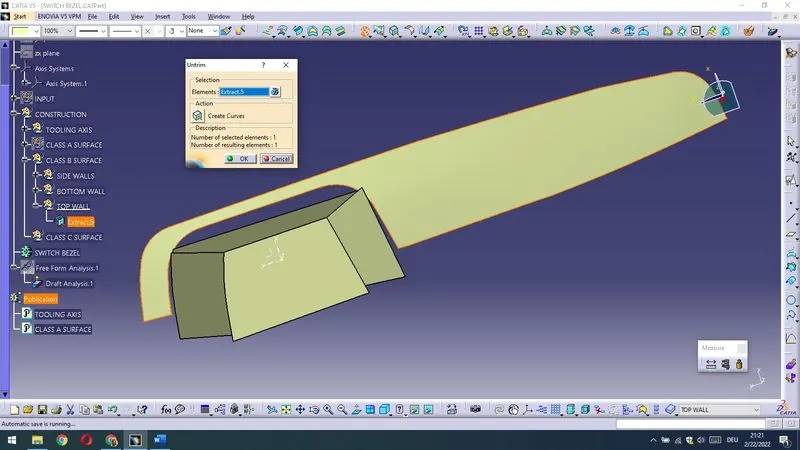
Then extrapolate
Then offset
And finally trim.
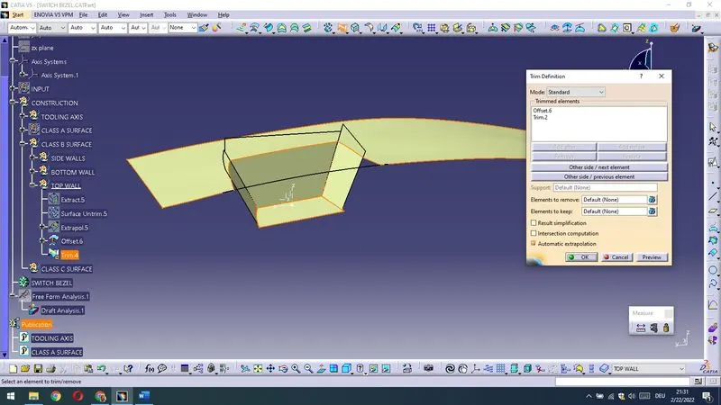
Now I should deal with fillets.For the fillet on top wall it is clear that is 14mm and for the fillets on side walls it is unknown because fillets are under the angle at the connection – that means I should investigate the fillets.
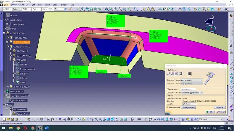
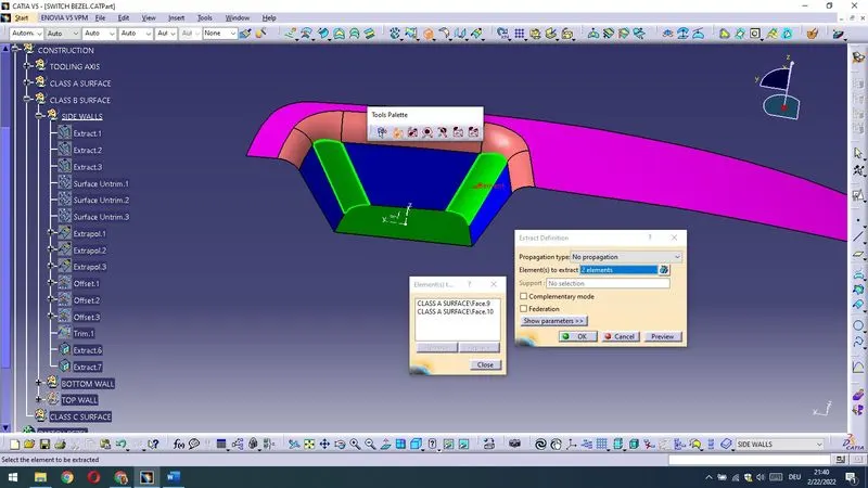
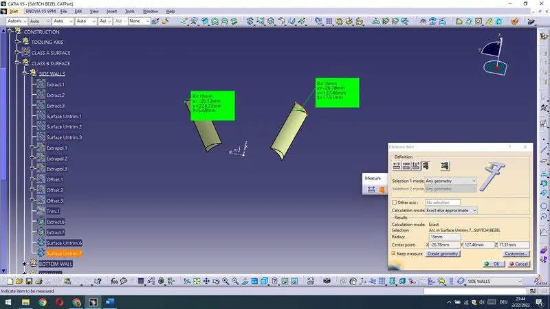
It is done (determining the unknown fillets value) following procedure shown down.At first I have extracted those fillets under angle.
Then I have untrimed it and measured the given values.
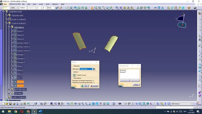
As we can see the fillets have 15mm value.
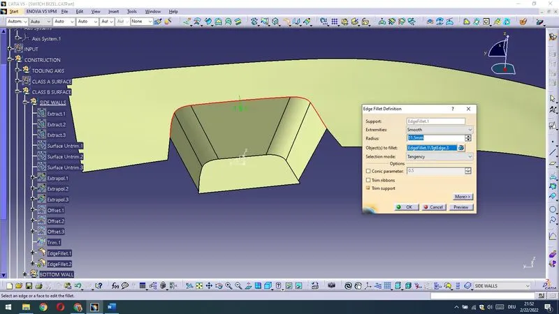
Now I have applied those established fillets – 14mm on top and 15mm on side walls taking in consideration thickness value of the Part (2.5mm).
In the case here the fillet value 15mm should be increased for 2.5mm and fillet 14mm should be decreased for that value.

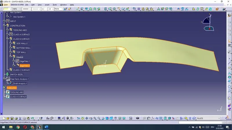
I have inserted new Geometrical Set called Fillets under CLASS B SURFACE and moved the fillets in that Set.
CLASS B SURFACE I have published.
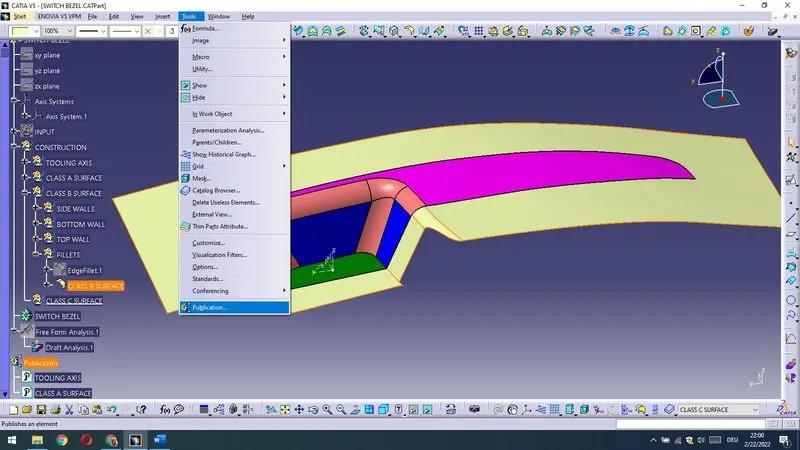
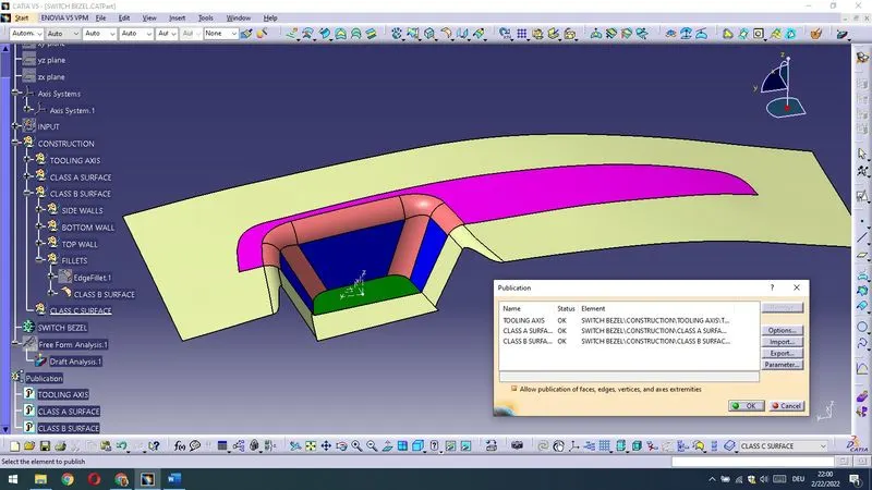
Now is time to deal with CLASS C SURFACE.
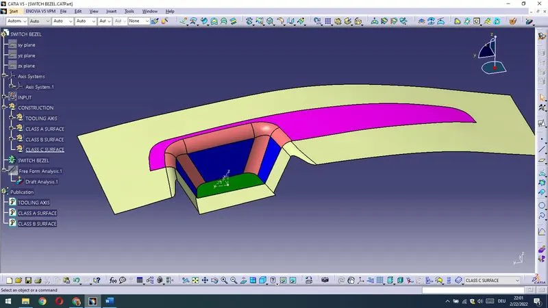
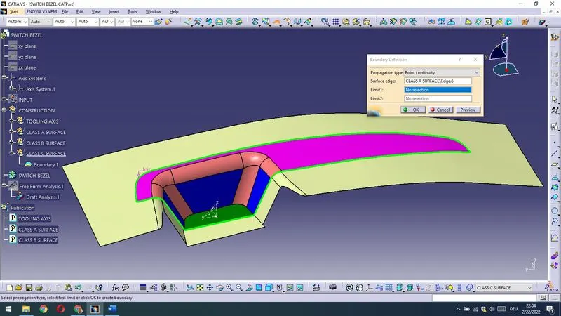
At first I have made boundaries of the CLASS A SURFACE.
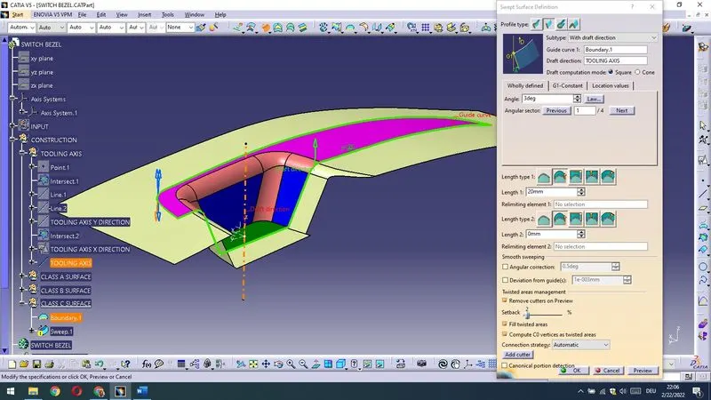
Then I made Surface with Sweep command on the basis of that boundary and TOOLING AXIS.
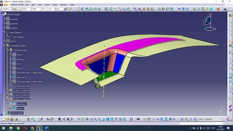
Then I have looked possible irregularities on sharp edges but all looked just fine.
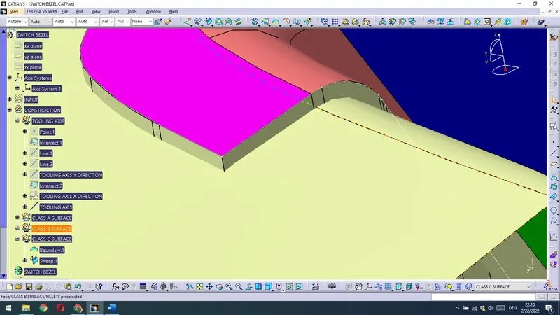
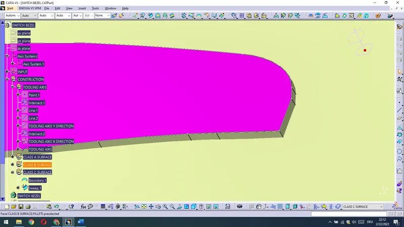
Splendid,now I have inserted new Geometrical Set under CONSTRUCTION and named it as SWITCH BEZEL and there I have joined CLASS A SURFACE and CLASS C SURFACE.
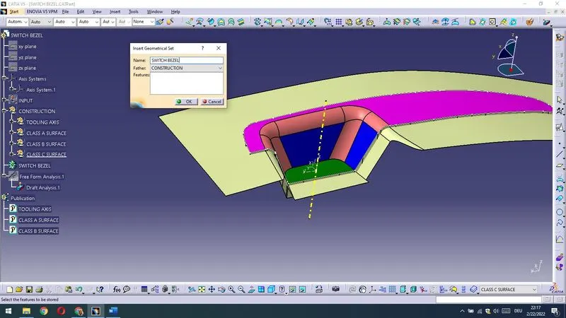
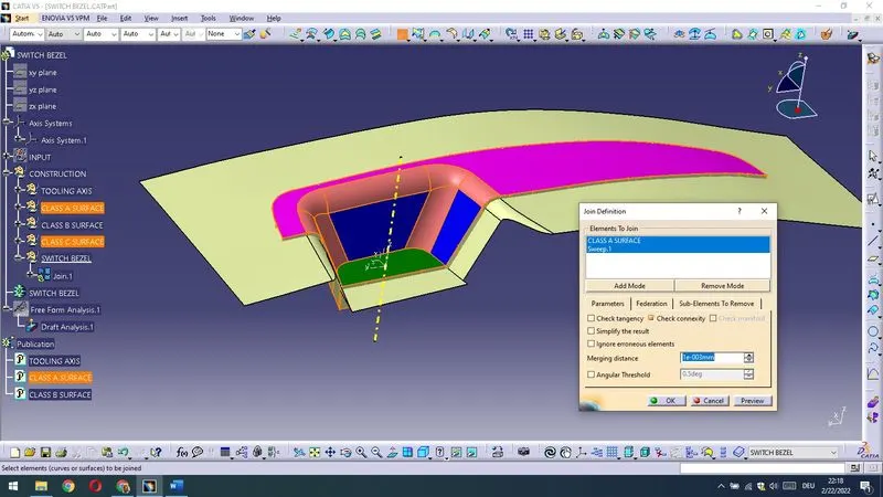
It is joined.
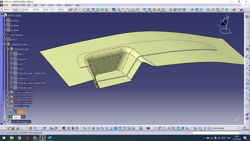
Then I have trimed it with CLASS B SURFACE and got closed surface as a final Surface shape.
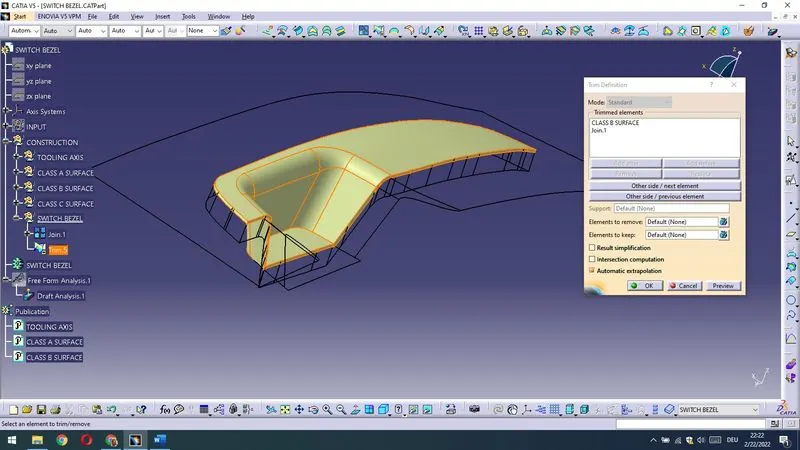
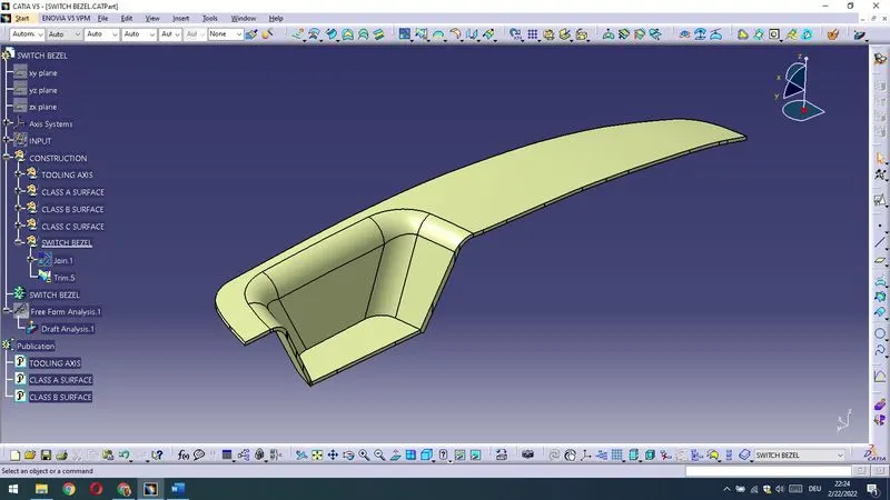
Finally with a Closed Surface option in the Part Design I will make a closed finished Part.
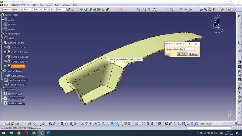
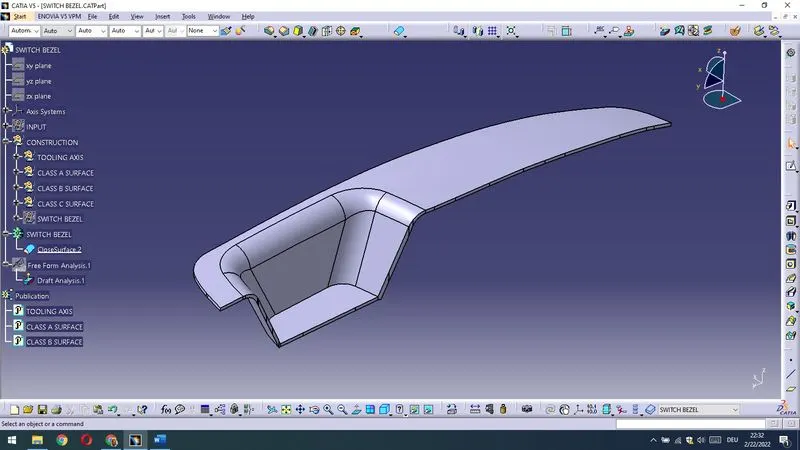
I have published CLOSE C SURFACE also and a make a Draft Analysis on the Part.
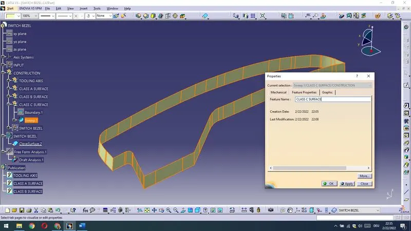
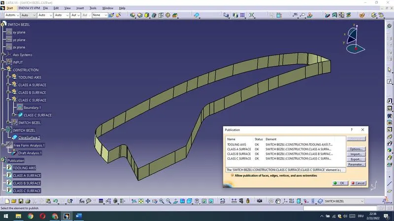
Now,on the end – Draft Analysis of the Part.
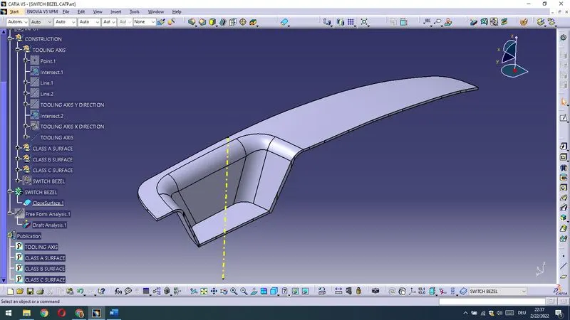
As done before – click on Draft Analysis comand and I am getting as it is shown bellow
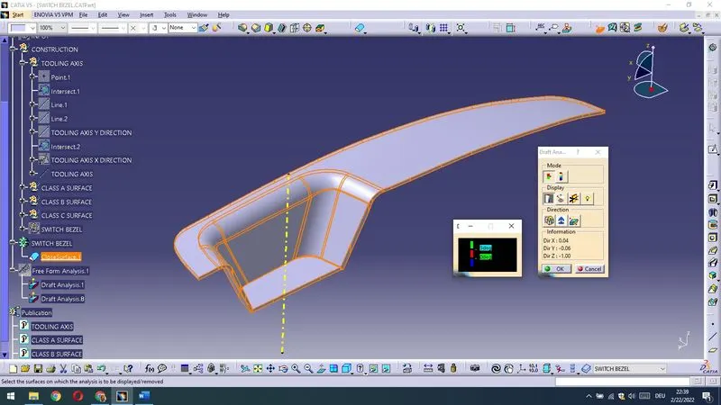
Then I have moved the compas on the TOOLING AXIS and lock the compas.
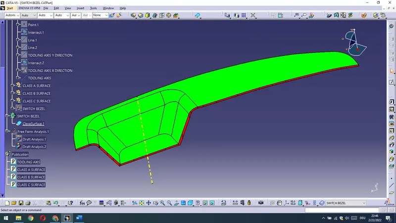
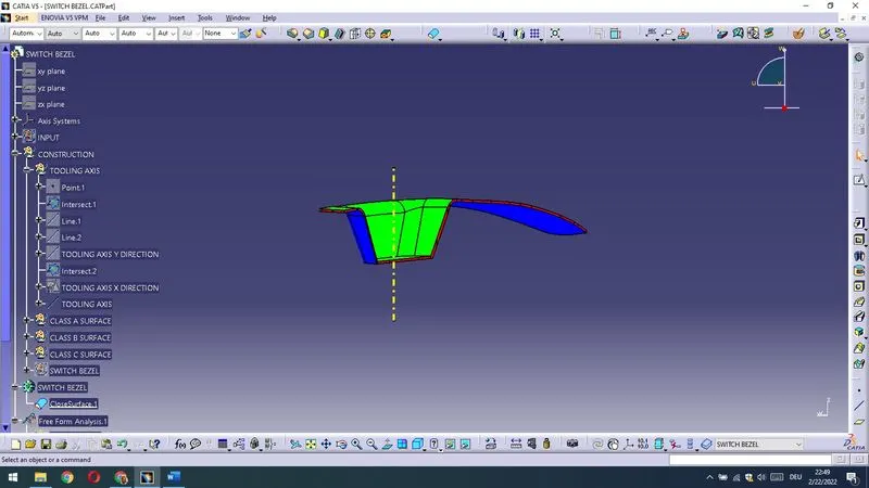
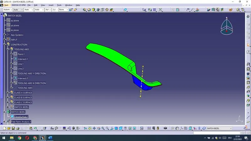
Then the Result is all surfaces above are green – the Part is manufacturable and ready for production.
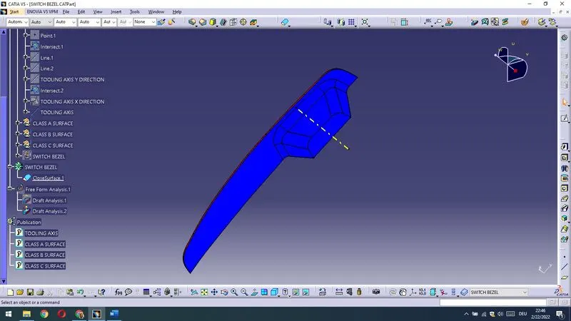
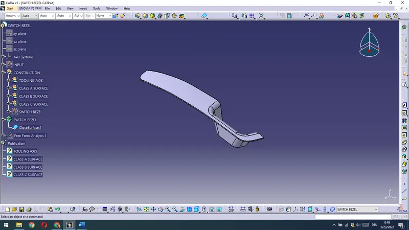
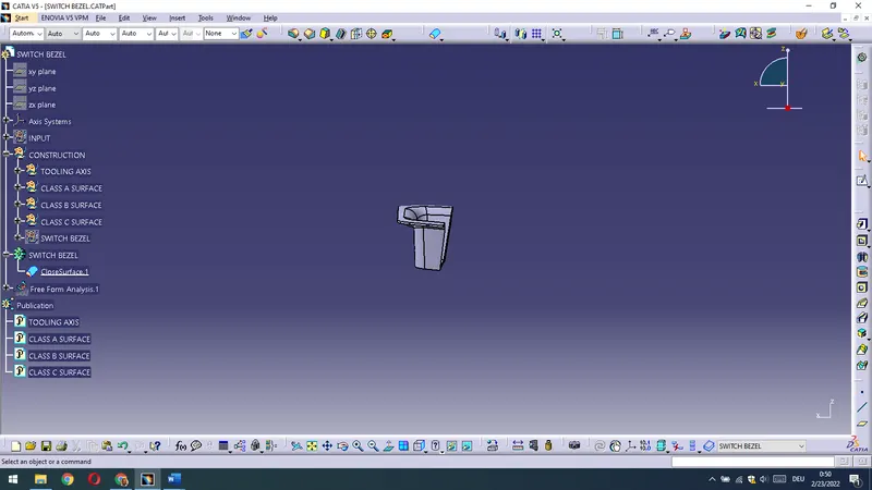
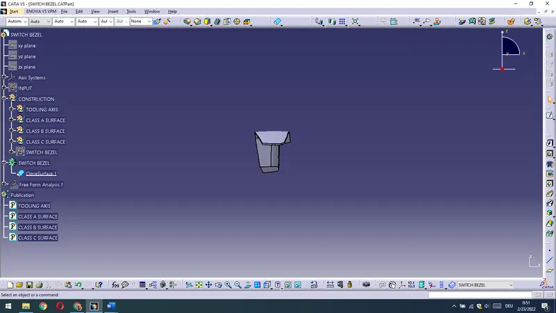
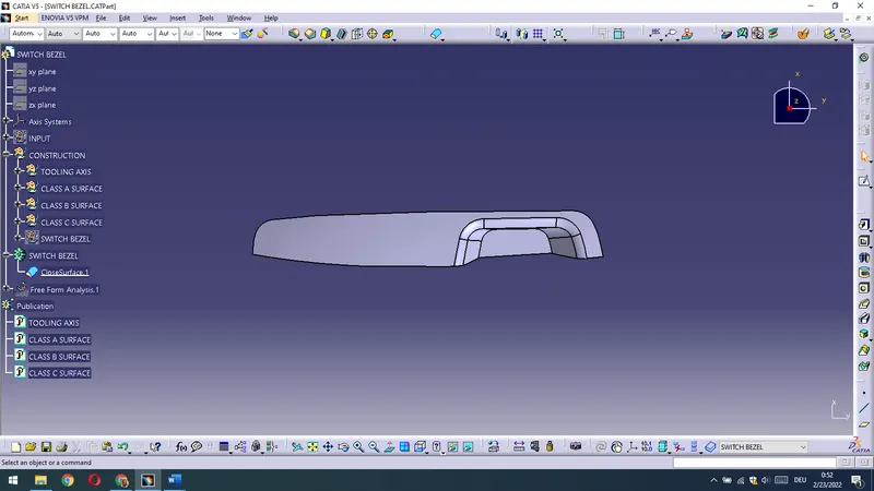
The Views Top,Side,Front and Botttom are given bellow (Isometric is already up).
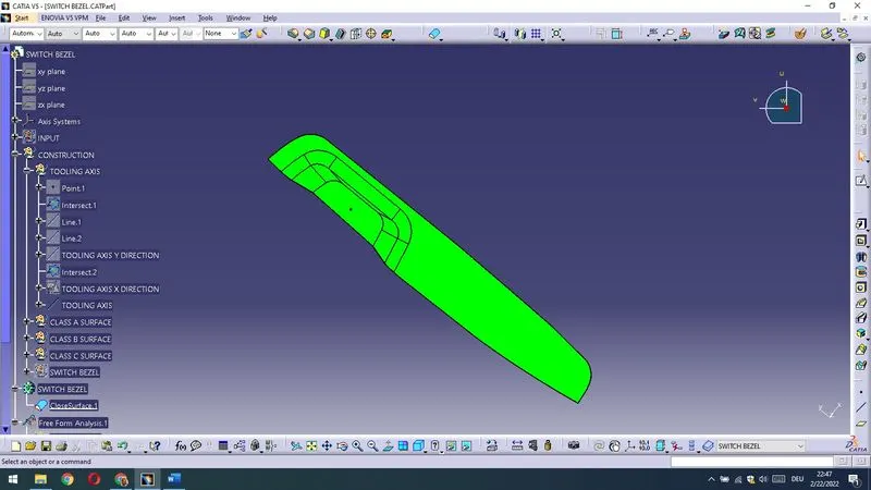
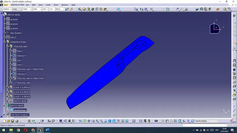
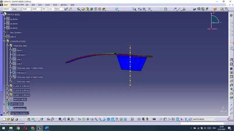
Bellow are Part Views:
Isometric View
Front View
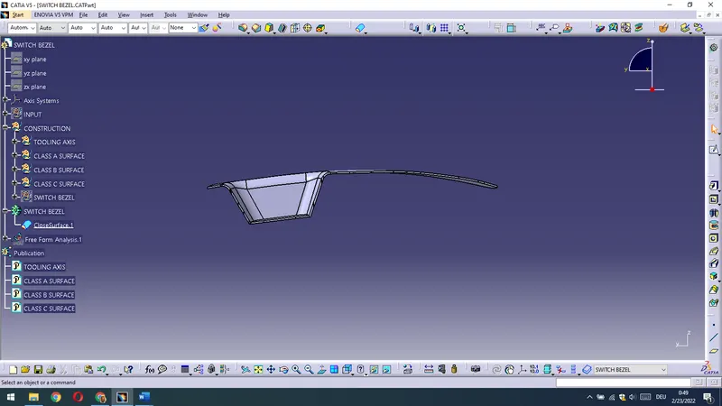
Side Views
Top View

Bottom view
That's all folks.
Kind regards,
Ivan Tole