Week 8 - Challenge 4 - Coin Holder Design
Hi fellows,
At first I have opened a Part and looked over it where I can put a tooling axis – I have decided on the bottom of the part in the middle.
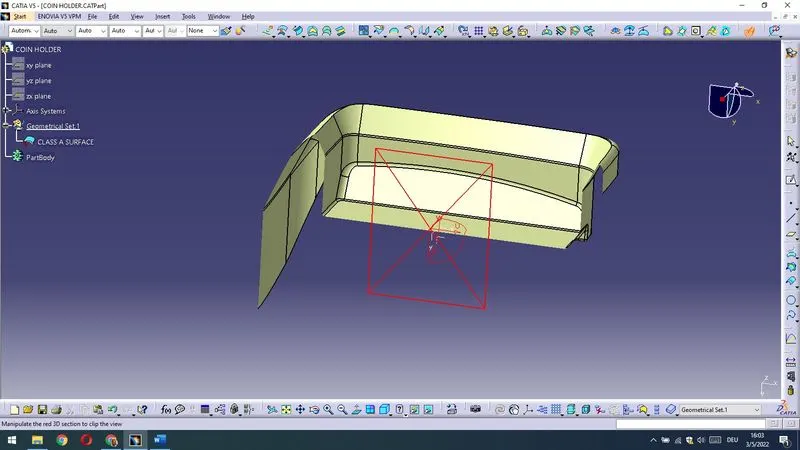
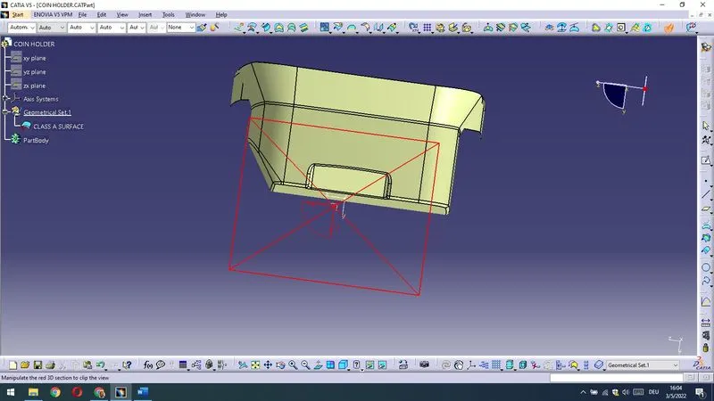
As it can be seen – side walls are cca.90deg regarding bottom of the Part – but with so given CLASS A SURFACE there is nothing else to do – I will suggest to make a improvement with a CLASS A SURFACE and make a Side walls with a bigger draft at aproximately 3deg.So,now I am renaming given Geometrical Set as INPUT and I am inserting Geometrical Set CONSTRUCTION and under it – TOOLING AXIS,CLASS A SURFACE (there I will paste CLASS A SURFACE from INPUT), CLASS B SURFACE and a CLASS C SURFACE.
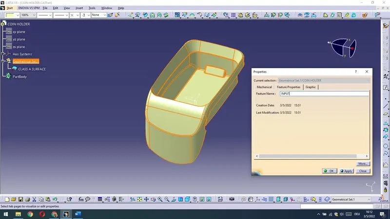
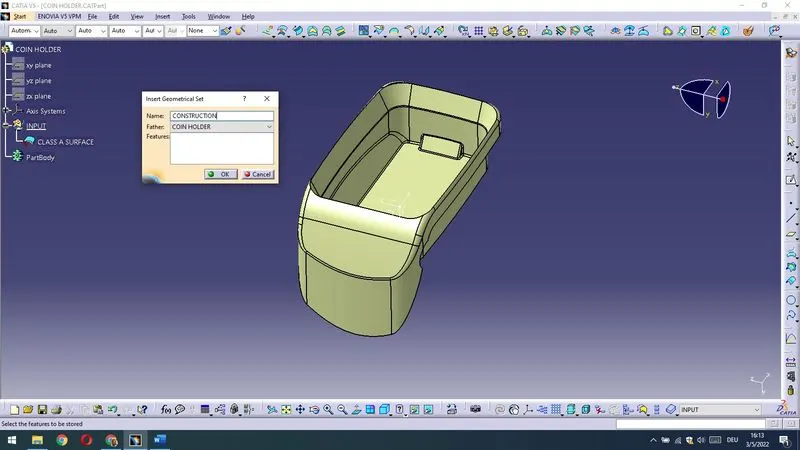
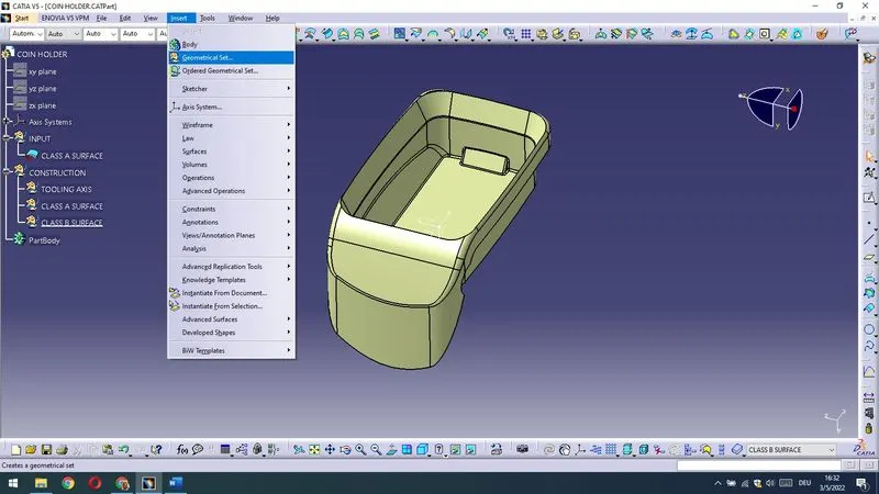
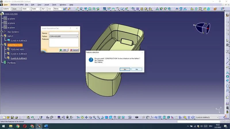
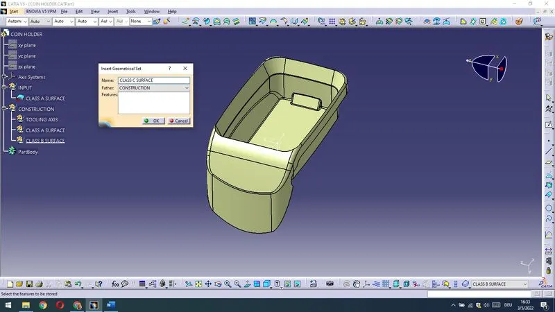
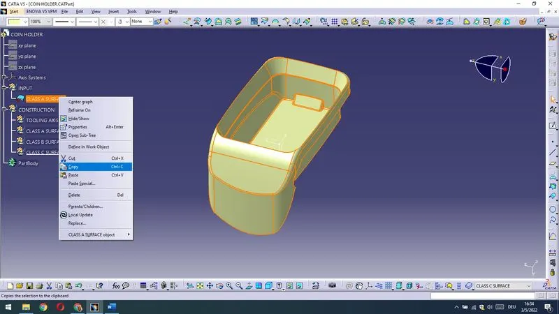
Then I have pasted CLASS A SURFACE from INPUT to CLASS A SURFACE under CONSTRUCTION Geometrical Set.
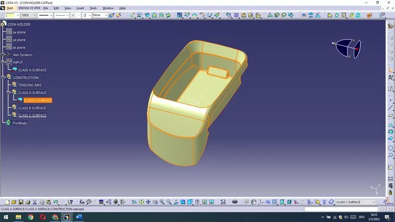
Now – I am creating a TOOLING AXIS as it is shown bellow.
In the middle of the bottom surface is given axis system and with it I am intersecting CLASS A SURFACE.
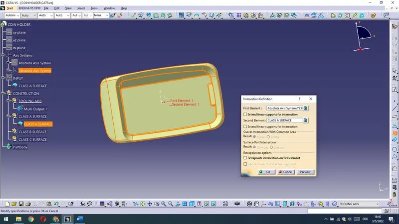
As it can be seen bellow – there is a problem with CLASS A SURFACE the angle with the plane in the middle,that is symmetric is always 0deg – CLASS A SURFACE should be modified and given with a draft on those surfaces (CLASS B SURFACE we could adjust and give with a draft but there is always problem with this part in core/cavity design and then the thickness of the part will be variable – that causes various,ununiform thickness of the part and this is a problem during molding and solidifying of the part).
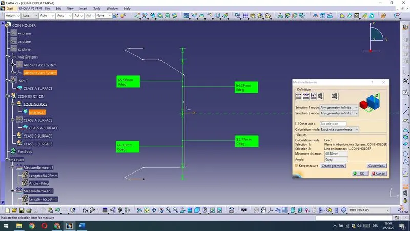
With so given Input,as a acceptable solution,I am drawing TOOLING AXIS in the origin point of Axis system normal on bottom surface.
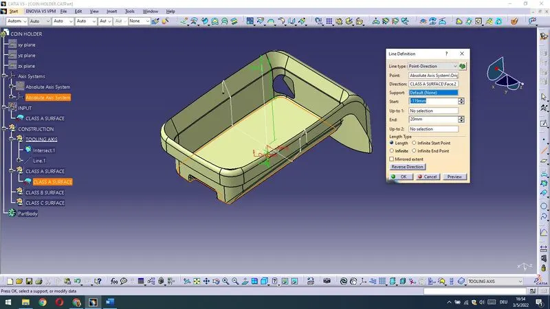
Now I am renaming the line as a TOOLING AXIS and changing its properties.
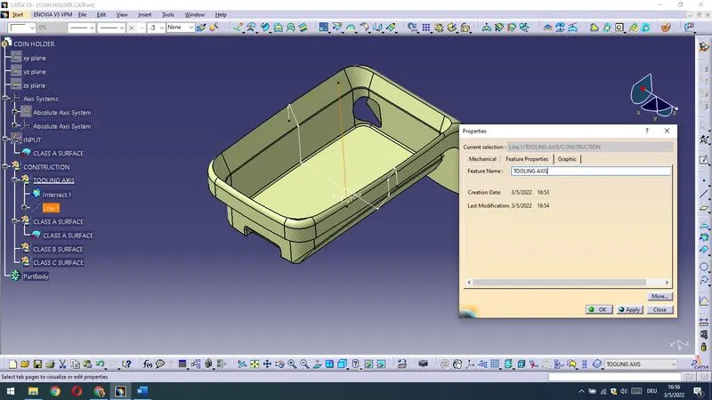
I have also published TOOLING AXIS.
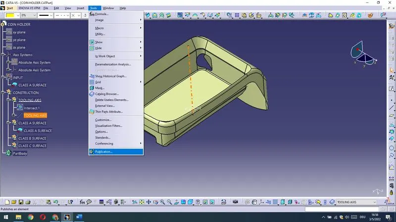
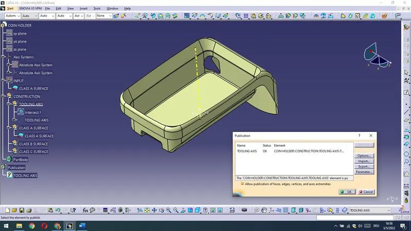
Draft Analysis with such Input (as I have already said,with CLASS A SURFACE so given) gives a result as bellow.
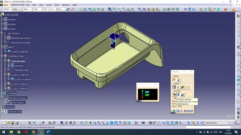
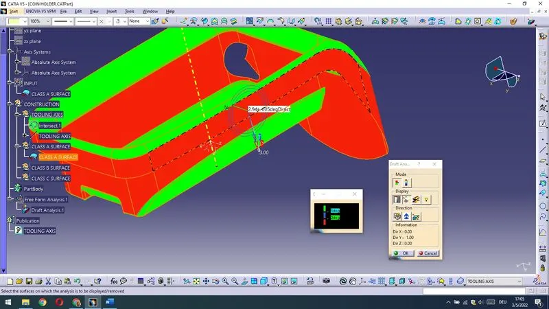
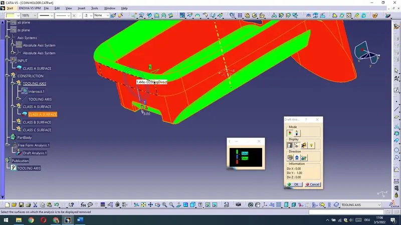
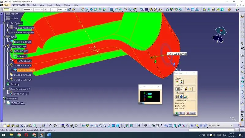
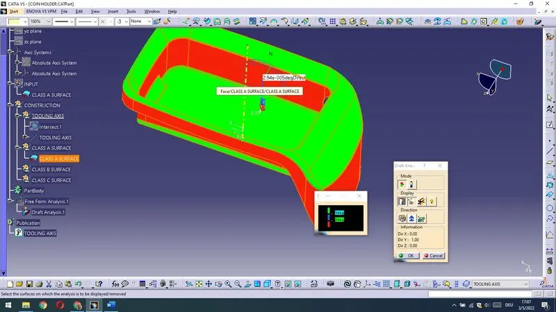
My suggestion as previoulsly said – CLASS A SURFACE should be corrected.I am not allowed,so I am moving forward with so given.I am publishing also CLASS A SURFACE.
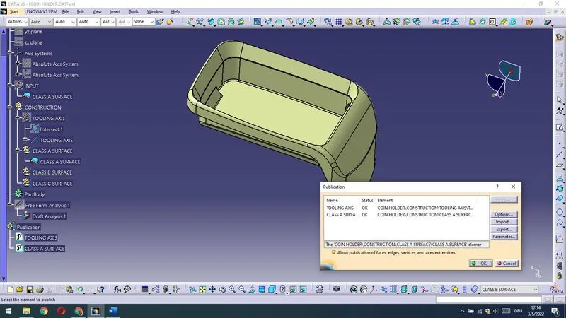
I am going to construct CLASS B SURFACE and therefore under that Geometrical Set I am inserting new Geometrical Sets – SIDE WALLS,OUTER WALLS,BOTTOM WALLS.
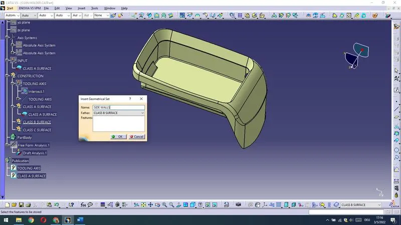
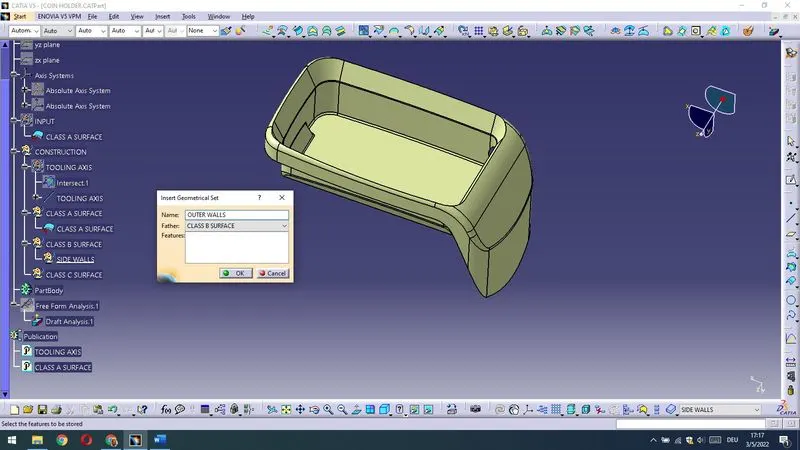
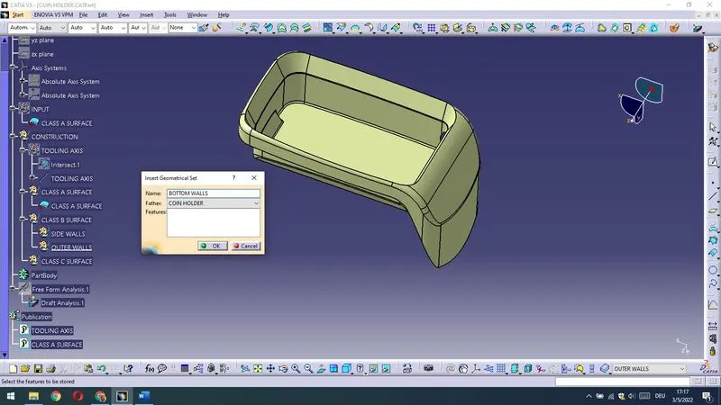
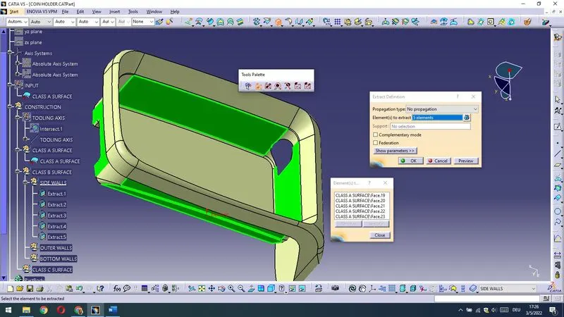
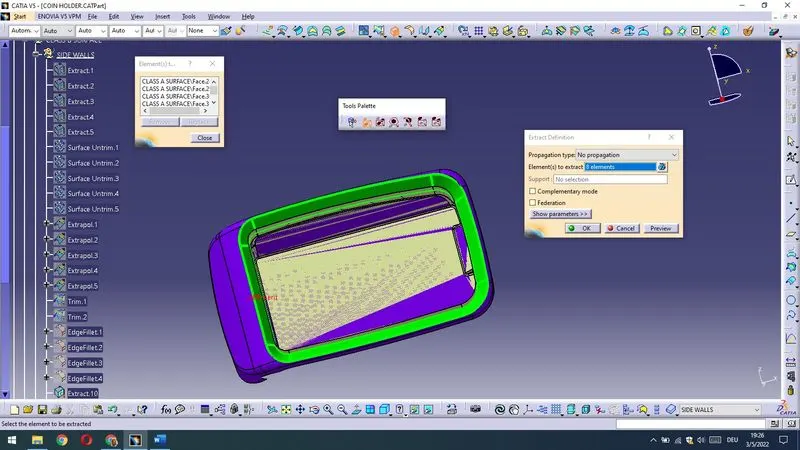
Now under Geometrical Set SIDE WALLS I am going to extract side walls as shown.
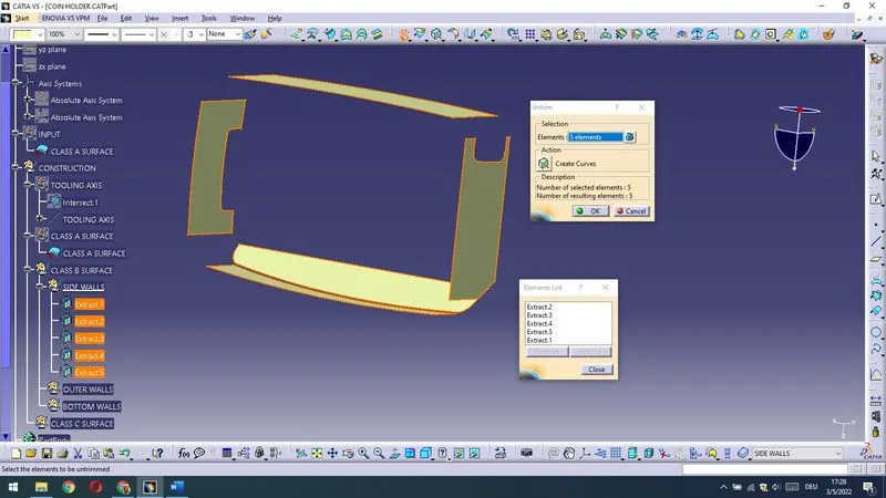
Then I am going to untrim extracted surfaces.
And then extrapolate them.
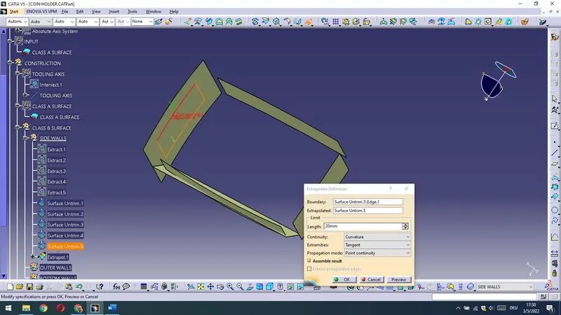
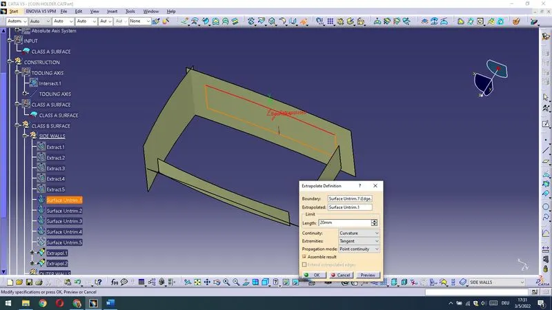
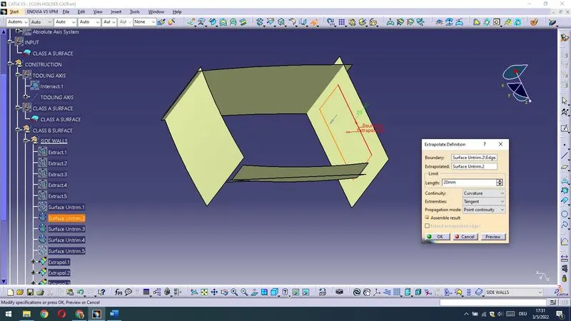
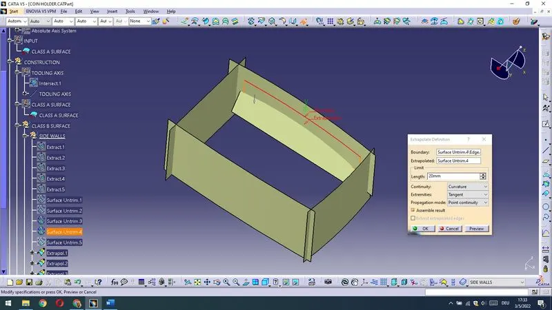
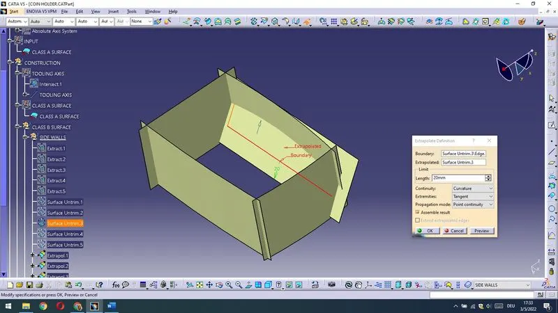
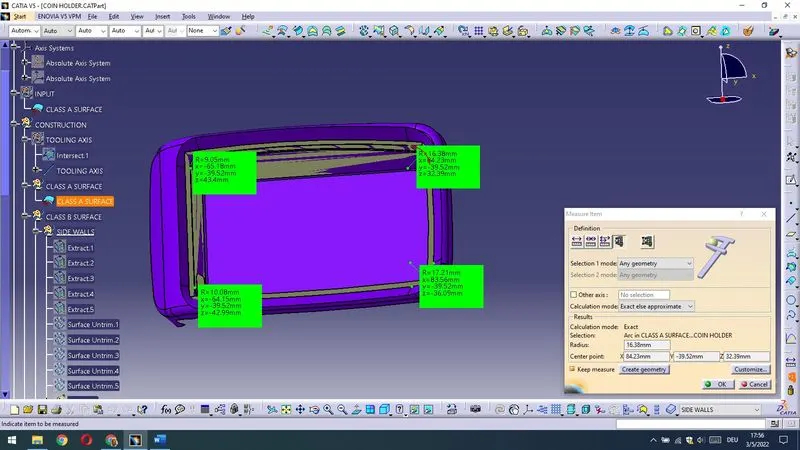
I have changed properties of the CLASS A SURFACE in order to be able to measure and compare it with that what I am doing,to get a better overview.
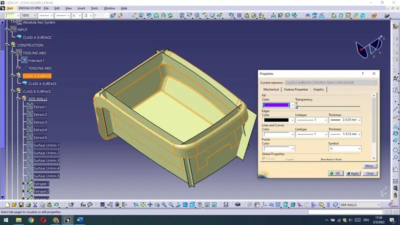
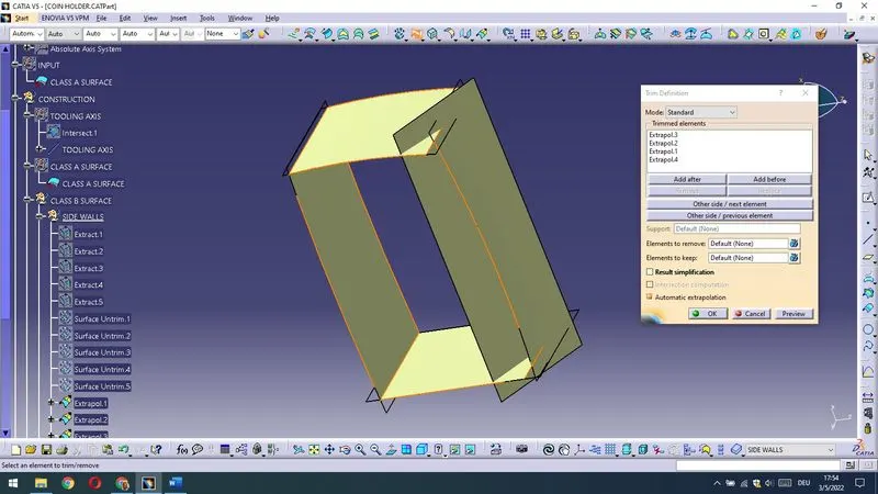
Then,I am trimming those surfaces.
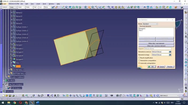
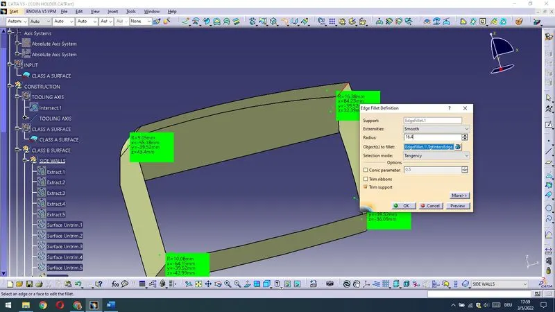
Fillets in the angles are.
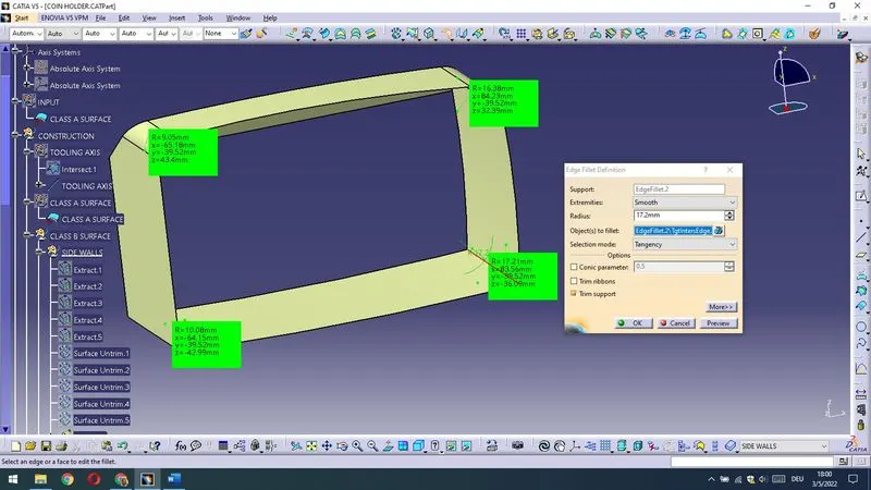
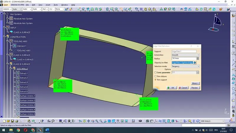
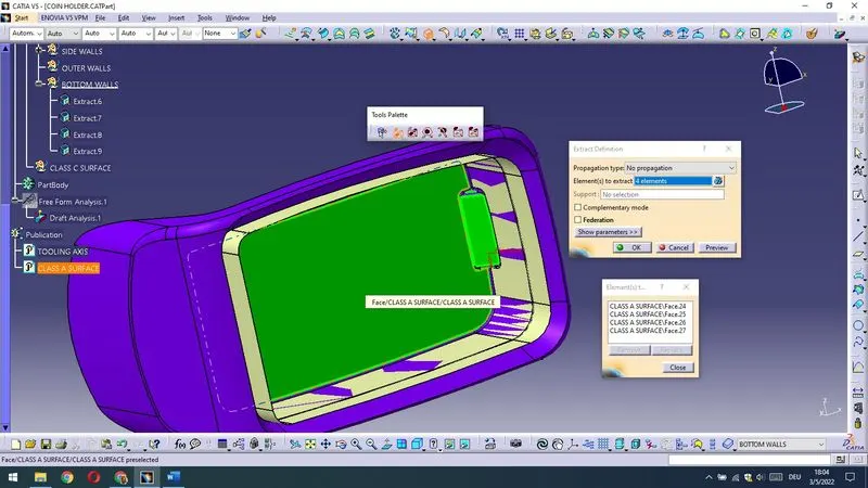
Now I am extracting bottom surfaces.
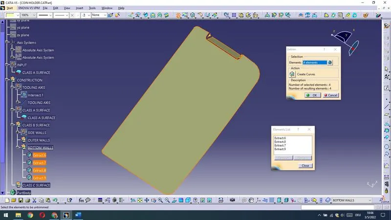
Now comes untrim.
And extrapolate.
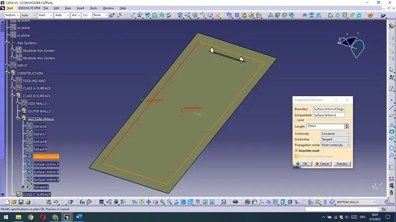
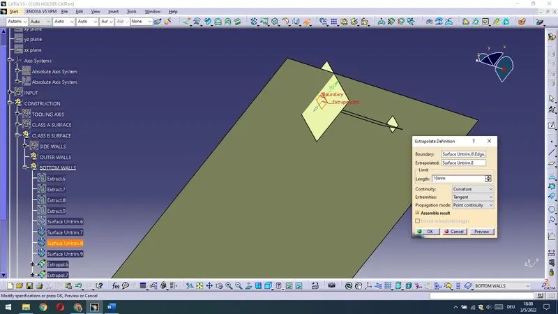
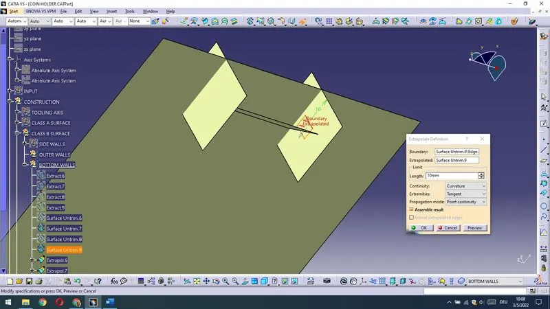
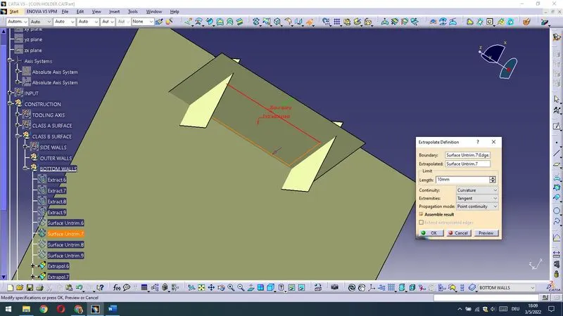
Now comes split and trim.
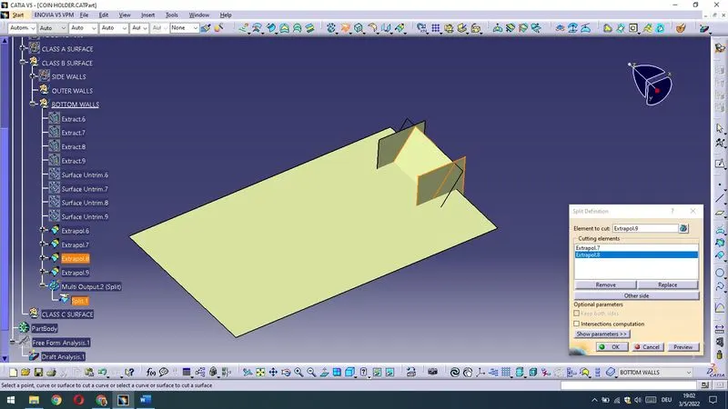
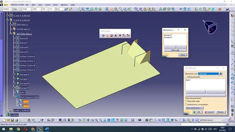
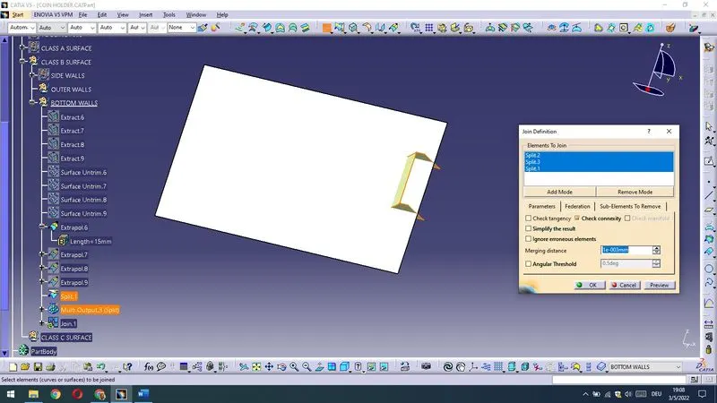
I have to join those splits.
And now comes trim.
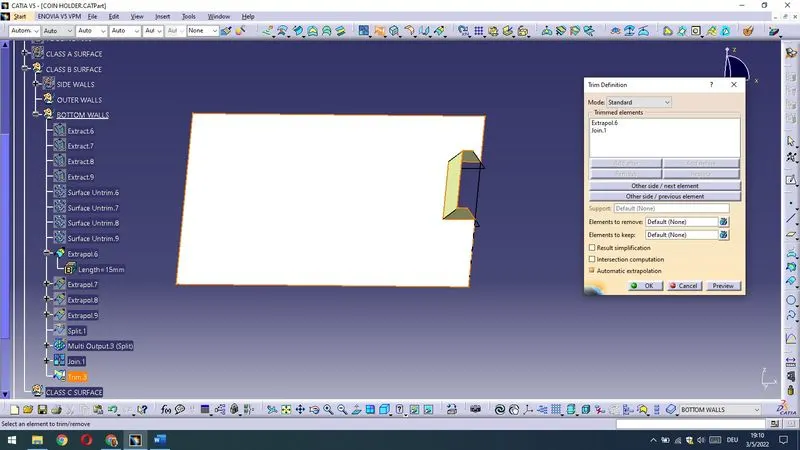
Now is time to trim BOTTOM WALLS and SIDE WALLS.
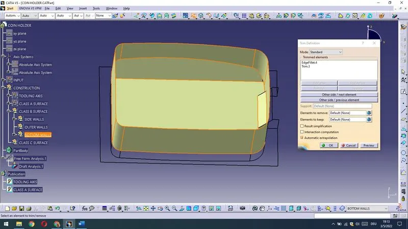
Now I am extracting side surfaces up on the Part.
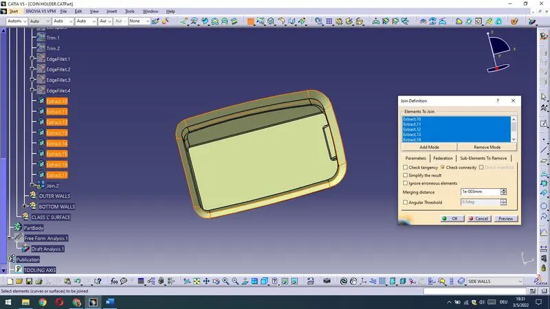
I have joined extracted surfaces,extrapolated and trimed it.
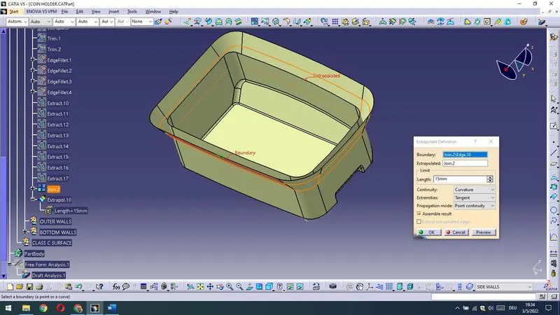
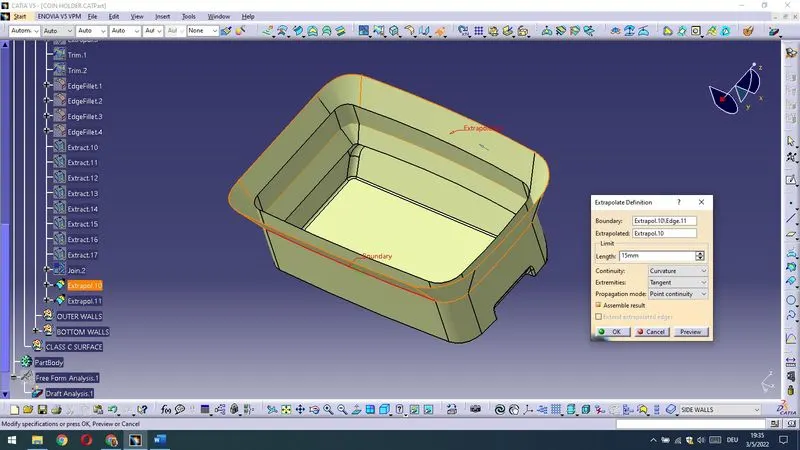
Now it is trimmed and filleted.
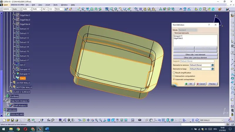
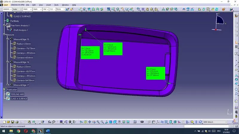
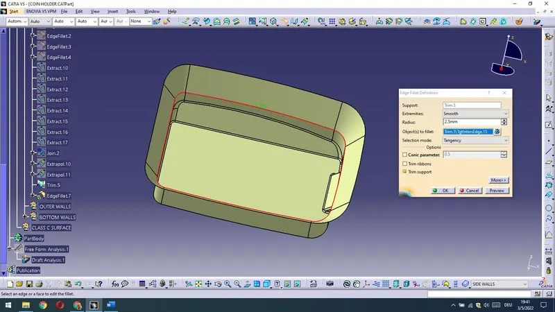
Now I am extracting outer surfaces.
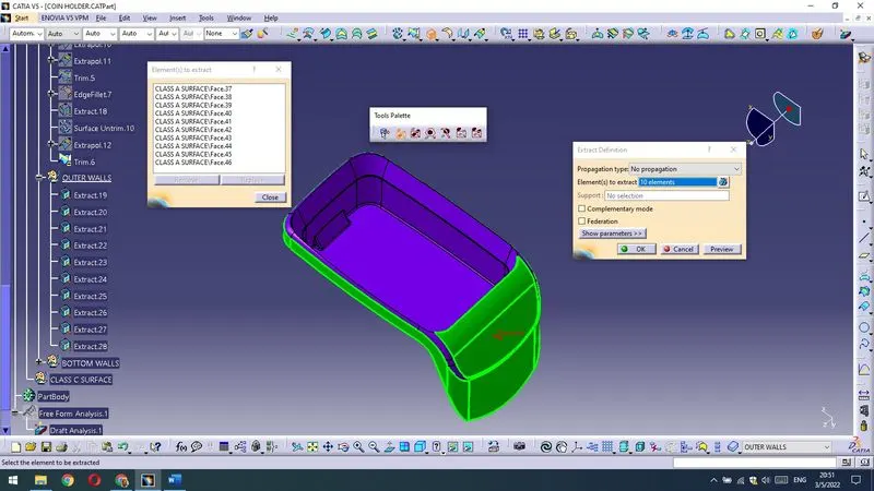
Then,I am joining and extrapolating extracted surfaces.
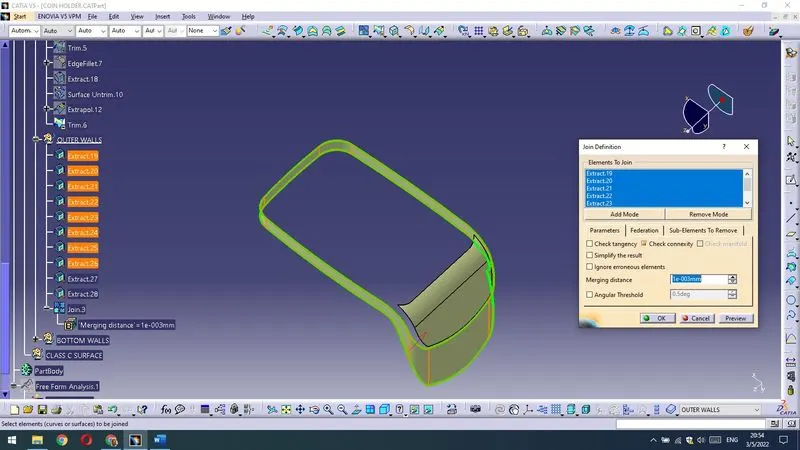
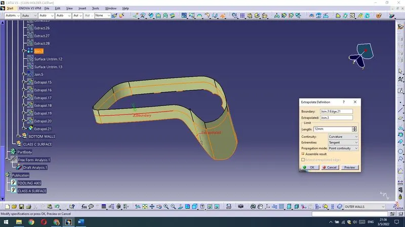
Now I have untrimed,extrapolated and joined also those surfaces.
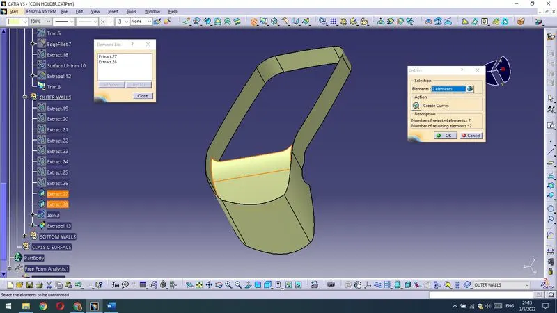
Then extrapolate.
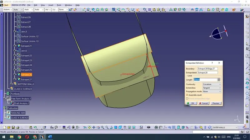
And trim.
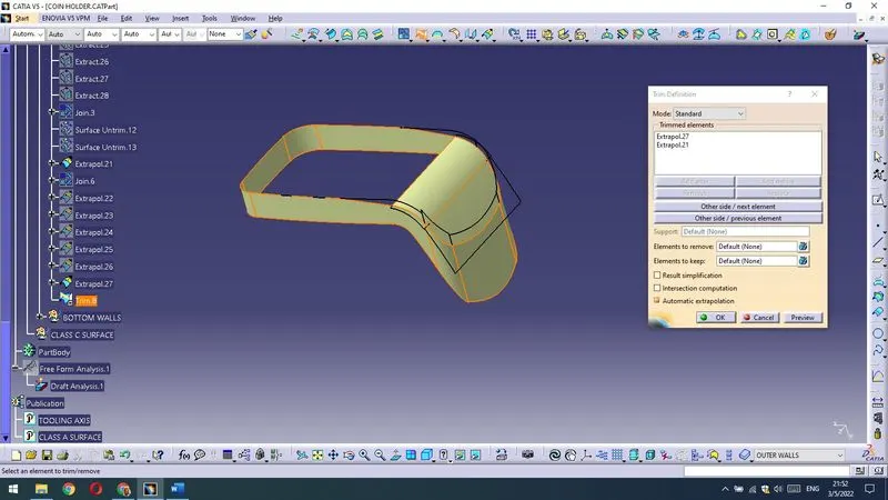
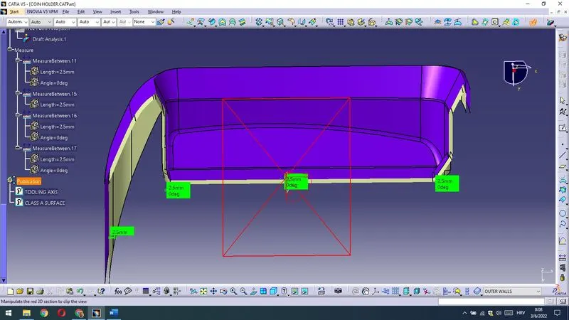
Then I have changed properties of those surfaces and offseted it for a 2.5mm as it is shown bellow.
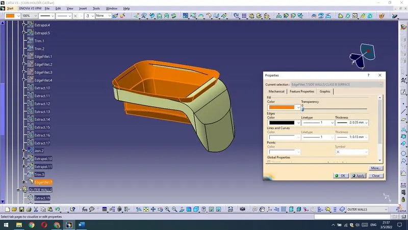
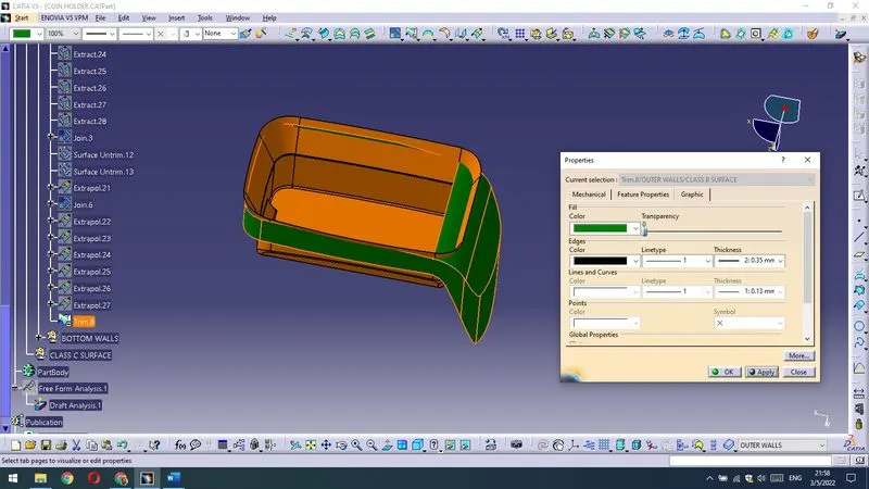
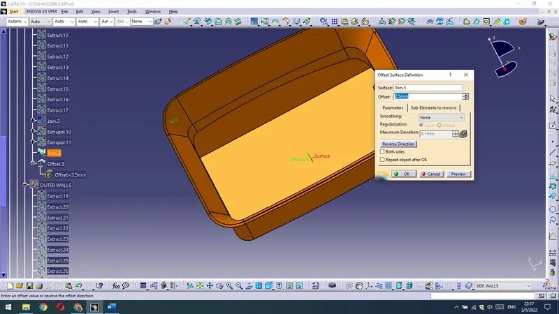
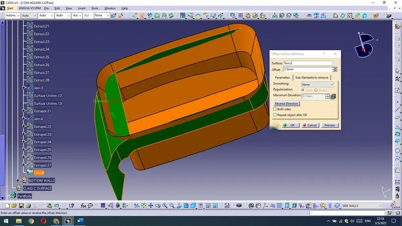
Outer surfaces are also offseted.
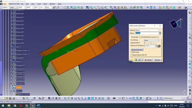
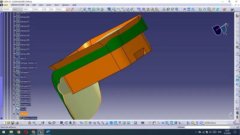
After changing colours of the offseted surface I am going to trim them.
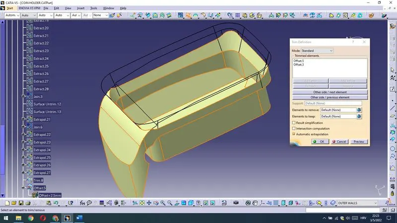
As a check I am comparated CLASS A SURFACE and a CLASS B SURFACE – it should be offseted for a 2.5mm.
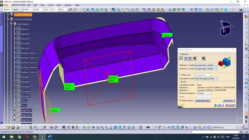
It is good – there is only one sufarce of the SURFACE B CLASS that goes above SURFACE A CLASS left.First I am extracting little surface that goes above CLASS A SURFACE – then untrim it,extrapolate and offset for a 2.5mm.
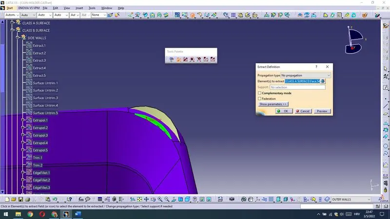
It goes untrim.
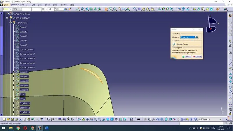
Then extrapolate.
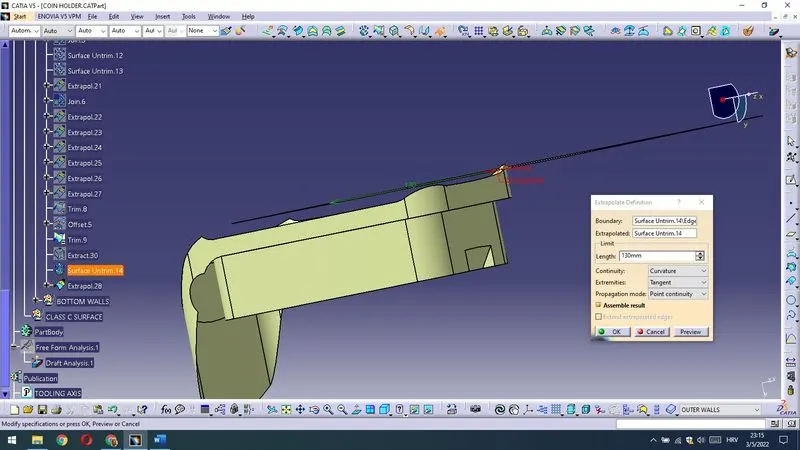
Now I have offseted and trimed it.
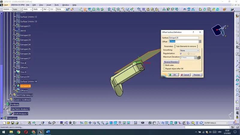
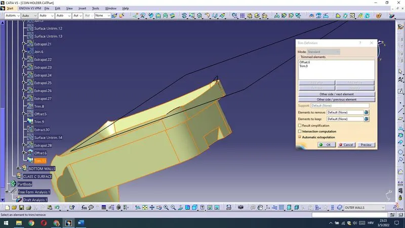
Now I will give fillets to the part regarding offset of 2.5mm inwards or outwards.
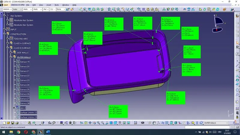

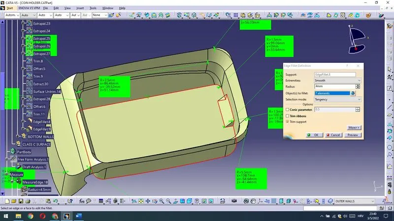
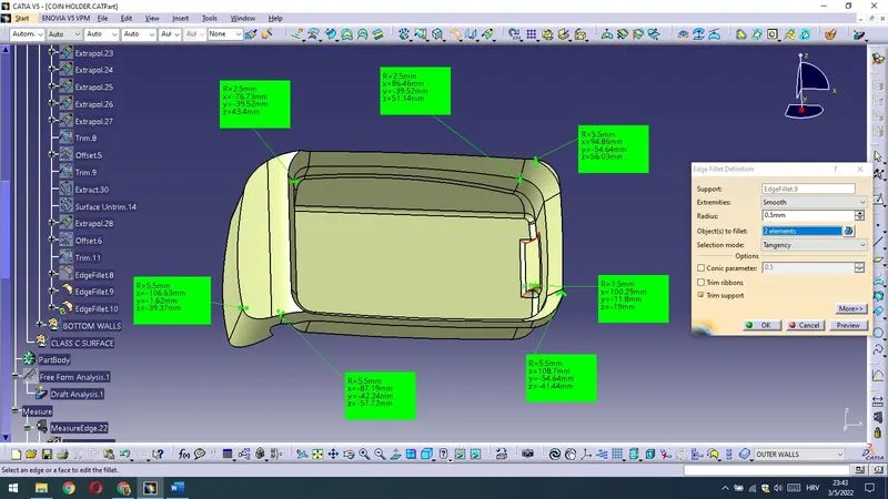
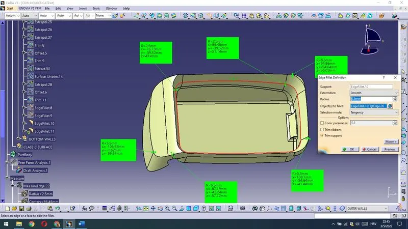
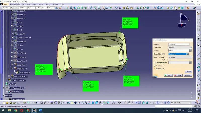
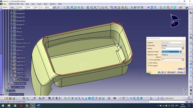
Final look of CLASS B SURFACE.
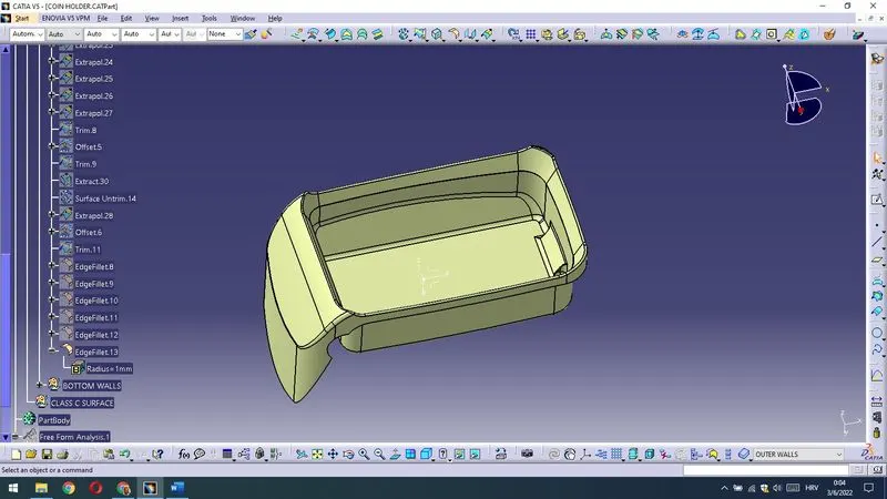
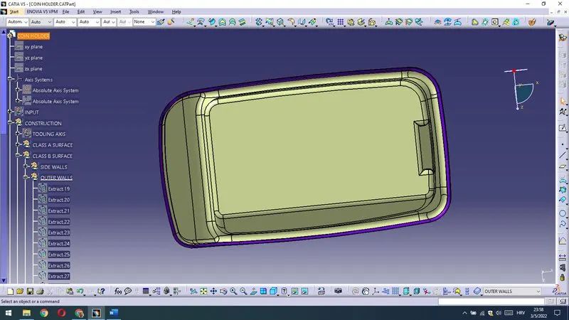
Final check of the CLASS A SURFACE and a CLASS B SURFACE comparating one with other.
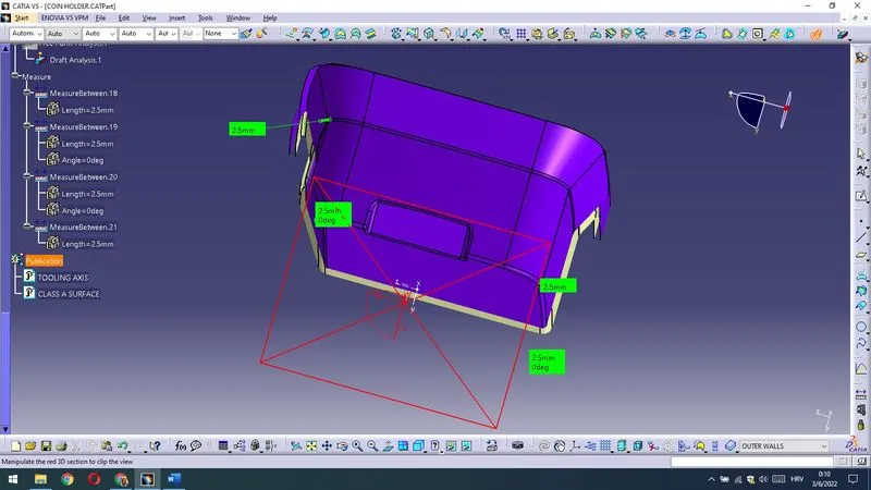
Now I am going to construct CLASS C SURFACE in order to get a closed surface.For that purpose I will do a sweep on the CLASS A SURFACE as shown bellow.
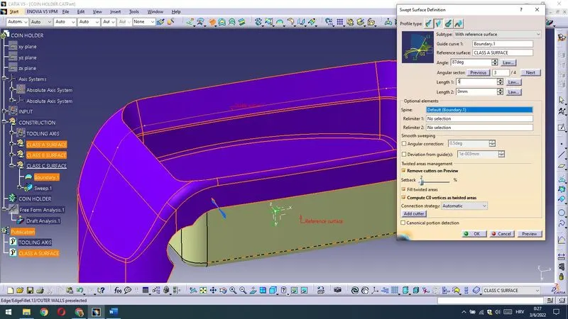
Now I am going to join CLASS A SURFACE and a CLASS C SURFACE and that Join is going to be trimed with CLASS B SURFACE.
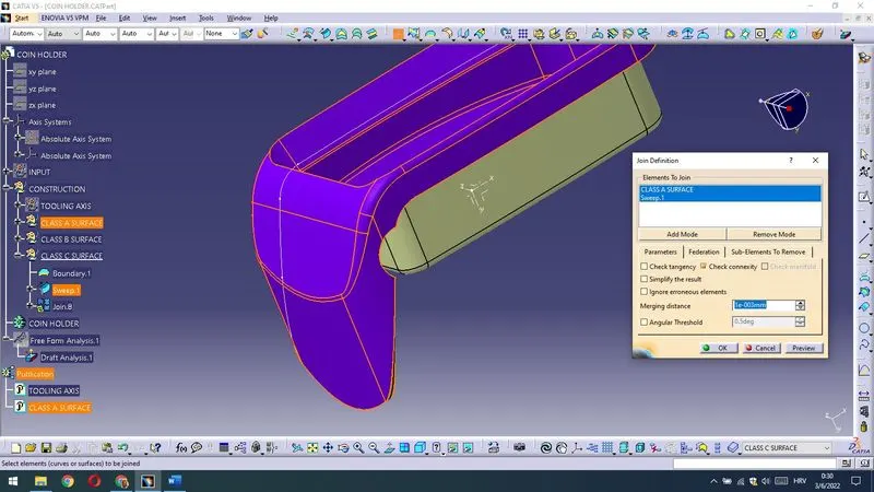
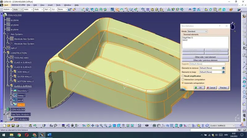
It is left to make a open space - pocket in the SIDE WALL as shown bellow.
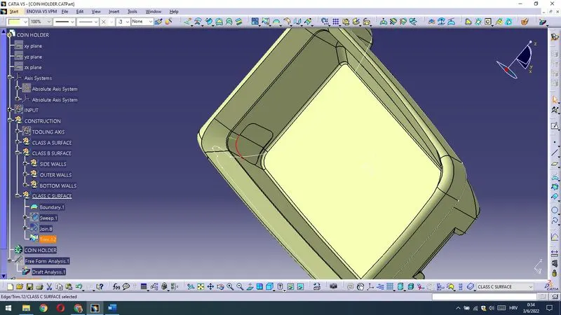
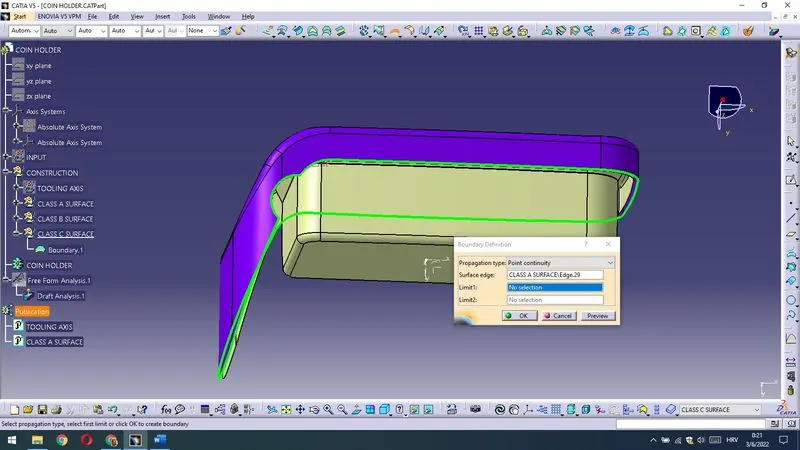
Then I have extracted neighbouring surfaces to get a boundary for SURFACE C CLASS.
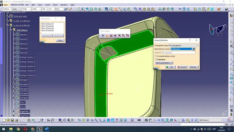
Then I have joined those extracted surfaces and made a sweep as previously.
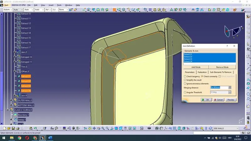
I am making now boundary of the extracted surfaces to have a guiding curve for sweep.
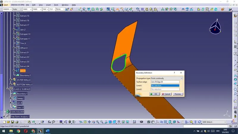
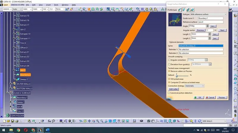
With it I have trimed rest of surfaces.
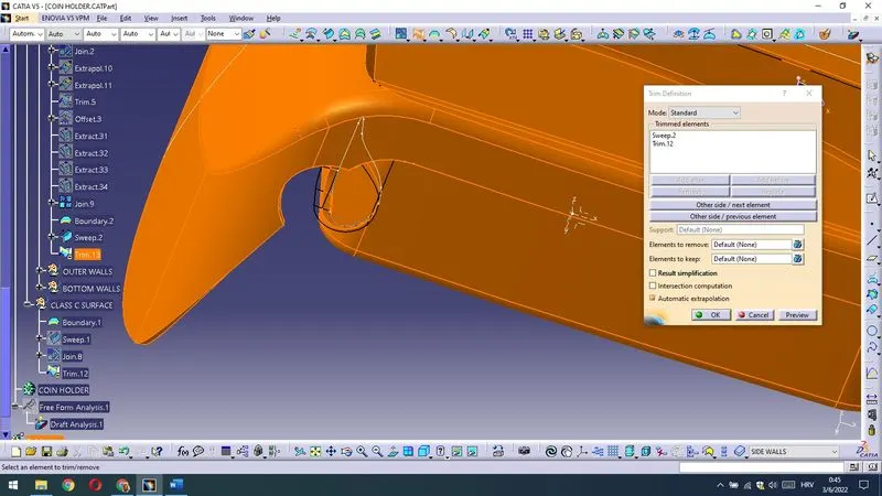
Now I have noticed a problem...drafting for a outer sweep is done inwards and it should be done outwards because of the parting line - that is why I should extend (extrapolate outer surface on OUTER WALLS).So,now I have extrapolate outwards surface to go down,bellow CLASS A SURFACE and then,I have joined that extrapolate with previous extrapolate.
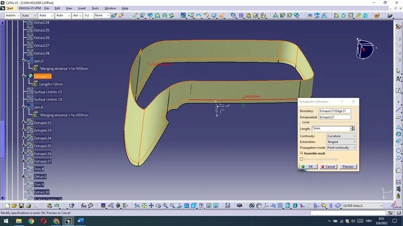
Then I have joined Extrapol.21 and Extrapol.29. and replace Extrapol.21 with that Join.
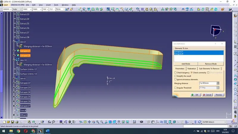
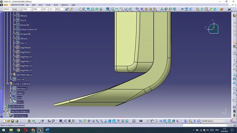
Now my CLASS B SURFACE looks better and I can change my Sweep outwards to get a better parting line and I can trim surfaces CLASS C SURFACE and a CLASS B SURFACE when Sweep goes outwards.
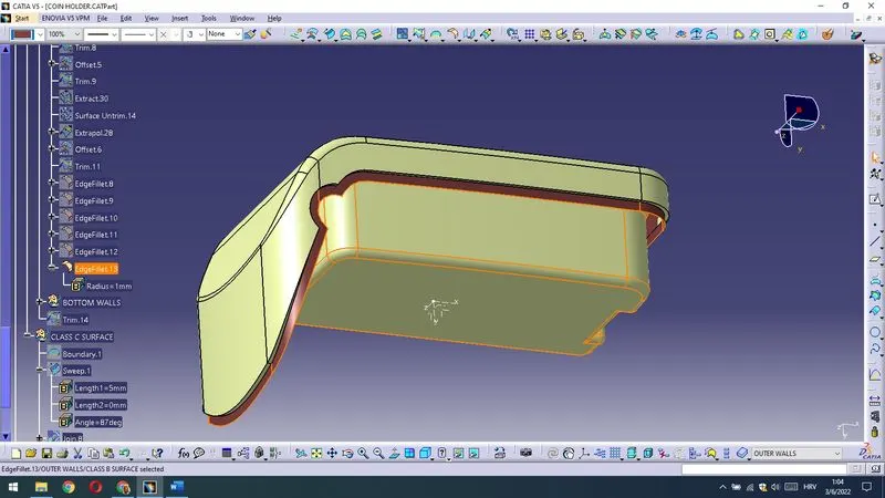
Now I am changing Sweep to outwards.
From
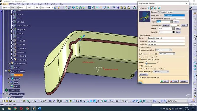
To
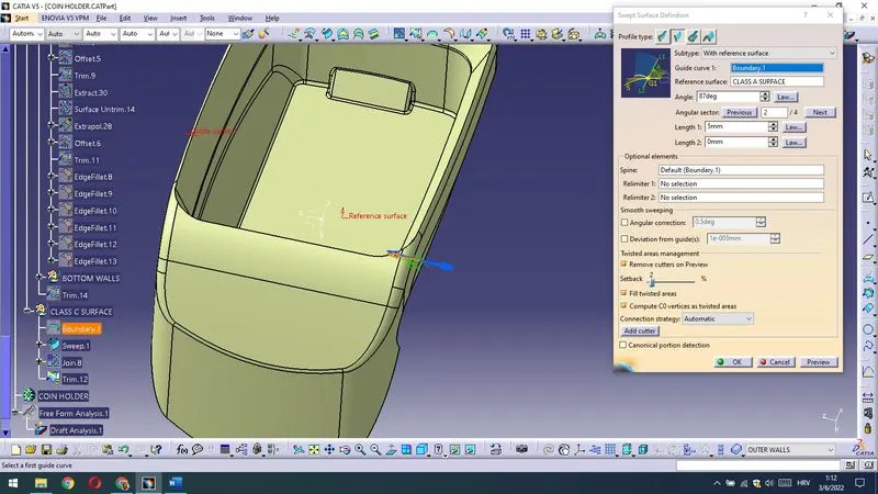
The result is shown bellow.
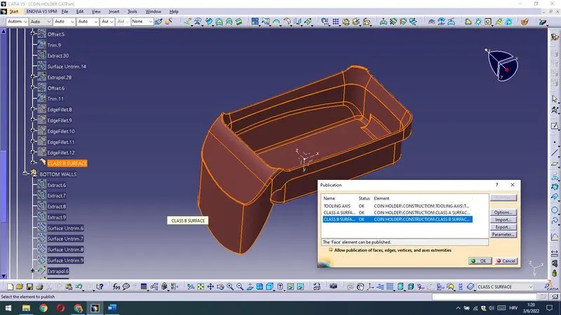
I am now publishing also CLASS B SURFACE and a CLASS C SURFACE.
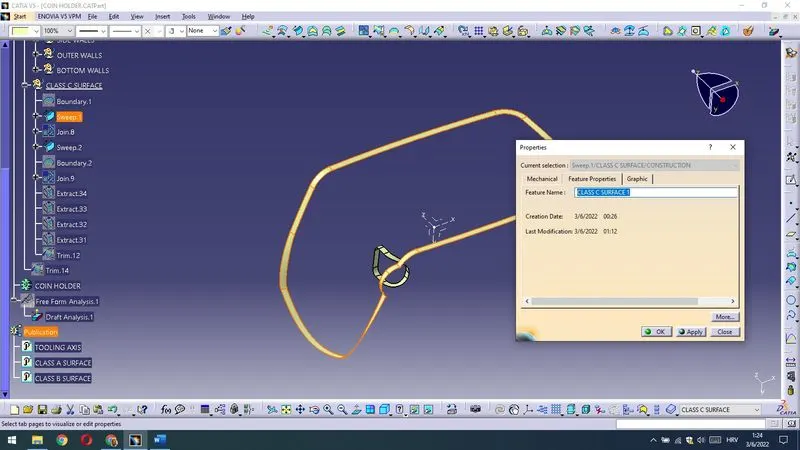
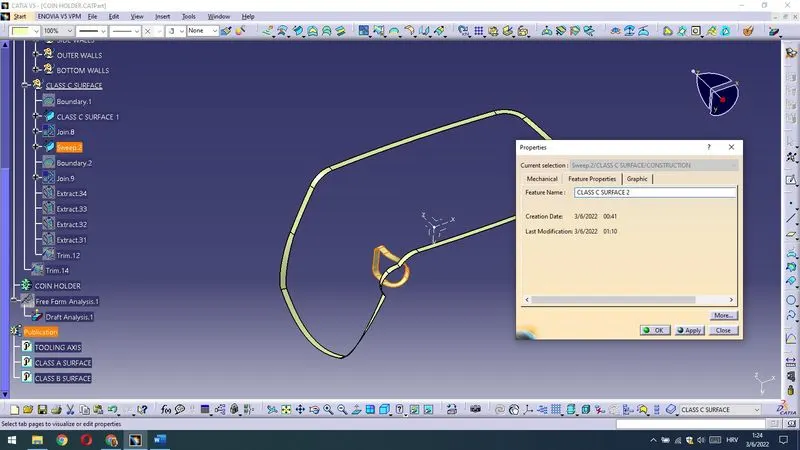
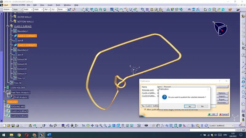
Now I am going to close COIN HOLDER surfaces.
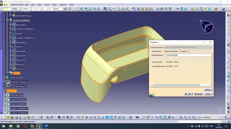
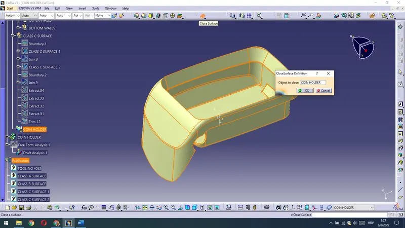
It is closed.Now on the end,I will make a final draft analysis on the model.
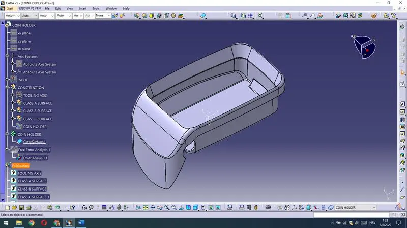
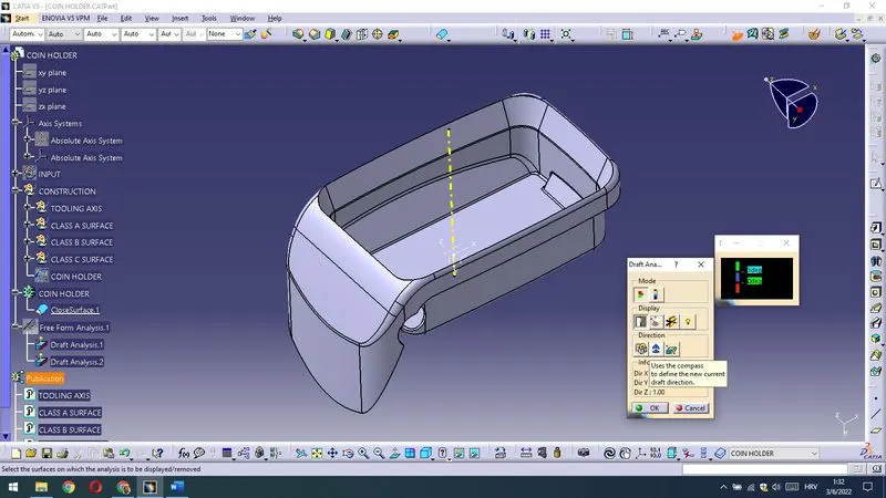
I have already made par remarks regarding CLASS A SURFACE,so after analysis is done,all above is green and down red,but as I already said some surfaces on the CLASS A SURFACE are made without draft and one get result as shown bellow.
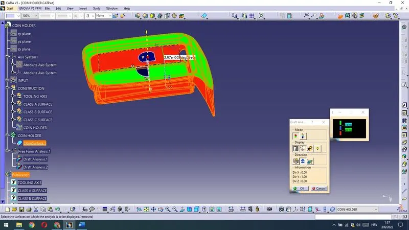
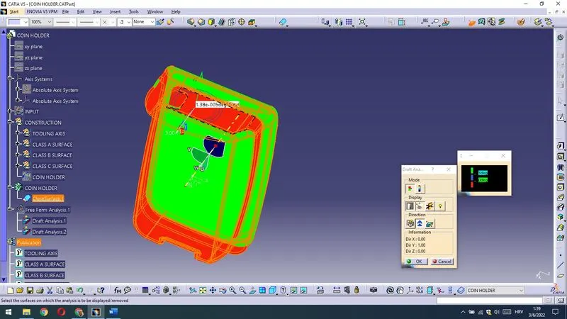
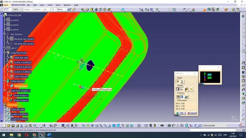
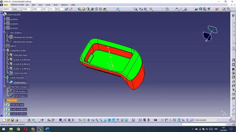
As a conclusion - CLASS A SURFACE should be corrected to get a manufacturable part.
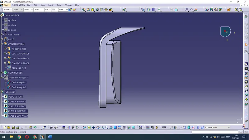
In this final section I will give vaious views of the constructed part COIN HOLDER.
Isometric view
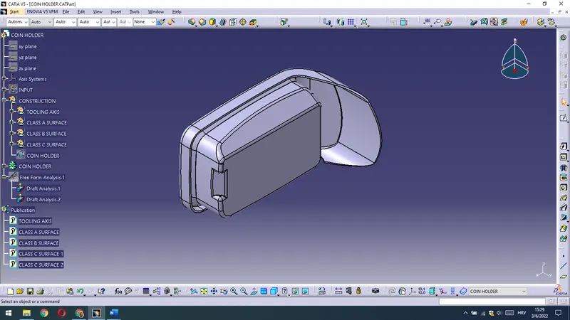
Front view
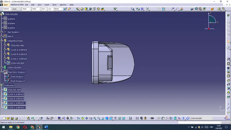
Side views
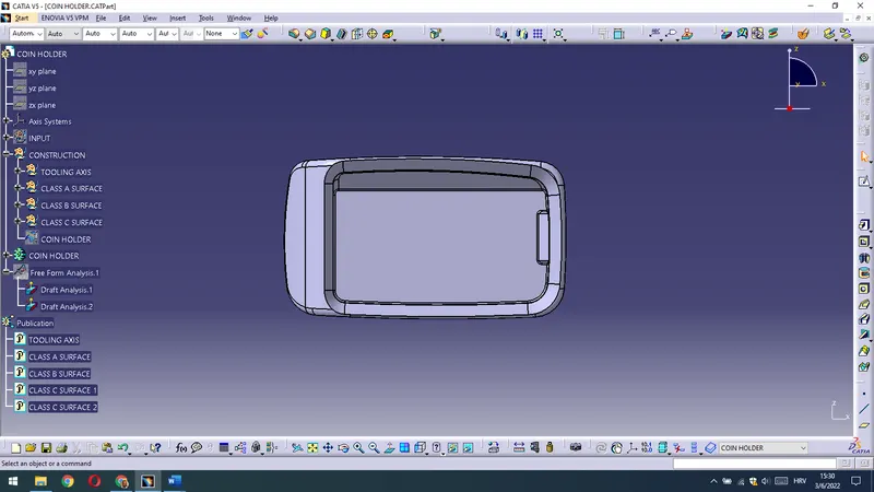
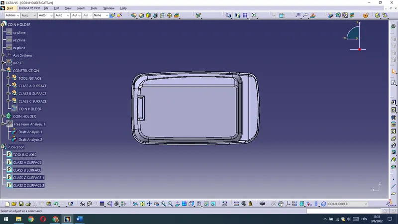
Top view
Best regards,
Ivan Tole