Week 9 - Project - Master Section Development
AIM:
To Design B-Pillar Through Master Section Development And Write a Detailed Report.
Given:
- A-Surface
Master Sections
Distance Between Ribs Should Be 50mm
B-Pillar
The B-Pillar Is The Central Pillar Of The Car. This Pillar Is Actually a Sheet Metal Part Which Is Welded In The Biw Of The Car. The B-Pillar trim Is Attached To The B-Pillar And Improves The Aesthetic Look Of The Car.
Mostly The Trims Are Manufactured By The Injection Molding Process. The Design Of The B-Pillar Is Carefully Done To Make The Part Manufacturable And Usable In The Interior.
While Manufacturing a Part Through Injection Molding a Lot Of Defects Can Occur On The Plastic Part Which Will Destroy The Look Of The Panel.
The Design Has To Made In Such a Way That All The Errors Can Be Rectified.
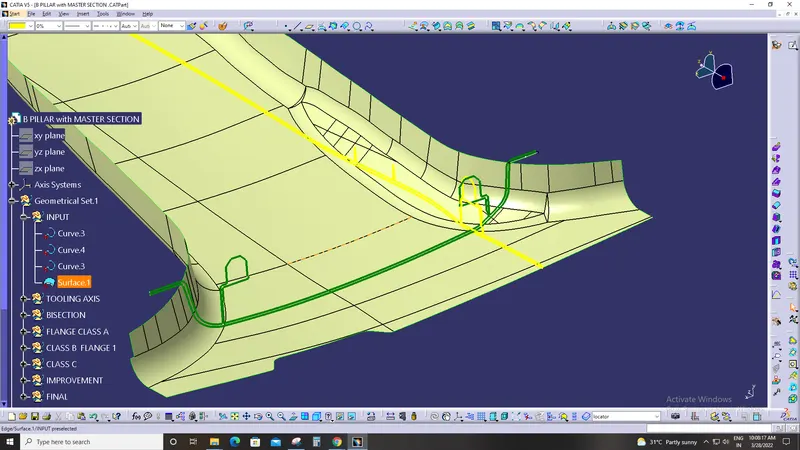
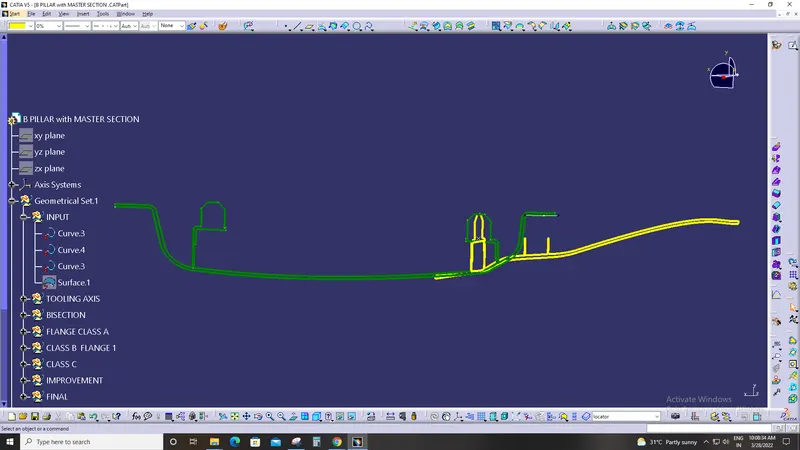
Master Section:
Master Sections Are The Guides For Design Requirements Which Shapes The Component After Technical Styling Of Class A Surfaces The Body Frame Is Mainly Composed Of Floor Longitudinal Beams, Upper Side Beams, Door Sill Beams, And Front Cover.
The Rear Beam A-Pillar, B-Pillar, C-Pillar And Other Load-Bearing Beam Structures Are Composed. Master Sections Are Parameterized Model Of The Vehicle Body That Outlines The Guide For Npd Team .
In This Report B Pillar Cover Creation With Detailed Procedures Of Surface Development And Attachement Features Are Covered Overview Design Life Cycle Automotive Industry The Stages Of Design Life Cycle Are
Concept Sketches:
Concept Sketches Are Rough Idea Of Free Hand Sketch Obtained Through Styling Team And Will Be Used To Prepare The Model.
It Is Usually Done Through Pen And Paper And Through The Painting Software. This Is Will Be Used To Generate The Concept For Preparing The Model By Incorporating Various Styles And Information Obtained Through The Stakeholders
-Class A Creation:
After Finalizing The Concept The Sketches Are Usually Worked In Software’s Such As Auto-Desk Alias To Create Class A Surface
 Clay Modeling :
The Class A Surface Is Concurrently Worked By Clay Modelers To Brainstorm And Benchmark The Styling Of The Product And Later. The Concept Is Validated By Bringing Up a Rough Clay Model And Then It Is Passed On To The Design Team For The Preparation Of New Product Design (Npd) Cad.
-Npd Cad:
This Where The Development Of Surfaces To Parts In Cad Kick Off And Design Engineers Involvement Is Vital In This Stage.
The Designers Will Work On The Input Class A Surfaces Which Are Validated From The Feasibility Team
The Procedure Followed In Creation Of The Plastic New Product Design
Tooling Axis
B Surface Creation- C Surface Creation
Closed Body Creation
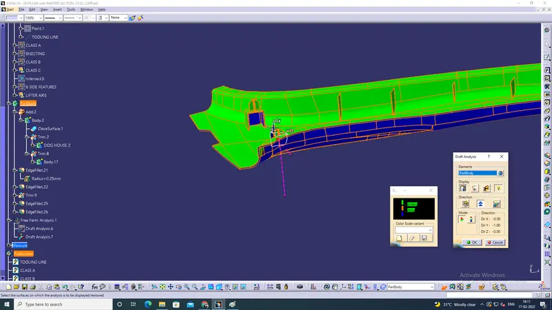
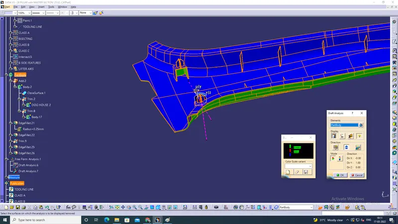
Draft Analysis
Tooling Axis:
The given class A Input Is Analyzed To The Part To Manufacture And Tooling Axis Or Tooling Direction Or Die Line Is The
Direction That Molds Pull Apart In Injection Molding. There Are Two Mold Pieces Names Core And Cavity. Thus Tooling Direction
Determines Mold Separation And Also Becomes Vital In Developing The Plastic Product Which Is Drafted To Desired Nominal Angle For feasible Clearance And Ejection Of Final Part From The Mold
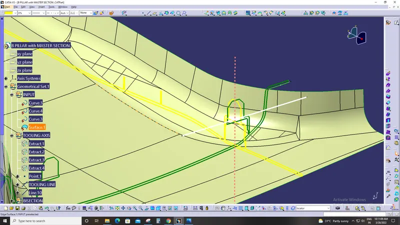
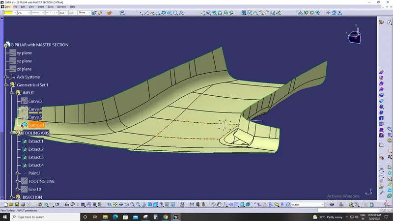
extract the master section and create the point of mid in the extract in the midpoint of o.5 and the point the create the verical line and that has the point axis for b pillar
CREATING FLANGE
When we observe the master-section properly, we will find the class-A has some projection outwards which is not in the input.
So we have to create these flanges on class-A on both the sides, taking master-section into consideration as it contains all the description of the flange.
Once we make flanges on both sides of the surface, we can offset it and trim with class-B surface too.
PROCEDURE FOR FLANGE
Extracting the respective boundary of class-A surface and then using smooth curve tool.
Sweeping this curve with the reference surface as class-A surface (make sure it is extending on both side of class-A, this will
reduce our time of creating extrapolate later).
We have to put different values for draft till the flange matches the master-section.
Once this is done, we get our flange. Offset it by 2mm downwards for class-B. Trim them with respective surface.
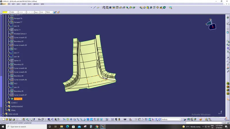
While making flange on one side we observed that the class-A surface and master section are not matching at one point. Here we made a flange as parallel to the master-section’s flange as possible and then made an offset (1) of that flange.
Later we trimmed it with the class-A surface. On this side the offset was our original flange, so for class-B we made an offset of this surface.
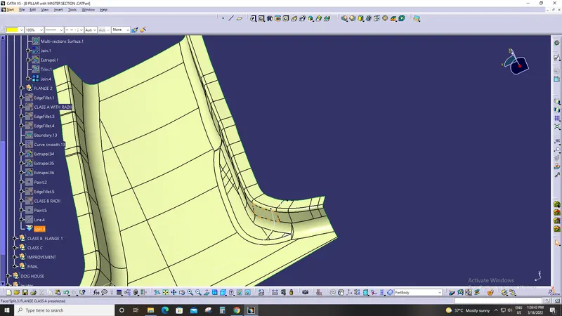
In the following image, the lines make “I” are the intersection of the flange and class-A surface which clearly are not in line with the master section as in it the lower line represent the same.
The lower line marked “E” is a parallel curve to the flange were we want the flange to be, so we measured the distance between the two and made an offset to that distance (this is the distance for offset (1)
B Surface creation
The next step is to design B surface for the input which is usually the surface where all engineering aspects and support
creations are done.
The B surface Creation is performed using surface operations in CATIA which is an offset from Class A with dimension
proportional to the thickness of the part In B Pillar Design the B surface is offset 2mm from the input which is the thickness of the part.
The B surface is an extrapolated surface compared to A surface and forms the bottom skin of the part .The Offset Surface leads to Surface Degenerations if
Rapid change in curvature or surface continuity
Low Radius of CLASS A
Conic or Styling Fillets
The Remedy is to untrim , extrapolate and trim or create surfaces using Multi Surface Option and Join
Corrected B Surfaces
In this way the Patches are coorected along the B Surfaces and the part is Extraploated with offset of 2mm from A Surface
C Surface Creation
The Next step is to from the C surface which is an intermediate surface between A and B and is used to give the closed surface
appearance to the design
The C Surface is swept using the profile as boundary line of Class A which is the Guide curve with a subtype along draft
direction.
The Direction of the sweep is the tooling direction formed earlier
The draft angle for the sweep operation is provided which is 3 Degree and surface is swept for length above the thickness of the
specified part
The C Surfaces must be drafted outwards from the A Side to avoid the parting Line along the A Surface
The C surface is refined using smooth Curve options to remove the complexity and patches along the swept surface
Finally the Class A and Class C surfaces are joined together and connexity of surfaces should be less than 0.003mm and the
surfaces are merged.C Surface merged with Class A
Closed Body Creation
The merged surface is then trimmed with B surface to form the closed surface.
The Closed surface is then validated to find the irregularities along the edges and imperfections along the edges were then
corrected using operation like extrapolate and surface trim
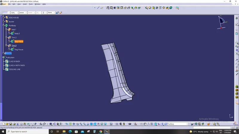
This Closed surface is the outer skin and finally the part is formed by Closed Surface in part design workbench
The final part is measured to validate the uniform thickness of the part especially along the filleted edges.
The Uniform Thickness ensures that the part Created doesnt form Sink Mark and Flow Lines along Class A
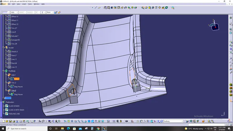
ATTACHMENT FEATURES
The attachment features are the fixation and location features that fixes the components.
The common attachment features used in
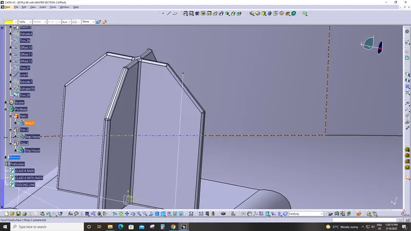
Doghouse with four Way Locator
Ribs
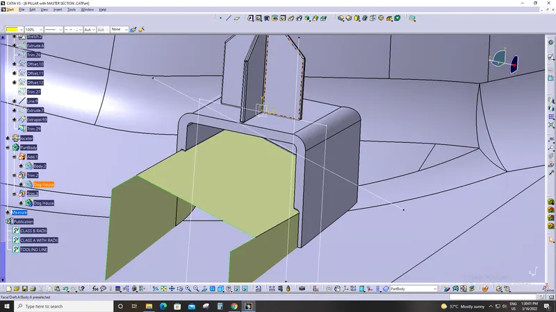
DOG HOUSE
Dog house is an engineering feature used in plastic trim design. Dog houses are used as supporting feature. Sometimes other engineering
features like snaps; locators etc. are mounded on them to increase their strength.
Dog houses are subjected to draft analysis to prevent breakage of thecomponent during ejection from mould cavity. Dog house and other
engineering components are built on B-surface
DESIGN RULES FOR DOG HOUSE:
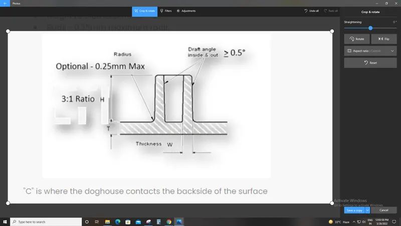
Minimum height: Less than 6mm causes steel condition.
3:1 ratio of steel width to height. But 2:1 is preferred.- Minimum width: 3:1 ratio of steel width to height. But 2:1 is preferred.
Draft: minimum 1.5deg.
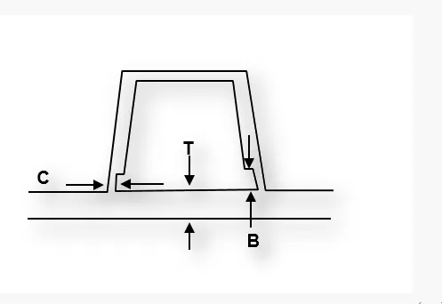
Sink saver: height (C) = 40% of nominal thickness.
Width (B) = 3.0mm-6.0mm.
Ribs
Ribs Provide Stifness To The Parts And Can Be To Impart Thougness Whthout Increasing The Part Thickenss And Are Locators And
Provide Allignment To The Mating Parts
The Design Rules For Two Way And Four Way Fixtures Are
-Rib Wall Thickness Should Be 0.4 Times Of Thickness Of The Part
-The Drafted Walls Of Rib Should Be Within 0.5 Degrees
-The Thickness Of The Rib, Fillet Radius, Draft And Rib Root Thickness Are Measured And Are Withing The Design Specifications
-In B Pillar The Ribs Are 50mm Apart On Both Sides
-Thus B Pillar Cover Is Surface Development Is Completed And Attachment Features Are Added.
-It Should Be Noted That The Fixation Of Bolt Locators Always Follow 3-2-1 Taylor Principle.
-Rotational Movement Along X,Y,Z Axis ( Clockwise And Anticlockwise)
-The Improvement In Given B Pillar Could Be An Addition Of Another Dog House At An Extreme End To Satisy The Taylor's
Principle And Thermal Stakes Are Provide That Arrests All Degrees Of Freedom And Completly Fits The B Pillar Part
Draft Analysis Procedure
-The Part Created Has To Be Changed To Material Mode In Display Frame
-Then By Enabling Compass Definition The Axis System Is Pan Along The Direction Of The Part And Aligned In Line With The Tooling
Direction
-Lock Direction Is Applied That Fixes The Compass And Then The Mode Dialog Box Is Formed By Snapping At Any Point On The Part
-The Color Codes Are Classified And Draft Angle Are Applied
-Then The Running Point Analysis Is Used To Hover Around The Part To Analyze The Permissible Draft Angles And The Analysis Is Saved
Draft Analysis Report
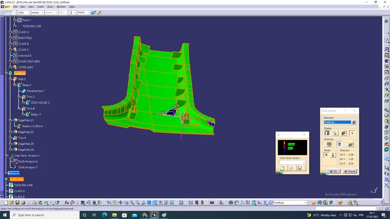
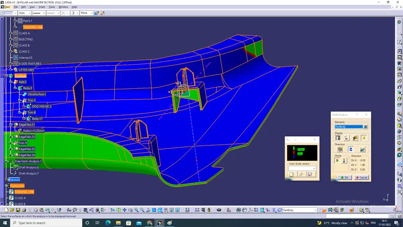
-The Draft Report For B Pillar Model Is Shown Below
-The Min. Draft For All A Side Surfaces Are 3 Degrees
-The Surfaces That Are Below 3 Degree Are Shown Below
-The B Side Surface Analysis Is Shown Below
Result
-The Green Color Is Drafted Walls Above 3 Degree
-The Blue Color Is Drafted Walls From 0-3 Degree
-The Red Surfaces Are Negative Degree
-The Analysis Shows The Drafted Walls Are Above The Par Of 3 Degree Which Is Permissible To Manufacture In The Injection Modeling
-The Running Point Analysis Hovered Along The Drafted Walls Show Parts Are Above 3 And Will Be Easily Cleared From Ejection.
Conclusion
Thus a Tooling Axis Is Created And a Open Aesthetic Class A Surface Is Developed Into a Closed Surface With All Plastic Design Rules
And a Final Part Body Is Created Out Of It In Catia Surface Work Bench. The Design Is Then Validated With Master Section And
Understood The Use Of Master Section Development In Product Design Through Development Of B Pillar Cover Used In The Car