Week 9 - Project - Master Section Development
DESIGN OF THE B-PILLAR THROUGH MASTER SECTION DEVELOPMENT
AIM:
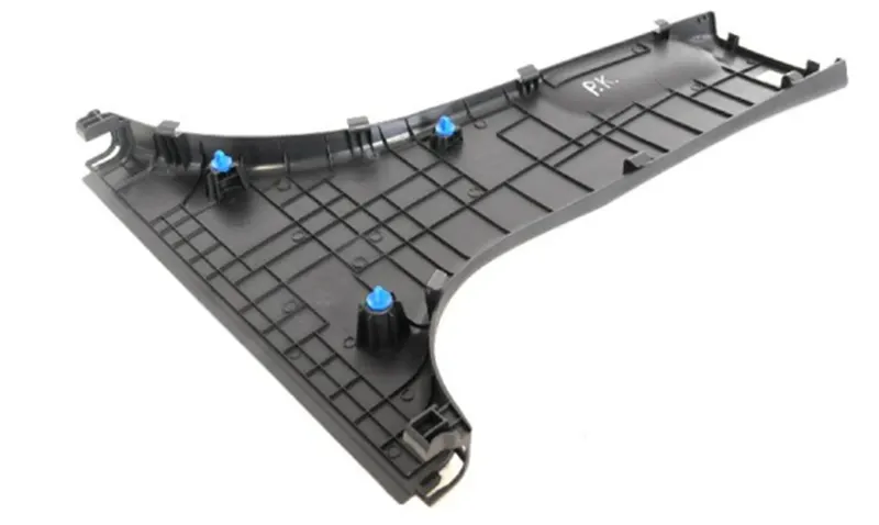
To design and develop B-Pillar from given Class ‘A’ surface and master section into a functional product design following the OEM design standards using CATIA V5 Surface workbench and Part Workbench following the injection moulding principles.
ABSTRACT:
This report describes the designing/approach of designing followed in the industries. In this model we had to create a close solid body from the aesthetic surface provided and later work on the engineering features considering every standard design rule followed in the OEMs on the B-side of the model. Pillars are the vertical or near-vertical supports of a car's window area or greenhouse,designated respectively as the A, B, C, or (in larger cars) D-pillar, moving from front to rear, in profile view.

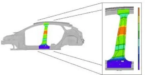
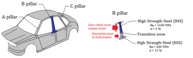
B Pillar is the central pillar of the car. It is the most complex component or structure of the vehicle body. This is because the front door attaches to the B pillar and the rear door hinges to the B pillar. The B Pillar is welded to the top panel of the car and the floor panel of the car. Hence B-Pillar provides structural support to the roof. The report explains the steps followed in creating the tooling axis followed by detailed methods in creating Class ‘B’ Surface, Class ‘C’ Surface, and to closed body. The overview of the approach followed is mentioned below:
- Check for any defects or irregularities in the class-A surface.
- Make a tooling axis.
- Run the draft analysis beforehand in case if there are any faces which do not have drafts,
those can be corrected by the class-A designer.
- Understand the master-section.
- Make the flange on both sides to make the aesthetic model complete.
- Make class-B and class-C surfaces.
- Make a surface model by trimming surface A, B, and C together.
- Close the model.
- Make a B-side feature.
- Run draft analysis on the final model and make a report.
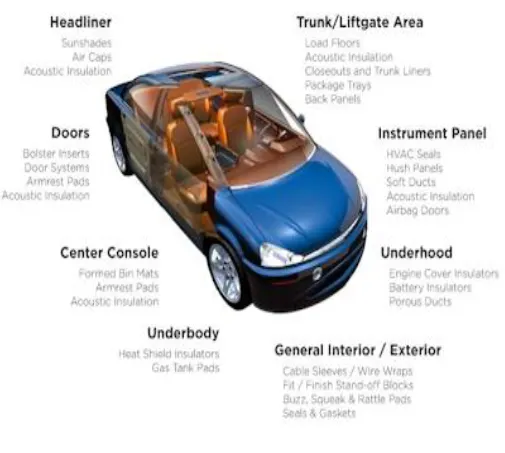
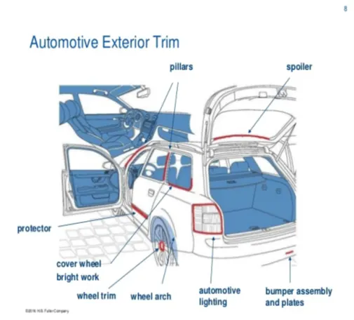
Automotive trims (interior and exterior): Trims are the plastic parts installed on the inside and outside of a car. The interior trims are usually used for giving the aesthetic look to the interior of the car. There are various types of trims used in automobiles Functionality and aesthetically pleasing trim applications are crucial factors for a perfect interior experience and successful vehicle sales. The selection, design, and processing of plastics solutions for interior trim components are very important for consumers when making their purchase decisions. Trim applications require a variety of essential plastic material properties:
- High-quality aesthetics and haptics
- Reliable stability and long-term durability
- Ability to withstand UV light and exposure to high temperatures
- For load-bearing trim parts: enhanced stiffness retention at elevated temperatures and high dimensional stability
- Tight fit if assembled with other interior components/materials Impact resistance and good ductile performance at low temperatures, especially with safe component (airbags, passenger restraint systems).
DESIGN APPROACH:
- Check for any defects or irregularities in class-A surface.
- Make a tooling axis.
- Run the draft analysis beforehand in case if there are any faces which does
not have drafts, those can be corrected by the class-A designer.
- Understand the master-section.
- Make the flange on both sides to make aesthetic model complete.
- Make class-B and class-C surface.
- Make a surface model by trimming surface A, B and C together.
- Close the model.
- Make B-side feature.
- Run draft analysis on the final model and make a report.
A surface:
A surface is the styling surface that is visible to the consumer and gives an aesthetic look for the model designed. Surfaces which is having curvature continuity is also called Class A Surface. Engineering features are not added to this surface.
B Surface:
Class B surfaces are the secondary surfaces that you can see sometimes includes all the engineering features such as dog house, locators, ribs, flanges, etc. This
surface is the direct offset of the Class A surface which gives thickness to the component.
C Surface:
This surface is the combination of the Class A and Class B surfaces also they are the backside surfaces that can have tool marks, flash, and other imperfections without hurting appearance, function, etc.
GIVEN:
1.A-surface
2.Master sections
3.Distance between ribs should be 50mm.
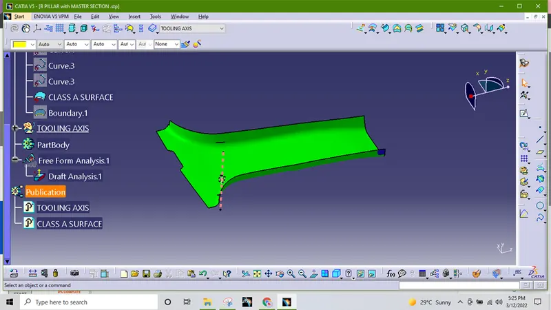
Tooling axis:
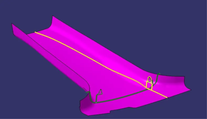
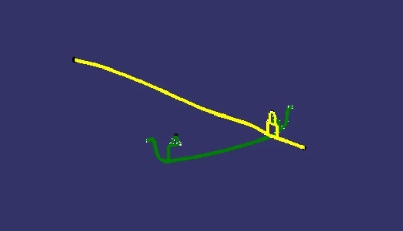
The given Class A input is analyzed to envision the part to manufacture and the Tooling axis or Tooling Direction is the direction that molds pull apart in injection molding. There are two mold pieces names core and cavity. Thus, tooling direction determines Mold separation and also becomes vital in developing the plastic product which is drafted to desired nominal angle for feasible clearance and ejection of the final part from the mold.
The Steps Followed in creating Tooling Axis:
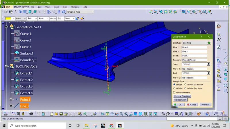
- A Reference Point is created along the Surface zero and a new Axis system is created.
- The X Direction and Y direction along the Class A were used to create the Tooling direction.
- Finally the Tooling axis is created by bisecting the two lines and it is published. Class A Surface as input using surface operation commands Class B is developed.
- The tooling Axis determines the direction of Class C boundary swept with draft direction.
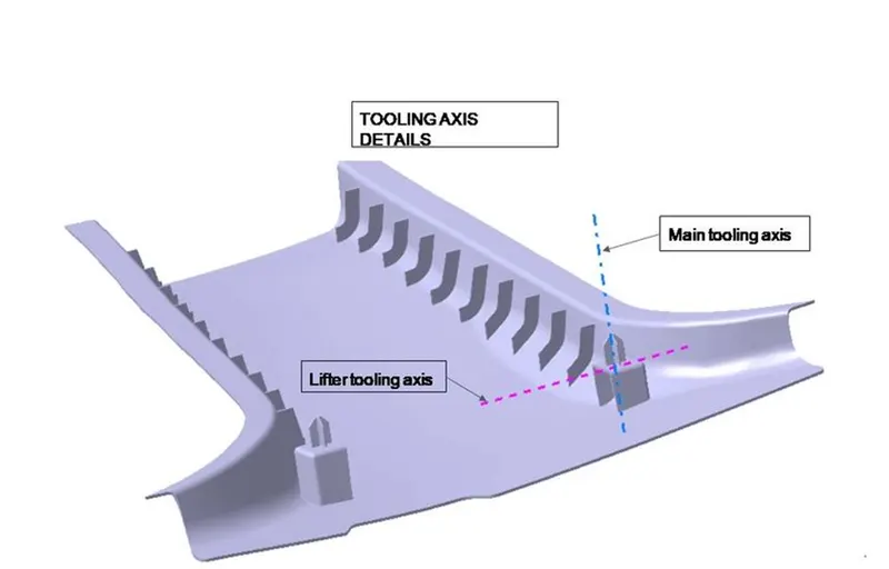
- When viewing from tooling direction normal all the parts that are drafted should be visible so, it gives a rough idea to determine product manufacturing in Injection molding. In B Pillar Model there are Two Tooling Directions one on the Main tooling and the other on Lifter Side that is used to eject the parts during injection molding.
Lifter Axis is used because the Attachment feature is bounded by close walls.
B-Surface creation:
According to the master section, the offset value for the B-surface is 2mm.
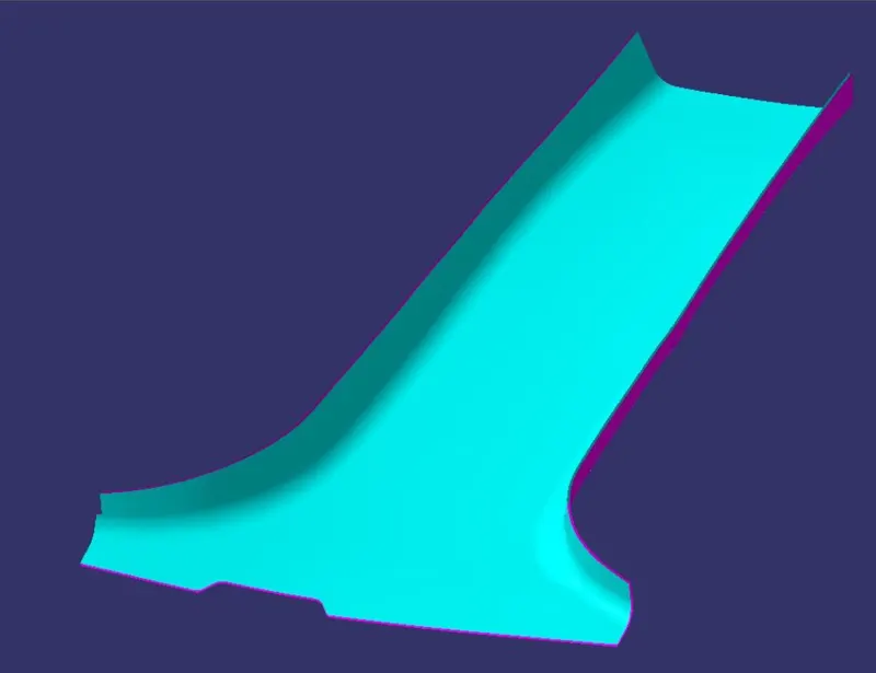
The creation of the flanges was the next procedure. For that purpose, master sections are provided. I created two flanges using the master section on the class B surface.
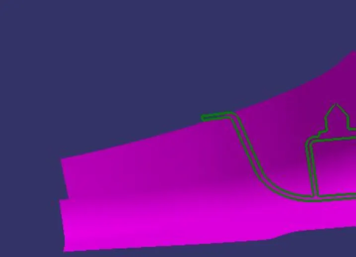
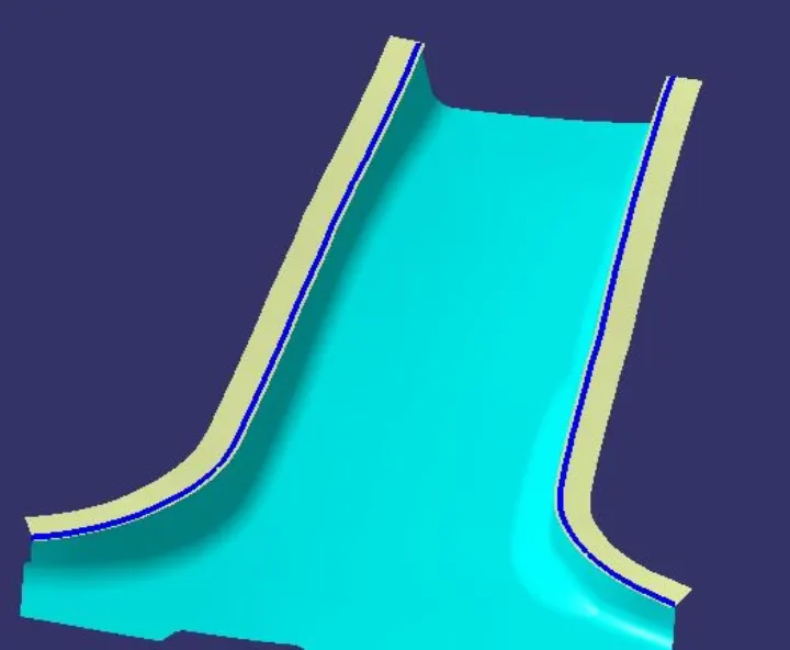
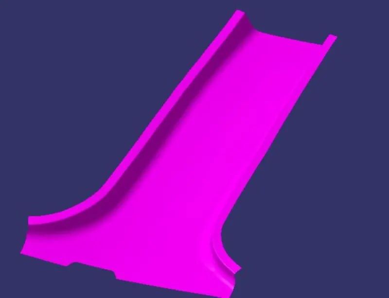
Now create offset of 2mm. The offset created a patch after working on the patch and trimming it with A surface gives Complete Class ’A’ Surface.
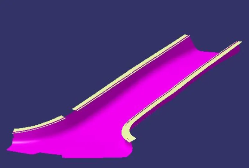
CLASS A SURFACE
C Surface Creation:
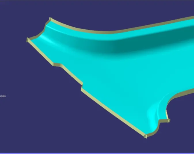
The Next step is to from the Class C surface with a nominal draft direction of 3 degrees with the tooling direction. so that flash occurs along the boundary of B surface. At some edges, we extrapolated so they intersect each other.
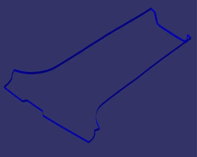
Once this is done, we have to trim all of them with each other to get the class-C surface. We have extrapolated class-B with flange too, so that it intersects with class-B and we get the required class-C surface after trimming.
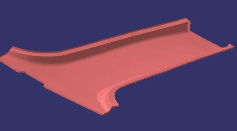
Combined class B and C surface
FINAL BODY CREATION:
Both B and C surfaces were joined together and trimmed with the A surface for final closed surface creation. The closed surface was inspected for openings using the ‘Boundary’ tool. There were no openings and the surface was perfect.
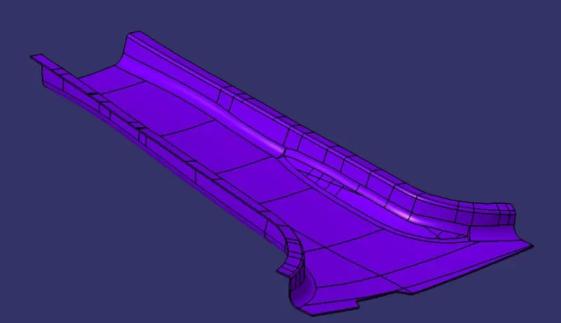
Draft Analysis for Plastic Component:
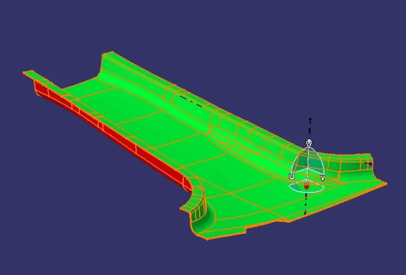
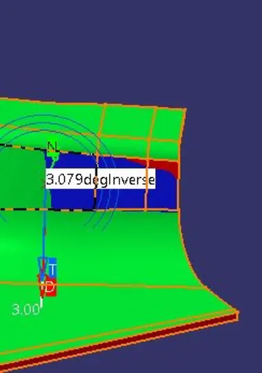
This patch needs to work on for draft angle purpose we should not make any changes. But, need to informed to Class ‘A’ surfacing team.
B SIDE FEATURE
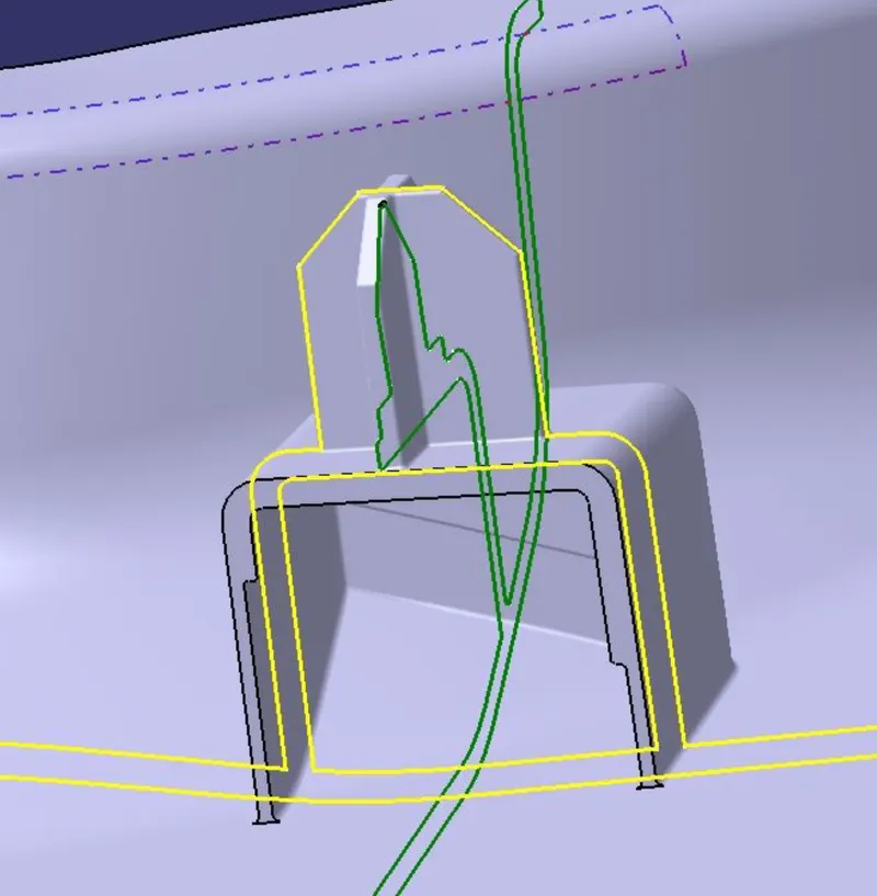
Once we get our solid model, we can start working on B-side features. We will get the required information from the master section. On observing the master section, we came to a conclusion that the features are dog house, 4-way locator pin and ribs.
The Attachment features are the Fixation and Location features that Fixes the
components The Common Attachment features used in B Pillar are:
- Doghouse with 4 Way Locator
- Ribs
The dimensions of the dog house and the four-way locator are taken from the
master section.
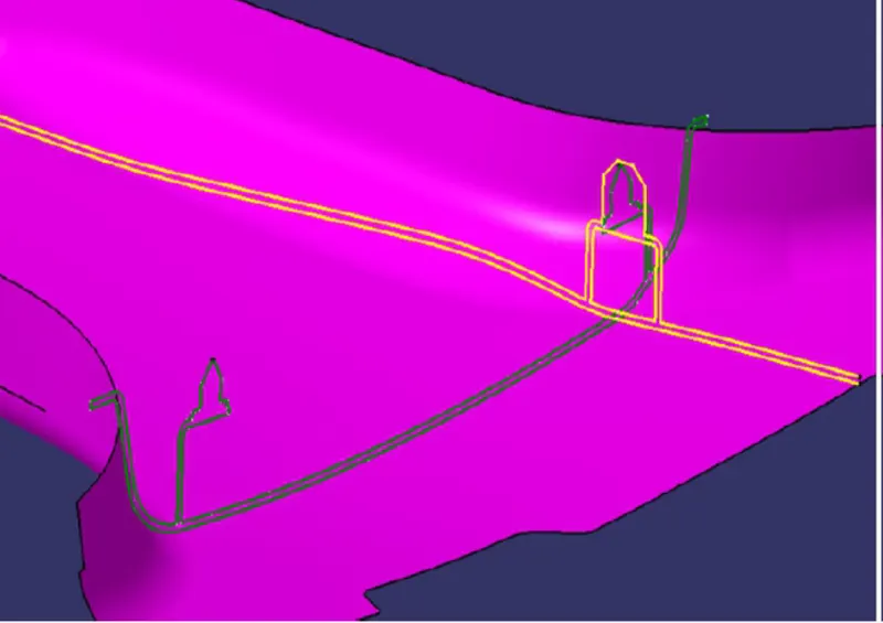
MASTER SECTION: These are the guidelines provided to a design engineer which describe how a component would/must look like once it is modeled into a solid component from the class-A surface. For example, in this model, we have received a master-section as an input which tells us about the thickness of the component and dimensions & type of the engineering features on the component.
DOG HOUSE &FOURWAY LOCATOR: Dog house is an engineering feature used in plastic trim design. The primary function of a dog house is to avoid sink marks on the class A surface which may occur due to features such as a thick screw boss or rib on the backside of Class A. So, the best possible solution is to increase the height and decrease the cross-sectional thickness of the ‘legs’ by using a dog house. We can also use them for solving the necessity of large length features such as a screw boss which may require a large length sometimes. We can use a dog house and make a screw boss above it in such situations. We can also use them for making
features that are perpendicular to the main tooling direction.
Ribs: Ribs provide a means to economical stiffness and strength in molded parts without
increasing overall wall thickness. They also facilitate:
1) Locating & arresting components of an assembly.
2) Providing alignment in mating parts.
3) Acting as stops or guides for mechanisms.
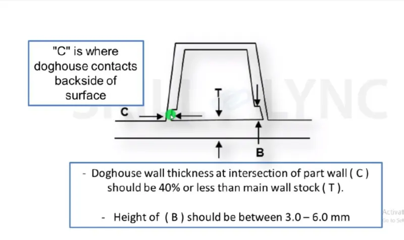
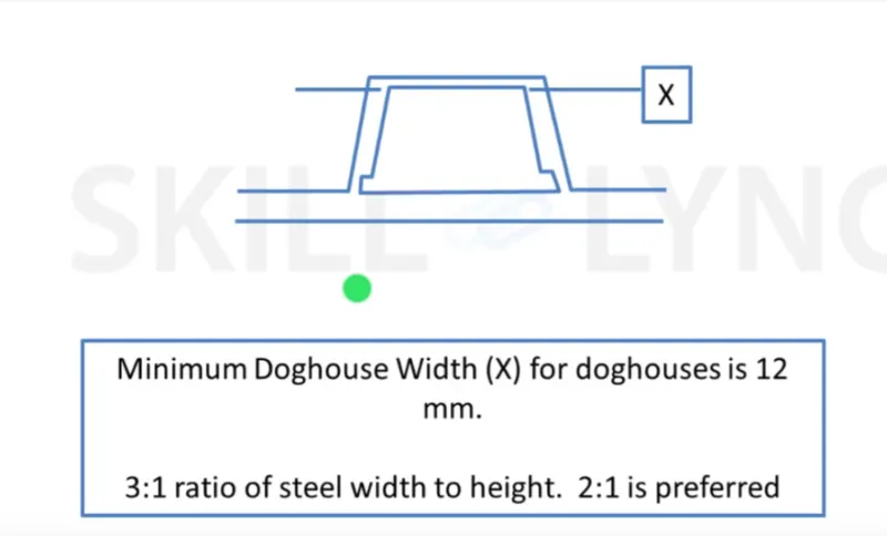
DESIGN RULES FOR DOG HOUSE:
- Minimum height: Less than 6mm causes steel condition.
- 3:1 ratio of steel width to height. But 2:1 is preferred.
- Minimum width: 3:1 ratio of steel width to height. But 2:1 is preferred.
- Draft: minimum 1.5deg.
- Sink saver: height (C) = 40% of nominal thickness. Width (B) = 3.0mm-6.0mm.
- Optimal radius:25mm
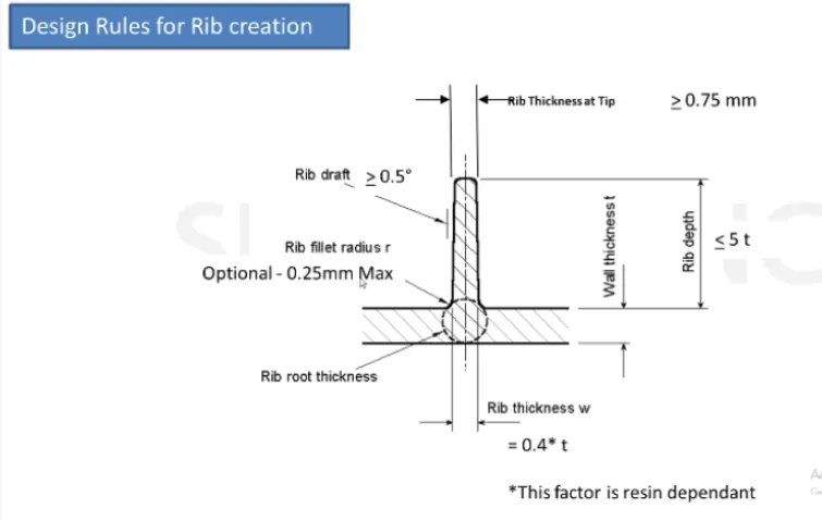
DESIGN RULES FOR RIBS:
- Draft: 0.5 deg per side (minimum), but this value should not be high enough that it will cause
failure for other considerations. For example, more draft will result in less thickness at the
top surface.
- Thickness of ribs: 40% of wall thickness or 0.4*t where t is the wall thickness.
- Height: ≤ 5 times the wall thickness i.e., 5*t.
- Spacing (for more than 1 rib): 3:1- steel height/width ratio (maximum). h/w =3or2(preferred)
where h is the height of the rib and ‘W’ is the space between two ribs.
- Minimum thickness at the tip: 0.75
- Radius: 0.25mm max.
- Ribs on the opposite side of the wall should be offset.
- Ribs should be connected to other structural features where possible.
- Rib root thickness should not be more than 30% of the wall thickness.
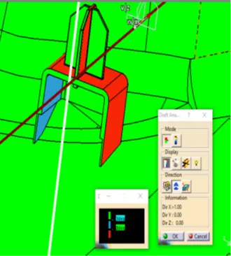
DOG HOUSE 4 WAY LOCATOR
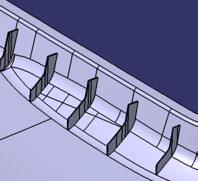
RIBS
The only detail we have about ribs is that they are 50mm apart, so we make the ribs according to the design rules which are 50mm apart. They ribs should not be greater in height than flange. And also, we will consider the height from the side wall according to the rules. Once that is done, we will use Boolean operations to join it to the main body.
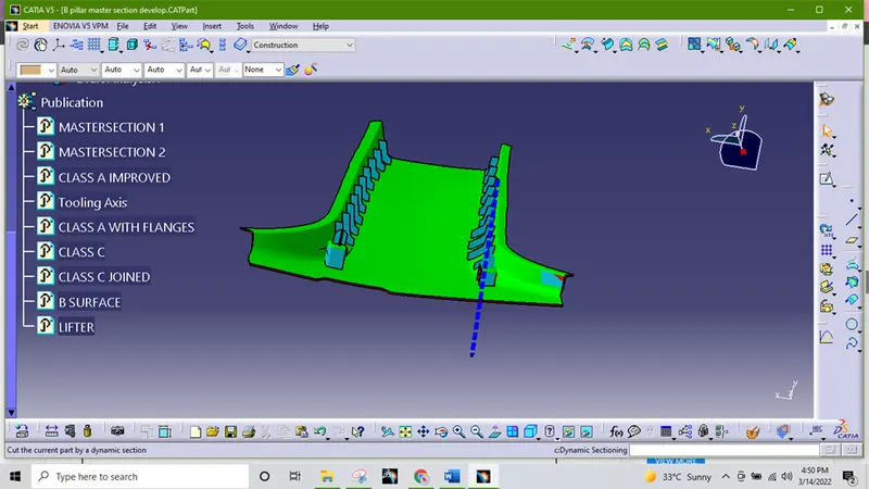
This analysis is with respect to lifter tooling axis, all the faces have 0.5deg draft.
B PILLAR DRAFT ANALYSIS REPORT
CLASS A SURFACE
Minimum draft angle should be greater than 3 degree the green portion following 3-degree draft
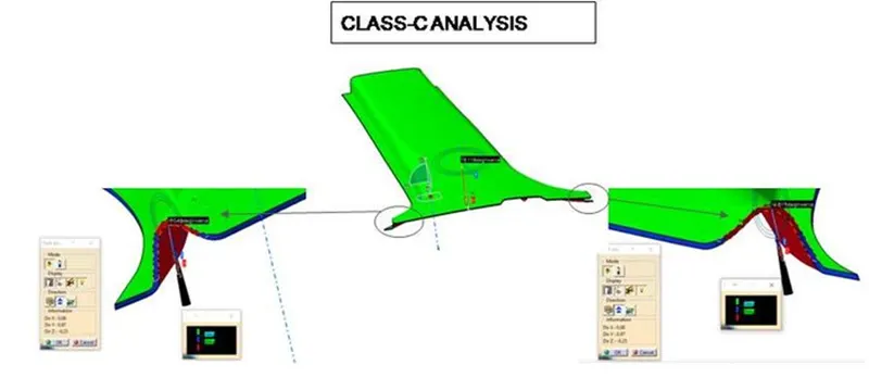
Above region show that not following draft angle 3 degree.
DOG HOUSE WITH 4 WAY LOCATOR ALONG LIFTER AXIS
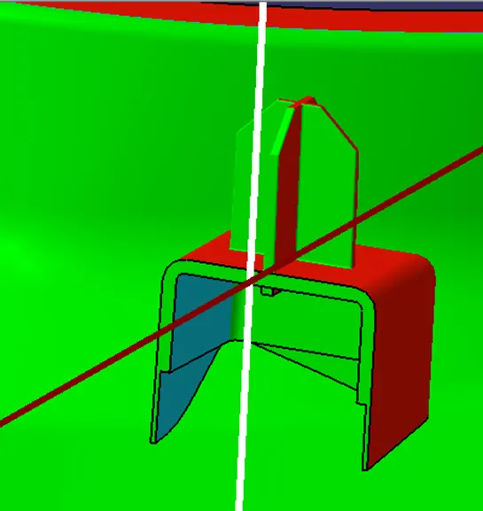
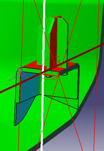
Cyan color region shows the draft angle .5 degree and green region 3degree.
Main tooling Axis Draft analysis
DESIGN VIEW
ISOMETRIC VIEW
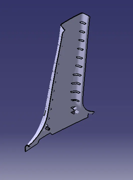
FRONT VIEW
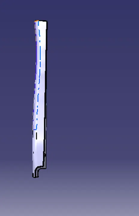
RIGHT SIDE VIEW
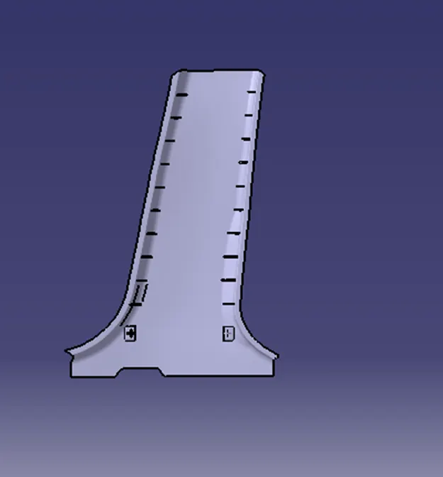
TOP VIEW
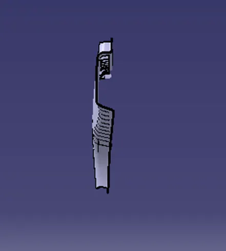
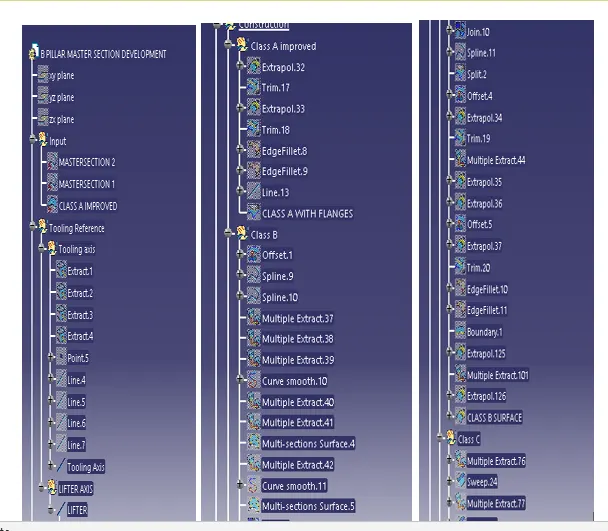
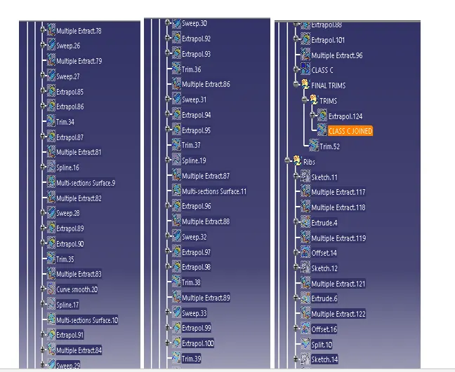
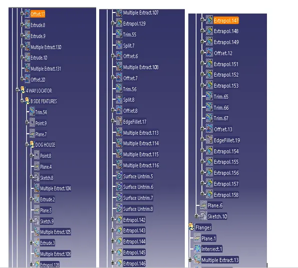
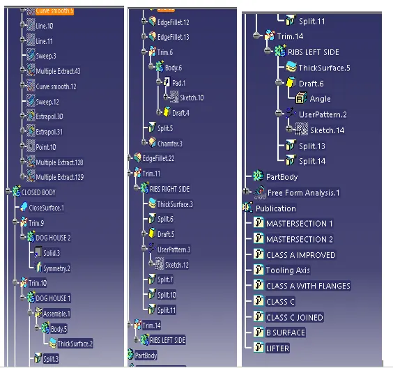
TREE
Conclusion:
- The B Pillar trim is created using a generative shape design workbench.
- The model is designed with the nominal draft angle of 3 degrees for the component and 0.5 degrees for the engineering features.
- The Closed body of the model is created using close body command in part design workbench.
- The engineering features in the model are designed following the design rules.