Week 9 - Project - Master Section Development
MASTERS SECTION DEVELOPMENT
WHAT IS MASTERS SECTION ?
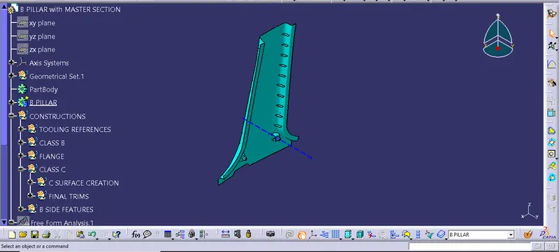
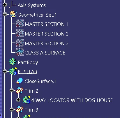
Masters section is nothing but the guidelines for the required design, that means the component is already designed, styled and concept. But in masters section the reverse engineering is applied the component is located using the guided lines, according to the design required and then it is manufactured. The below figure shows the Class A Surface with the masters section.
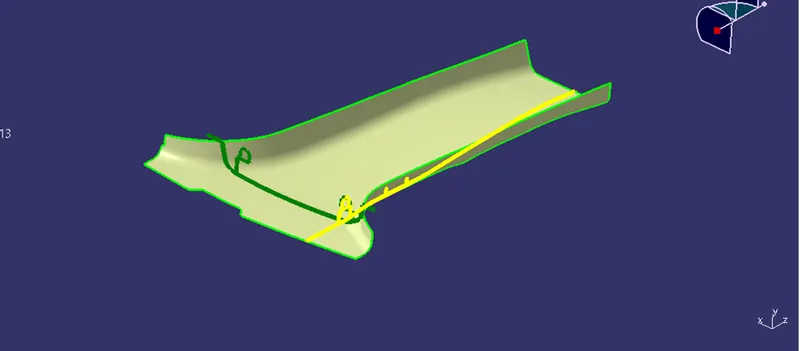
The above given surface is the Class A Surface of the B pillar with masters section.
Our task is to create the solid volume along with the B side engineering features out of this Class A Surface.
Designing of the B pillar :-
Initially we got the Class A Surface of the B pillar as an input along with the masters section. So now firstly the surface quality and continuity is checked using the boundary option or the join command as suitable. If the surface is continue without any break we can go for further procedure and if not so we have to update the surface locally using multiple extract and multi section solid commands.
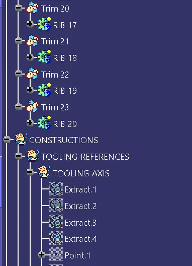
Now as the surface is continuous our next task is to create the tooling axis which acts as the license that the product can be manufactured. So as the masters section is given their intersection is provided as shown in the figure below.
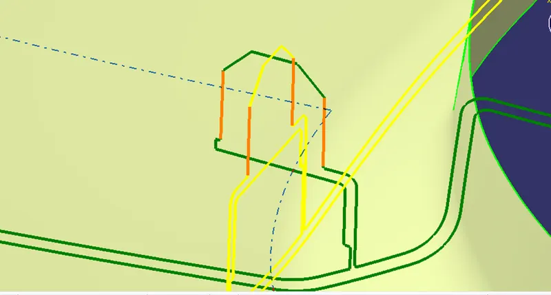
The above selected lines are extracted and the center point is created using the point command, then the lines are bisected diagonally. Finally two center lines are formed they are bisected with each other and a final lines generates that is our tooling axis as shown in the figure below.
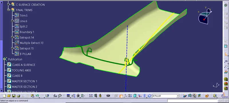
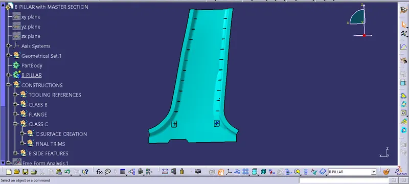
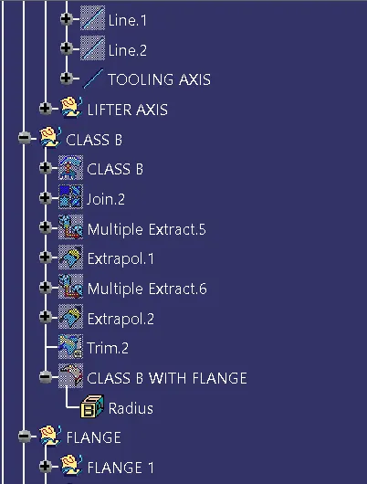
Now our next task is to create the Class B Surface out of Class A Surface. So there are two ways to create the Class B, either to extract the flat surfaces of Class A by ignoring the fillet and then offsetting it or to offset the whole Class A in the inward direction with the offset value of 2mm. Here the second method is used because it reduces the time and also the fillet value doesn’t impact that much on the A Surfaces i.e their value does not change as shown in the figure below.
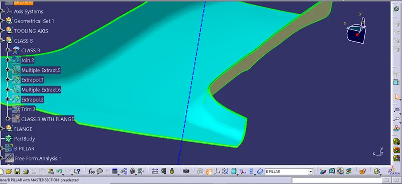
The blue color surface is the Class B Surface.
Now as shown in the masters section the pillar should have the flanges. Our next task is to design the flanges for Class B surface and Class A Surface as well as shown in the figure below.
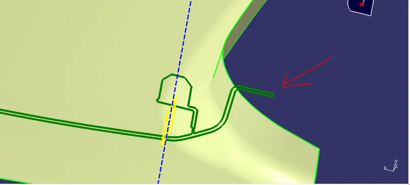
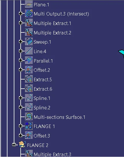
So now the new geometrical set is inserted named flange and then the three point plane is created by using the masters section and then the intersection of the masters section is created on to Class A as shown in the figure below.
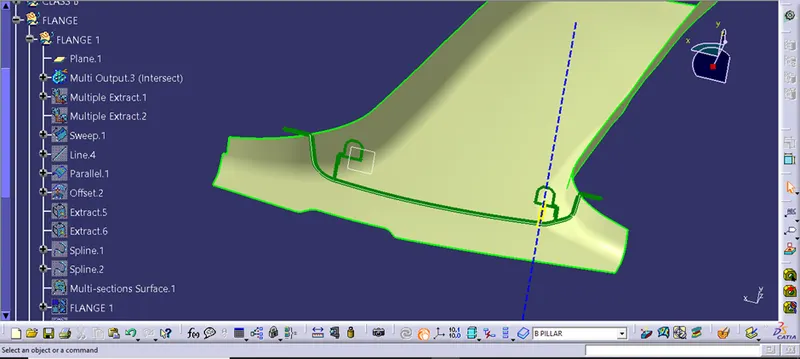
Now the side wall surface and the edge is extracted one by one and then it is sweep in the outward direction. And the line is drawn on to it in order to match the sweep with the master section flange line. Here the parallel curve is also created so to get the reference for the Class A Surface flange. Then as we offset the upper sweep 2mm in downward direction we get the sweep with the discontinuity of the surface as shown in the figure below.
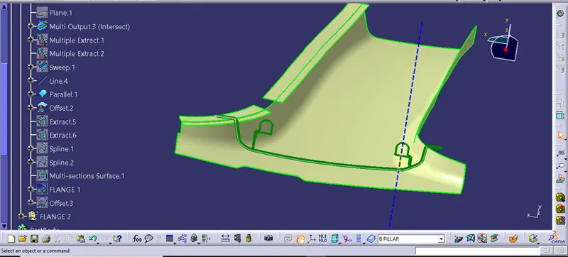
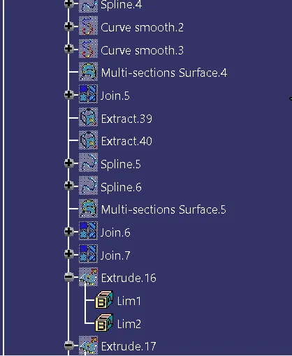
So to remove this discontinuity the surrounding surfaces are extracted and the spline is drawn to the both ends of the flange. And finally the multi-section surface command is used to close/join the two surfaces as shown in the figure below.
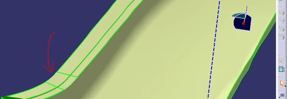
Finally the join is created of the sweep and then the offset is done as shown in the figure below.
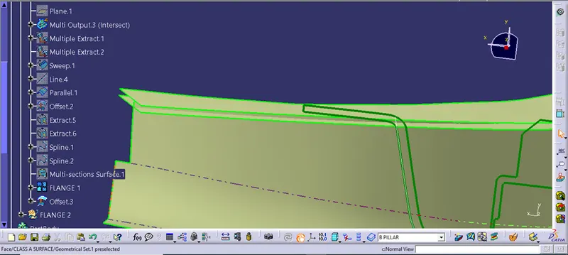
The upper flange for Class A Surface and the lower for the Class B surface as shown in the above figure.
This same procedure is followed for the creation of the second flange as shown in the figure below.
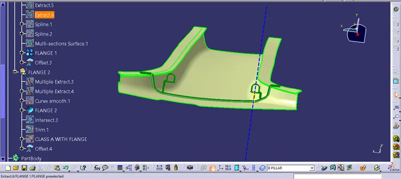
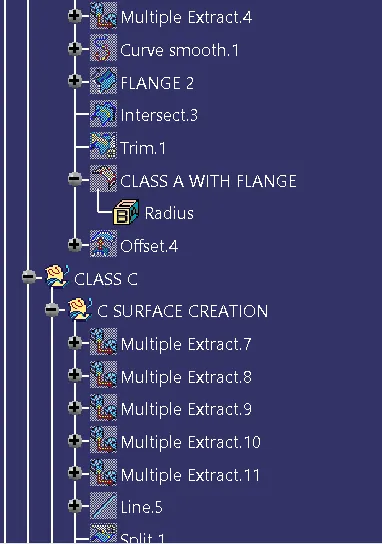
Now initially the Class A Surface is trimmed with flange and then the Class B surface is somewhat extrapolated upward and then it is also trimmed with the offset flanges as shown in the figure below.
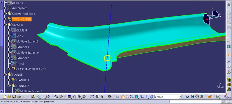
The upper one is the Class B Surface and the lower one is the Class A Surface with flanges.
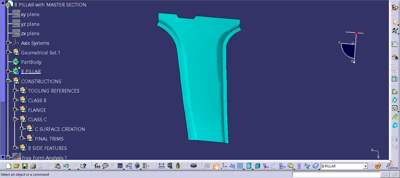
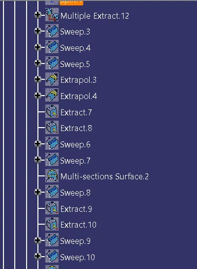
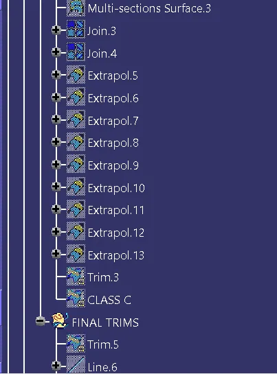
Now our next task is to create the Class C Surface in order to create the solid volume, so here all the edges of the Class A Surface are extracted and then they are sweep along the tooling direction/draft direction in the outward direction 3deg as shown in the below figure.
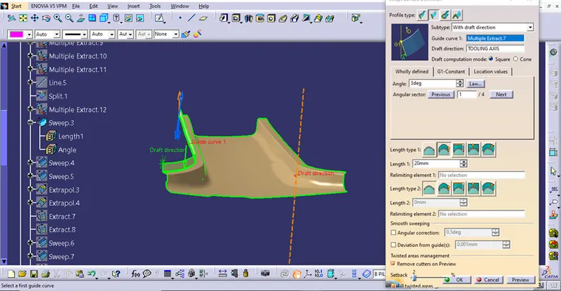
Each extract is sweep exactly as the figure and then the ends of the sweep are extrapolated in order to form an intersection for the further trim and hence our Class C Surface is ready as shown in the figure below.
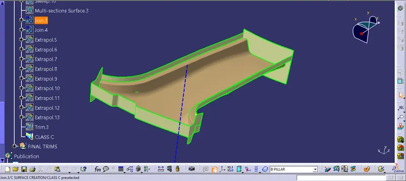
Now our task is to join the Class A and Class C Surface together as shown in the figure below.
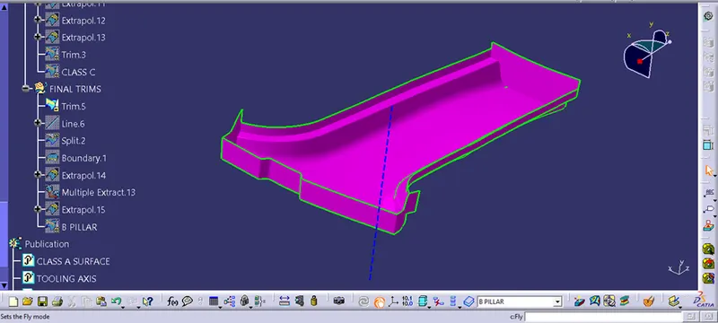
Now as the Class A and Class C are joined now the B surface is unhide and the intersection of Class C is checked with Class B Surface so here we get the unevev intersection i.e not all the edges of the Class B is intersecting the C Surface so here the boundary is created of Surface B and then it is extrapolated 3-4mm and then finally it is trimmed together with the Class A and C Surface as shown in the below figure.
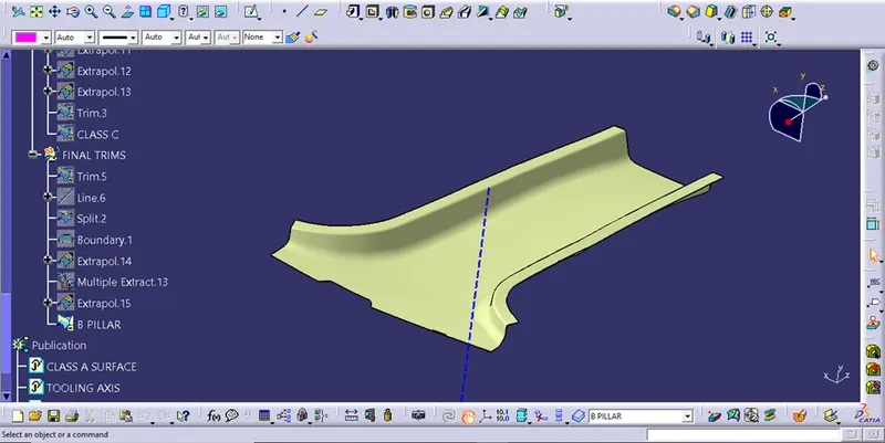
And then the new body is inserted and this B pillar is converted into the solid body using the close surface command as shown in the figure below.
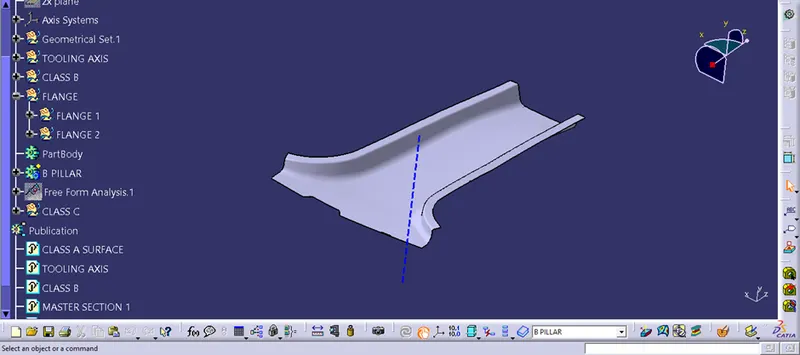
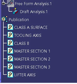
Now the most important step is that the draft analysis is to be done if the product can be manufactured or not.
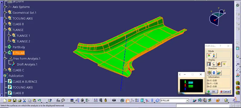
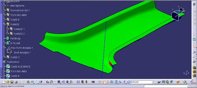
Hence our solid model is fully ready and is able to manufacture.
Now as our model is converted into the solid part using part workbench our next task is to create the B side features i.e is the masters section of the component.
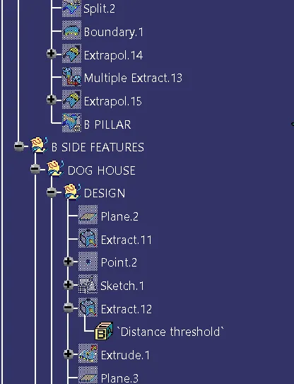
Initially the master section design is visually analyzed and tried to understand what actually the sketch wants to convey to us. As we analyze we get to know that to avoid sink marks on Class A Surface a dog house is to be created and then on to it the 4 way locator is to be designed.
Now the plane is created by referring the masters section and then all the inner outline of the master section is dimensioned and then it is extracted as shown in the figure below.
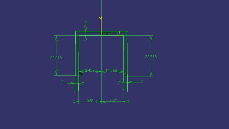
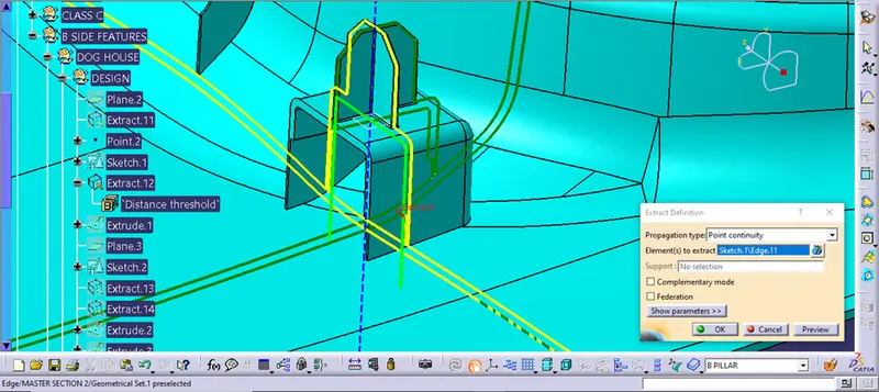
The above given sketch is the sketch of the master section 1.
The same way the master section 2 sketch is dimensioned and is extracted as shown in the figure below.
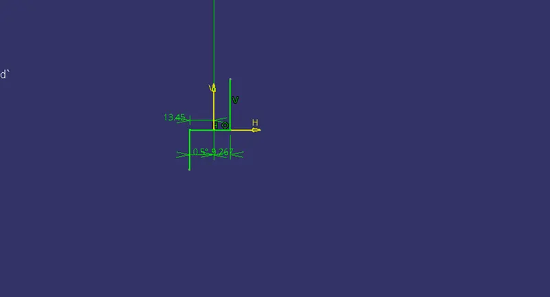
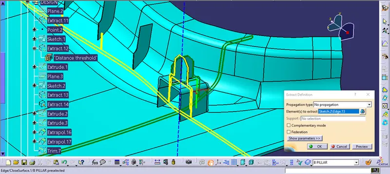
Now the extracted surfaces are extruded and are trimmed in order to form the dog house like structure as shown in the figure below.
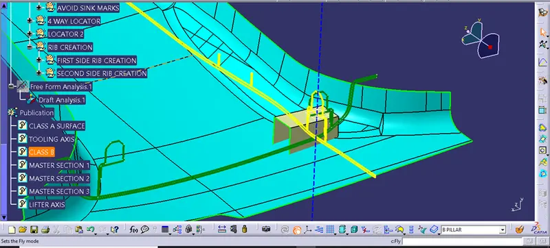
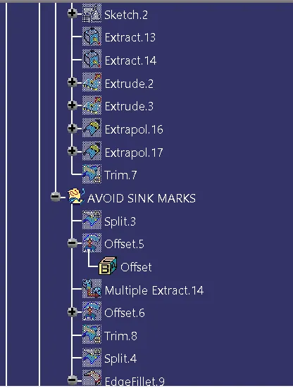
Now the split command is used to get the exact dimension of the dog house then the offset command is used to offset the dog house 1.2mm outward as we know that the base of the dog house should not exceed 40% of the component thickness. And the slot from the base to above should be from 3 to 4 mm so here the surface is extracted and is offset 3mm above and finally is trimmed with the early offset dog house as shown in the figure below.
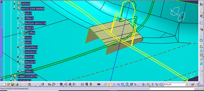
Then finally the body is inserted and then the thickness is given to the dog house of 2mm and the lower slot which we can see in the above figure is split with the main body as shown in the figure below.
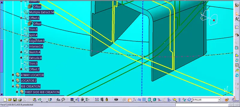
After the split the lifter axis is designed in order to clear the tooling of the dog house inner faces then the draft of 0.5mm is provided to the inner faces of the dog house as shown in the figure below.
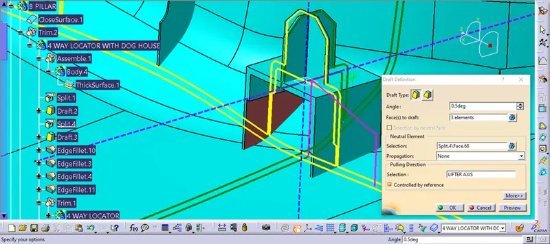
Now the design of the dog house is fully ready but the 4 way locator is yet to be designed.
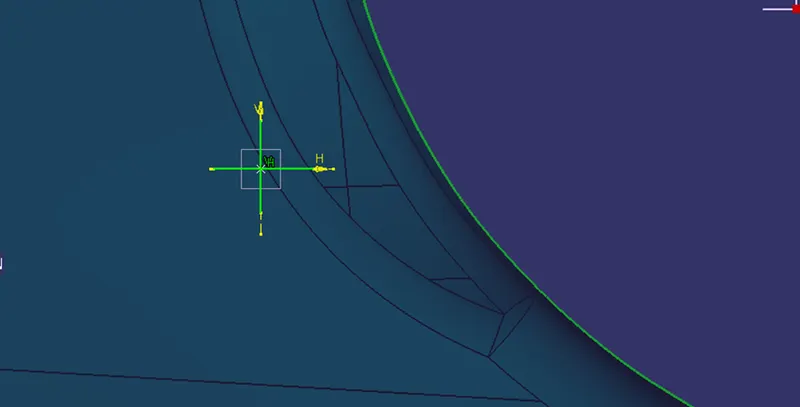
Now as we don’t have the proper dimension of the locators we will take the reference of the masters section. Here the top edges of the masters section are projected and then the sketch using the top edges is drawn as shown in the figure below.
Now a new body is inserted and the locators are pad in the above direction 20mm then the chamfer is provided to the edges of 5mm with 45 degree and finally the draft is given to the locator of 0.5mm as shown in the figure below.
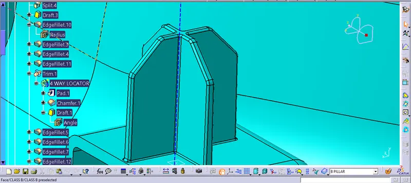
Now the work is defined in the main body work bench and the locator is trimmed with the main body in order to add locator and dog house to the main body as shown in the figure below.
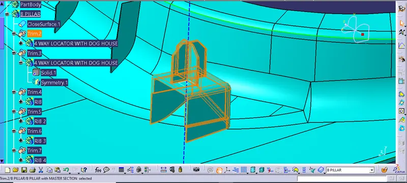
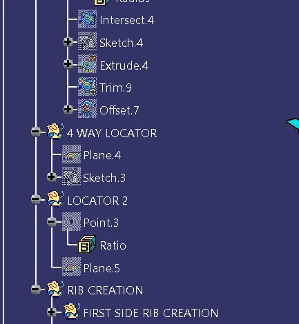
Now what we have to do is the same dog house with the locator is to be designed on to the next side/ opposite side so here the part as the whole is copied and is paste special as a result with link. Now the new point is created as a between point between the two locators point as shown in the figure below.
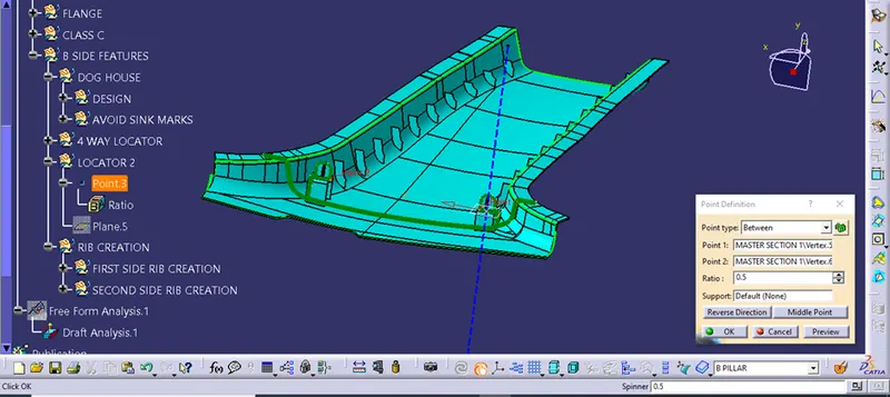
Then the plane is created on to the point and then the result link part is symmetry to the other side as shown in the figure below.
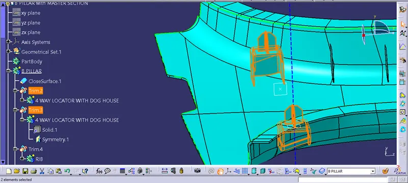
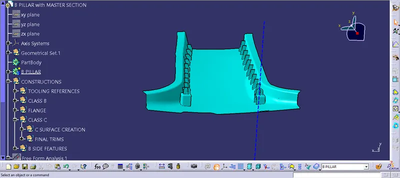
Now here comes the last feature of the B side that are the ribs.
To create the ribs there is nothing given as the reference but the distance between the two ribs should be 50mm.
So now here initially the sketch is created for the first side part of the ribs as shown in the figure below.
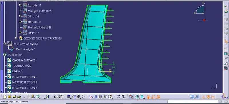
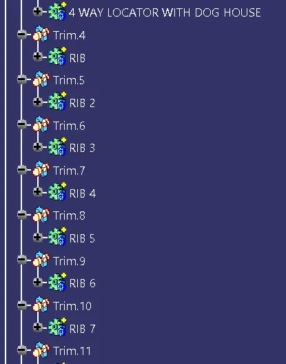
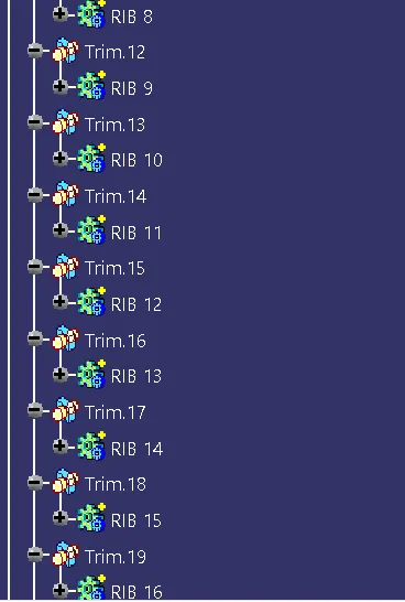
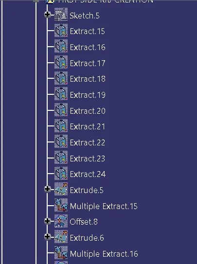
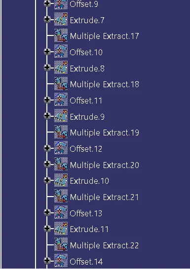
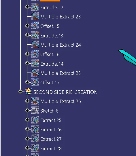
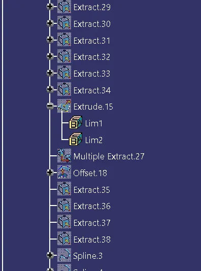
So as the sketch is ready all the lines are extracted one by one and then the sketch is extruded. After that as we know that the height of the rib should be 5 times the thickness of the component so here the base surface is extracted 10mm inward and then the ribs are converted into the solid body then the split command is used to split the extra surface which also gives the height to the ribs and finally the main body is defined and this rib is union trimmed with the main body as shown in the figure below.
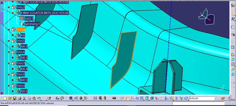
The same way all the ribs are designed. The designed ribs are shown in the figure below.
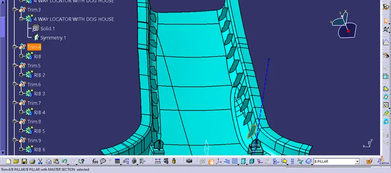
Hence our whole part is designed.
DRAFT ANALYSIS REPORT OF THE COMPONENT :-
Draft analysis of the Class A Surface :-
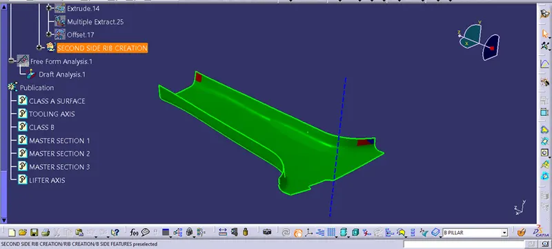
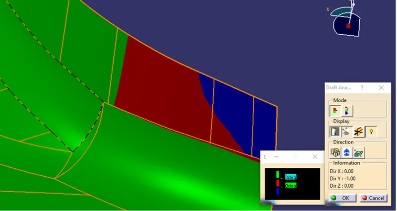
In the Class A Surface we get the minimum angle here is 1.95 degree but in the blue color surface the angle is in the negative. So here in this case we need to inform the head of styling department as they have the defect in Class A Surface.
Draft analysis of the Class B and C Surface :-
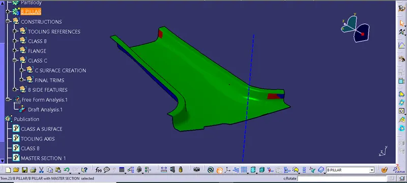
The above given analysis is of Class B and C surface.
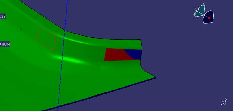
If we observe closely we get to know that the Class B surface have the minimum showing value in negative here the value differs from 1.99deg to -1.26deg as shown in the figure below.
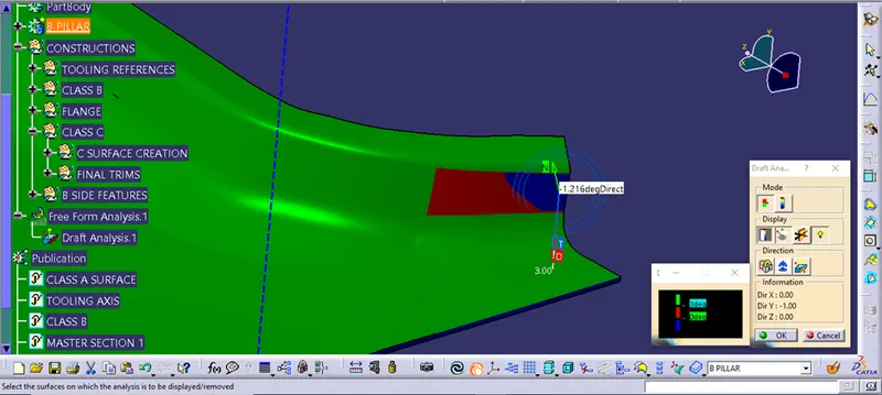
Now the analysis of the C Surface :-
C Surface is something that joins both Class A and B Surface and also shows the direction of the draft. Here the direction of the draft is shown in the figure below.
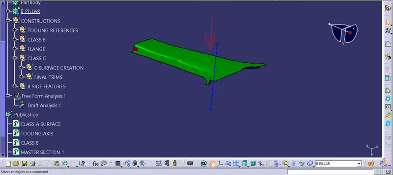
The arrow showing the draft direction.
Now as we observe the Class C Surface closely we get to know that the Surface is clearing the draft analysis as shown in the figure below.
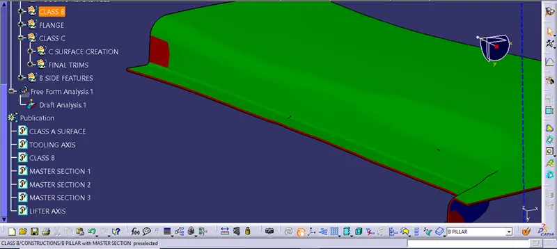
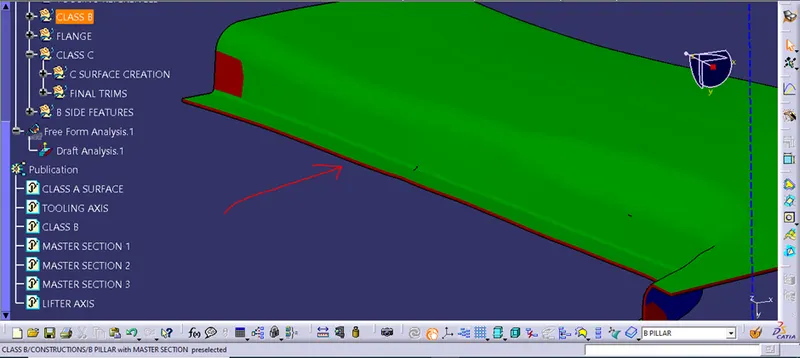
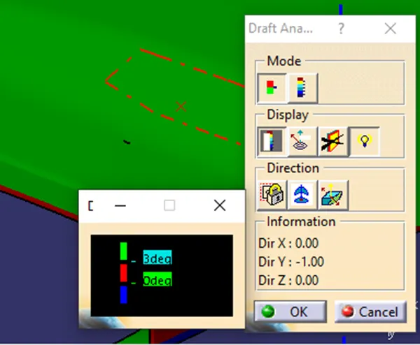
The arrows shows the Class C Surface that is clearing the draft.
Draft analysis of the Dog House:-
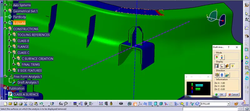
As we can see that the dog house is clearing the draft along the lifter axis.
Draft analysis of the B Side Engineering Features:-
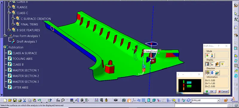
Now as we can see that the B Side features are also clearing the draft along the tooling axis. The engineering features have the minimum draft of 0.5 degree. As shown in the figure above.
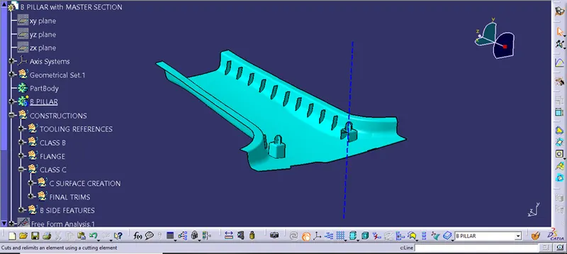
Hence our full component is designed along with the draft analysis and our component can be manufactured.
IMAGES:-